6 COMPONENT VIDEO INPUT 1-3, COMPONENT VIDEO MONITOR
OUT: Connect the Component Video Input 1-3 inputs to Component
Video outputs from compatible source components, typically a DVD player,
BD player and terrestrial or satellite HDTV tuner. Connect Component
Video OUT to the Component Video input of a compatible video monitor/
TV. Be sure to observe consistency in connecting the Y/Pb/Pr jacks to the
corresponding sources/inputs. The routing of the component video inputs
is fully congurable via the Source Setup item of the Setup Menu OSD.
The T 737’s component video inputs and outputs are fully wideband
and compatible with allowable HDTV formats.
The T 737 is optimized for Component Video Output. Composite
video and S-video sources may be viewed in their native format or via
Component Video Monitor OUT.
VIDEO INPUT
VIDEO OUTPUT
Component Video
Monitor OUT
S-Video Monitor
OUT
Video
(Composite)
Monitor OUT
Video (Composite) input Yes
(480i/576i only) Yes Yes
S-Video input Yes
(480i/576i only) Yes Yes
Component Video input Yes Yes
(480i/576i only)
Yes
(480i/576i only)
7 7.1 CH INPUT: Connect to the corresponding analog audio output
ports of multichannel source components such as a DVD-Audio or
multichannel-SACD player or external multichannel decoder (disc copy
protected formats only allow analog signal transfer). Typically, these
sources will produce 5.1-channel output, in which case the Surround
Back jacks are left unconnected. The signals present at these jacks
may be heard by selecting Multi (7.1 Channel Input is defaulted to this
Source setting).
There is no bass-management or other processing (other than volume
control) available to this 7.1 Channel Input. While the multi-channel
audio outputs of a DVD-Video player can be connected to these jacks,
using the T 737’s own Dolby Digital and DTS decoding and digital-
analog converters via a digital connection will usually produce superior
results.
8 SUBW PRE-OUT: Unlike full range channels, there is no power amplier
built-into the T 737 for a subwoofer. Connect the SUBW PRE OUT to
powered (“active”) subwoofers or to power amplier channels driving a
passive system.
9 FM, AM ANTENNA INPUT: Connect the supplied lead-type FM
antenna to the FM antenna input. Extend the lead. Experiment freely
with your antenna placement and orientation until you get the clearest
sound and lowest background noise. Fix the antenna in the desired
position by using thumb tacks, push pins or any suitable means.
The AM loop antenna supplied with the T 737 (or a suitable
replacement) is required for AM reception. Open the clip terminal
lever; insert the wire making sure to match the color-coded (white
and black) ends of the wire to that of the terminal and close the
lever ensuring that the lever locks the wire in place. Testing dierent
positions for the antenna may improve reception; vertical orientation
will usually produce the best results. Antenna proximity to large metal
objects (appliances, radiators) may impair reception, as will attempts to
lengthen the wire to the loop.
10 XM MODULE INPUT (120V version only): Connect XM radio cable
to this socket. Follow the instructions that came with your XM radio.
With XM radio, there are more than 100 channels of music, news, sports,
comedy, talk and entertainment. You will nd that the coverage is
continent wide. The music quality is digital with many commercial-free
music channels.
NOTE
The external XM radio is not supplied with your T 737.
11 UPLOAD MCU, RESET: The MCU, HDMI and RESET tact switches are
used for software program updates (if any) in combination with the
RS232. Your custom installer or dealer can assist you in the proper
upgrade and setup of your T 737.
12 IR IN/IR OUT 1, 2: These mini-jacks accept and output remote-
controlled codes in electrical format, using industry-standard protocols,
for use with “IR-repeater” and multi-room systems and related
technologies.
IR IN: This input is connected to the output of an IR (infrared) repeater
(Xantech or similar) or the IR output of another component to allow
control of the T 737 from a remote location.
IR OUT 1, IR OUT 2: Both IR OUT 1 and IR OUT 2 have dual-features –
they can act as an infrared command repeater or as stand alone IR OUT.
Connect the T 737’s IR IN to the IR OUT of ancillary equipment. Connect
also the T 737’s IR OUT 1 (or IR OUT 2) to another equipment with IR IN
feature. With this setup, the T 737 acts as an “IR-repeater” allowing the
equipment connected to the T 737’ s IR IN control or command of the
other equipment linked to the T 737’s IR OUT 1 (or IR OUT 2).
As a stand alone IR OUT, connect IR OUT 1 (or IR OUT 2) to the IR IN of an
ancillary equipment. Direct the ancillary equipment’s own remote control
to the T 737’s infrared receiver to command or control the linked unit.
13 +12V TRIGGER OUT: The +12V TRIGGER OUT is used for controlling
external equipment that is equipped with a +12V trigger input. Connect
this +12V TRIGGER OUT to the other equipment’s corresponding
+12V DC input jack using a mono cable with 3.5mm male plug. The
availability of 12V at this trigger output depends upon the setting of
“Trigger Out” in the TRIGGER SETUP OSD menu. See discussion about
“TRIGGER SETUP” at the “SETUP MENU” literature for guidelines on how
to congure “Trigger Out”.
14 MP DOCK: The T 737 is equipped with a data port in the rear panel
where an optional NAD IPD (NAD Dock for iPod) 1, NAD IPD 2 and later
variants can be plugged in. Connect the “MP DOCK (DATA PORT)” jack of
the T 737 to the corresponding “DATA PORT” socket of the optional NAD
IPD model.
NOTE
The external “NAD IPD (NAD Dock for iPod)” model is not supplied with
your T 737.
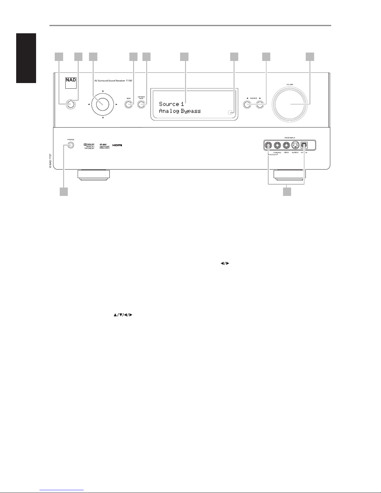
IDENTIFICATION OF CONTROLS
REAR PANEL
9
ENGLISHFRANÇAISESPAÑOLITALIANODEUTSCHNEDERLANDSSVENSKAРУССКИЙ