Nagano Keiki GC62 Series User manual

1 TY-GC62-010A Rev.2
GC62
Digital Differential Pressure Gauge
User Manual
7.1

2 TY-GC62-010A Rev.2
For Proper and Safe Use
Thank you for purchasing the GC62 digital differential pressure gauge. To use this product
safely and properly, read this user manual carefully. This pressure gauge can be used for
various applications including air conditioning related equipment. Incorrect use of it causes
failures, which may result in damage including faults or accidents.
Keep this manual safely after reading it so that you can always reference it.
■
Definition of Safety Terms
Safety precautions in this manual are categorized based on the following definition:
Indicates the risk that users may suffer from damage
including death or serious injury, and extremely high
urgency at the time of occurrence of risk.
Indicates the risk that users may suffer from damage
including death or serious injury.
Indicates the risk that users may suffer from minor injury
and the risk that only property damage may be caused.
■
Description of Graphic Symbols
Graphic
symbols
Meaning
●Generally prohibited activities
Indicates prohibited activities in handling the product.
●General instructions
Indicates activities based on instructions that users are forced to
conduct.
●Other information
Indicates precautions, special operating methods, and other
important information.
DANGER
WARNING
CAUTION

3 TY-GC62-010A Rev.2
■
Precautions for Handling Product
WARNING
●Do not give excessive load, vibration, and shock.
Damage to the product and release of a measured object may
be caused, which results in injury or damage to the
surrounding environment.
●Do not apply pressure over the maximum allowable pressure.
Damage to pressure elements may be caused, which results in
injury or damage to the surrounding environment.
●Do not use this product for measured objects other than our
specification such as dry air/N2.
Damage to pressure elements and release of a measured object
may be caused, which results in injury or damage to the
surrounding environment.
●This product does not have an explosion-proof structure.
Do not use the product in dangerous places with combustible
gas or liquid which may cause ignition or explosion.
●Do not use non-designated batteries and power supply.
Use of them causes failures, fires, or electric shocks.
●Make sure that dust or misty fluid does not enter the pressure
element which may cause inaccurate measurements or
product failure.
●If failures or malfunctions of this product may threaten human
life directly or cause harm to human bodies, do not use the
product.
●Do not modify this product.
Disassembly or modification of the product, or modification to
add new functions may cause harm to human bodies.
●Use the product within the operating temperature range.
Otherwise, the product fails or is damaged, which causes
injury or damage to the surrounding environment.
●Conduct wiring correctly according to the wiring nameplate or
the wiring procedure described in the user manual. Incorrect
wiring may cause failures or fires.

4 TY-GC62-010A Rev.2
CAUTION
●Install the product according to the installation procedure
described in the user manual.
●Operate switches accurately according to the user manual.
Incorrect operation of them may cause malfunctions.
●Contact us for repair.
Disassembly or modification of the product on your own may
cause failures.

5 TY-GC62-010A Rev.2
Table of Contents
For Proper and Safe Use..........................................................2
■
Definition of Safety Terms ...............................................................................2
■
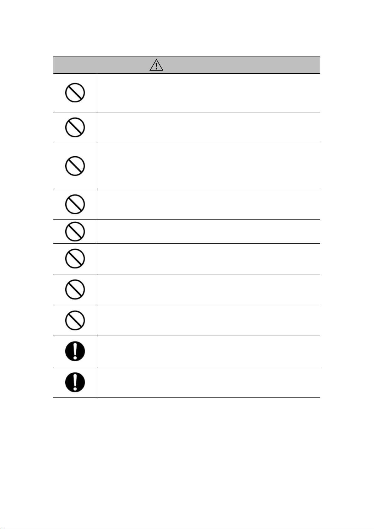
Description of Graphic Symbols.....................................................................2
■
Precautions for Handling Product..................................................................3
1. Preface ...................................................................................6
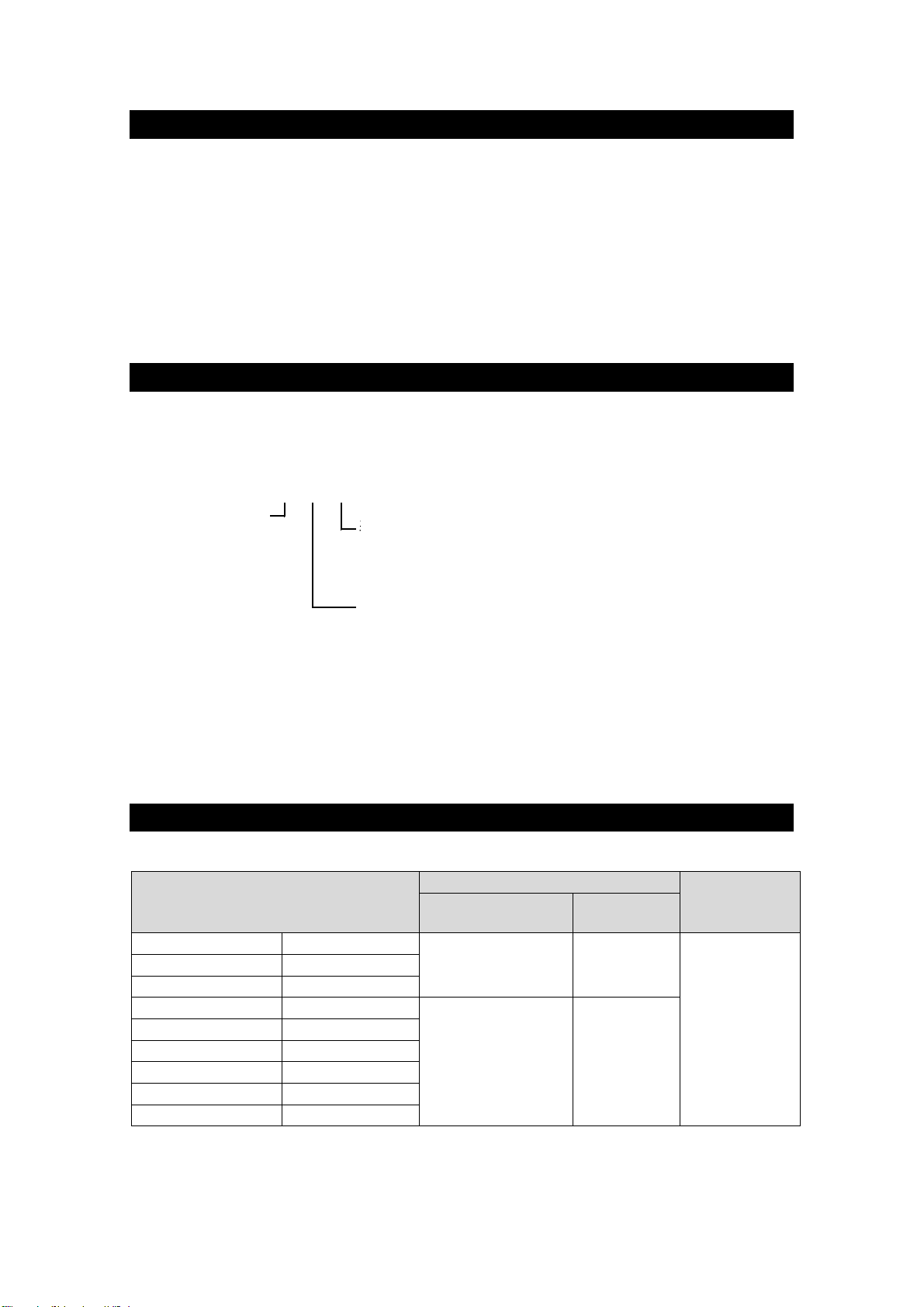
2. Model Number Structure......................................................6
3. Specifications........................................................................6
■
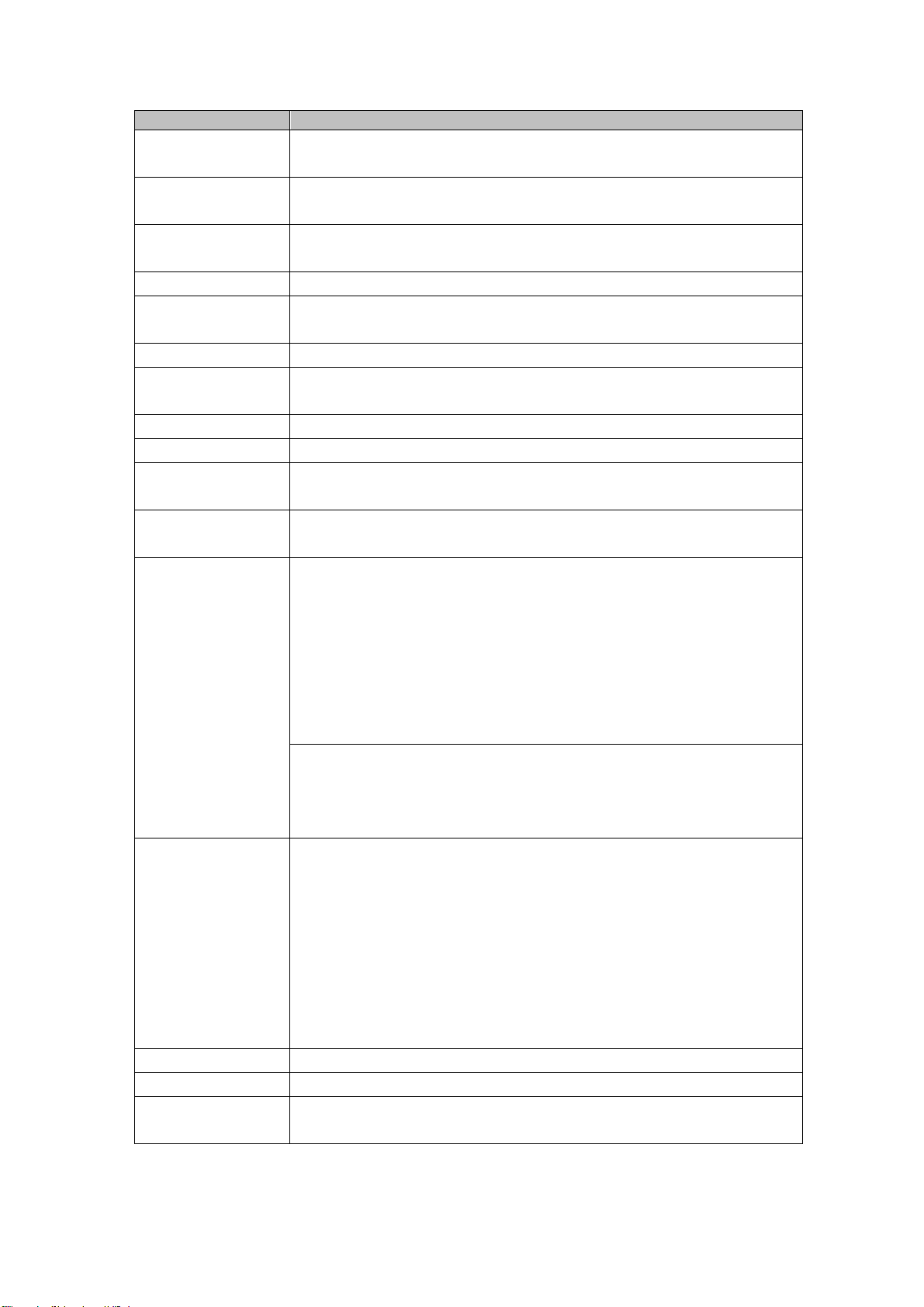
3.1 Product Specifications...............................................................................6
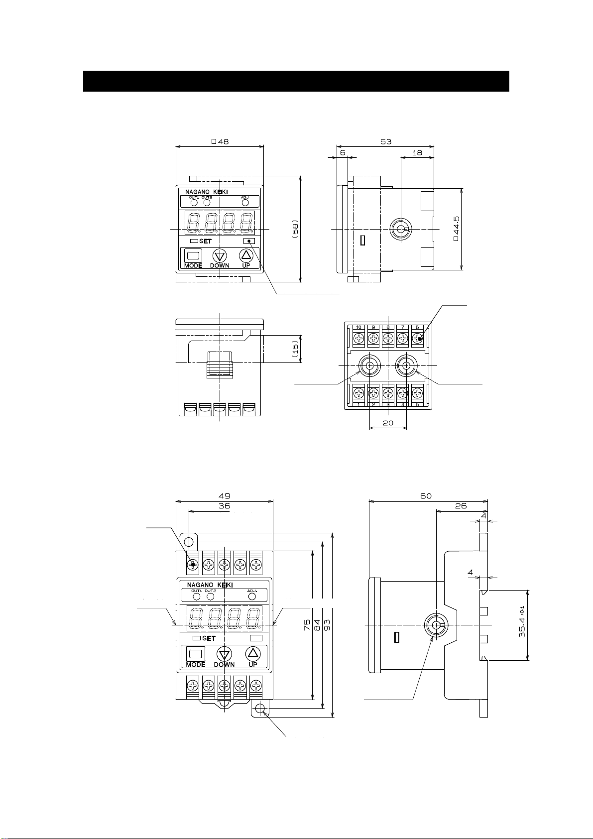
4. Dimensions............................................................................9
■
4.1 Outline Drawing of Pressure Gauge......................................................... 9
■
4.2 Wall Mount (DIN railing is attachable)...................................................... 9
5. Installation and removal.....................................................10
■
5.1 Piping.........................................................................................................10
6. Wiring and Connection.......................................................11
■
6.1 Wiring......................................................................................................... 11
■
6.2 Internal Format..........................................................................................12
■
6.3 Contact Protection....................................................................................12
7. Usage and Settings.............................................................13
■
7.1 How to Switch to Each Mode...................................................................13
■
7.2 Function Setting Mode.............................................................................15
■
7.3 Comparator Setting Mode........................................................................18
■
7.4 Comparator Operation.............................................................................20
■
7.5 Other Functions........................................................................................21
8. Measures against Noise.....................................................23
■
8.1 Effects of Noise.........................................................................................23
9. Storage.................................................................................23
■
9.1 Precautions for Storage...........................................................................23
10. Maintenance ......................................................................24
■
10.1 Periodic Inspection ................................................................................24
11. Product Warranty and Export Administration Regulations
....24
■
11.1 Product Warranty....................................................................................24
■
11.2 Export Administration Regulations......................................................24
12. Others.................................................................................24

6 TY-GC62-010A Rev.2
6:Rc1/8変換ツギテ
表示
圧力接続口
1:差圧表示
2:開平演算表示付(±表示の差圧レンジは製作不可)
1:G1/8(標準)
2:φ5タケノコ(ストレート) ビニルチューブ2m付
3:φ7タケノコ(ストレート) ビニルチューブ2m付
4:φ7タケノコ(回転) ビニルチューブ2m付
ー
□
□
□
5:φ6金属配管用ツギテ
3:パネルマウント
取付
2:壁取付
GC62
1. Preface
Check the specifications of the delivered model.
An incorrect pressure range, power supply, or output causes accidents. Be sure to use the
model appropriate for specifications in the place suited for your operating environment, and
conduct secure wiring and installation.
This is a digital differential pressure gauge equipped with a compact high pressure resistant
silicon capacitance sensor, which functions as 1 unit with 3 roles, a display, an output and a
switch function. Multi-function allows applications for various purposes including air
conditioning related facilities.
2. Model Number Structure
This chapter describes the structure of product model number:
3. Specifications
■3.1 Product Specifications
Differential pressure range
(maximum pressure display)
Accuracy
Temperature
coefficient
Pressure display
Analog
output
0 to 50Pa (50.0)
+/-50Pa (50.0)
+/-(1.5 %F.S.+1digit) +/-1.5 %F.S.
+/-0.1 %F.S./ C
(Zero & Span)
0 to 100Pa (100.0)
+/-100Pa (100.0)
0 to 200Pa (200.0)
+/-200Pa (200)
0 to 0.5kPa (0.500)
+/-0.5kPa (0.500)
+/-(1.0 %F.S.+1digit) +/-1.0 %F.S.
0 to 1kPa (1.000)
+/-1kPa (1.000)
0 to 2kPa (2.000)
+/-2kPa (2.00)
0 to 5kPa (5.00)
+/-5kPa (5.00)
0 to 10kPa (10.00)
+/-10kPa (10.00)
0 to 20kPa (20.00)
-
<Table3-1>
Installation
2:
wall mount
3:
panel mount
Display
1
: Differential pressure
2
: Open-close computing (differential pressure range with
positive and negative sign (+/-) is unavailable)
Pressure connection port
1
: G1/8 (standard)
2
: Ø5 Barb (straight) with 2m vinyl tube
3
: Ø7 Barb (straight) with 2m vinyl tube
4
: Ø6 Barb (rotary) with 2m vinyl tube
5
: Ø6 Fitting for metal pipe
6: Rc1/8 Conversion fitting

7 TY-GC62-010A Rev.2
Items
Descriptions
Display range -10 to 110 %F.S. of pressure range,
-1999 to 6000 while display scaling
Max. allowable
pressure
50 kPa (100 kPa for 10 kPa or higher)
Pressure
resistance
200 kPa
Measured object
Dry air, nitrogen (no moisture or dust should be contained)
Operating
conditions
In a normal condition, where there are no flammable gases or
liquids that cause ignition and explosion
Connection
G1/8
Gas contact
material
Silicon, aluminum, silicone, glass, ABS
Display method
4 digit LED digital display (character height: 10 mm)
Display interval
200 ms
Power supply 12 to 24V DC +/-10% (4 to 20mA output: 15 to 24V DC +/-10%)
Ripple voltage 10% (P-P) or lower
Consumption
current
55 mA or less (4 to 20mA output: 75mA or less)
Output Comparator output
Output method: 2 relay contact output
(110V AC, 0.2A resistance load)
Response speed: 5 ms or less (GC62-□□2: 10 ms or less)
Dead band: Variable (hysteresis Mode);
1%F.S. fixed (window comparator)
Delay: 0 to 2.00 s (ON/OFF)
Operation lamp: red LED (OUT 1, 2) lamp is lit when it is ON
Analog output: 4 to 20mA DC (source) or 1 to 5V DC
Response speed: 50 ms or less (no filter)
Load resistance: 400 Ω max. (4 to 20mA DC output)
10 kΩ min. (1 to 5V DC output)
Functions Extraction of square root (optional): to display wind speed & volume
Scaling: display value, analog output
Loop check: Comparator output, analog output
Filter: None, 25 ms, 250 ms, 2.5 s, 5 s, 10 s (time-constant)
*The set value is reflected in the comparator output & analog output.
Error: excessive voltage, outside pressure range during zero
adjustment
Hold: to display peak value and bottom value
Miscellaneous: one-touch zero adjustment, key lock
Protection circuit
Reverse connection of power supply
Warm-up period
15 minutes or longer (30 minutes is recommended)
Operating
temperature limits
−10 to 50°C (no condensation & freezing)

8 TY-GC62-010A Rev.2
Operating
humidity limits
35 to 85%RH (no condensation)
Storage
temperature
−20 to 60°C (no condensation & freezing)
Allowable
leakage
1.7x10⁻⁴Pa・m3/s *1
Case structure
Indoor use (equivalent to IP40)
Case material
PC/ABS (UL-94, V-0)
Weight
Approx. 95 g (panel mount), approx. 140 g (wall mount)
Accessory Panel adapter (for panel mount)
Hexagon socket head plug (for panel mount)
Unit seal (for extraction of square root function)
*1 This product cannot be used for strictly measuring the leakage such as in a leak test, etc.
<Table3-2>

9 TY-GC62-010A Rev.2
4. Dimensions
■
4.1 Outline Drawing of Pressure Gauge
■
4.2 Wall Mount (DIN railing is attachable)
Mounting hole
Low pressure side
High pressure side
(Mounting hole)
Connection port
(Low pressure side)
G1/8
2 x Ø4.5
<Fig.4-1>
Unit (Pa・kPa)
Connection port
(Low pressure side) Connection port
(High pressure side)
G1/8 G1/8
Rear view
<Fig.5-2>
Ground point
Ground point

10 TY-GC62-010A Rev.2
5. Installation and removal
For installation, select a place with less vibration, without exposure to direct sunlight, with
less humidity and little dust, and not exposed to water or oil. When using one of the pressure
connection ports open to the atmosphere, avoid places where the pressure on the
open-to-atmosphere side fluctuates (where the wind directly hits for example). When
installing in such a place, please consider preventive measures such as extension of the
tube to where there is no impact of pressure fluctuation of the atmosphere open side.
Since the main body is made of resin, please be careful not to apply a
large force, and not make scratches.
■5.1 Piping
We are offering a model that comes with apparatus for piping for this product. Please
contact the sales office for details.
Make sure to pipe the high pressure side of the applied pressure to the
connection port “H” and the low pressure side to the connection port “L”.
The pressure connection ports of the panel mount model are located on the rear side (L
and H 1 each) and on the side (L and H 1 each). Use the connection port of L and H to be
used, and fill in the other unused ports (other L and H) using the hexagon socket head plug
all way up to the main body. When the plug is used repeatedly, wrap with the seal tape and
block it so as to prevent leakage. In that case, tightening torque to the screw part should
be 1 N m or less. Torque is for the hexagon socket head plug.
(1) Panel mount
Insert the main body through the panel cutout and insert the panel adapter from the
back side. Insert the panel adapter until the gap between the panel and the panel
surface is minimized, then fix it using the attached screws. Do not overtighten the
screws.
When installing the products on the panel one after another, keep the
spacing between the panel cutout 3 mm or more left and right, 13 mm or
more above and below.
<Fig.5-1>
Panel cutout
Panel mount drawing
Panel (thickness range: 1 to 4mm)

11 TY-GC62-010A Rev.2
(2) Wall mount
When screwing it to the mounting surface,
tightening torque should be 1 N m or less.
(3) DIN rail mount
Hang the hook on the back of the main unit to the DIN rail first, and press the
bottom to fit the hook. To remove it, insert a slotted screwdriver into the groove of
the stopper at the bottom and pull it.
(Installation) (Uninstallation)
6. Wiring and Connection
■
6.1 Wiring
Follow the figures to perform wiring. Use M3 terminal screw. Always use a crimp terminal
(JIS C2805 Type R 1.25-3, or equivalent) for wiring. In that case, tightening torque to the
terminal screw should be 0.5 N m or less.
CAUTION
Be careful not to cause an excessive impact on the product such
as hitting or dropping during installation of piping.
Secure a space for maintenance activities.
<Fig.6-1>
<Fig.5-2>
Slotted screwdriver
Stopper
DIN rail
Unused
Analog output Grounding
OUT1 OUT2
Unused
OUT1
OUT2
Output COM
Power

12 TY-GC62-010A Rev.2
●Terminals (9) and (10) are not used, but do not use them as relay
terminals.
■
6.2 Internal Format
The output format is a relay contact output as a comparator output, 4 to 20mADC current
output as an analog output, or 1 to 5V DC voltage output. Analog output is an option.
Current output or voltage output is set at the factory.
(1) Analog output (4 to 20mA DC)
This is exclusively for source only. Do not connect to the power supply (+).
(2) Analog output (1 to 5V DC)
■
6.3 Contact Protection
When driving an inductive load such as an auxiliary relay or solenoid valve with the
comparator output, make sure to insert the protection circuit for contact. Atypical example
of a protection circuit is shown below.
Example of comparator output 1
(For comparator output 2, read (1) to (2))
<Fig.6-2>
<Fig.6-3>
<Fig.6-4>
Power (+)
Power (-)
GC62
Comparator output 1
Comparator output 2
4-20mA DC
Load: 400Ω max.
Power (+)
Power (-)
GC62
Comparator output 1
Comparator output 2
Load: 10kΩ min.
1-5V DC
GC62
C
R
C
R
Inductive load

13 TY-GC62-010A Rev.2
7. Usage and Settings
■
7.1 How to Switch to Each Mode
7.1.1 Modes and Functions
●”- - - -“ is displayed when MODE or ADJ. key is pressed. ”SET
LED” flashes when ADJ. key is held down for 3 seconds or
longer to show that a long press was established.
・ヒステリシスの設定 ・コンパレータ動作の選択
設定点、接断差の設定 ・表示の選択
on,offディレー時間の設定 ・LED表示のスケーリング設定
・ウインドコンパレータの設定 ・アナログ出力のスケーリングの設定
出力設定範囲の設定 ・フィルタの選択
on,offディレー時間の設定
電源
投入 ・圧力表示
・コンパレータ出力 ・表示値、アナログ出力の
・アナログ出力 終了 ゼロ点調整
・ピークホールド表示
印加された圧力最大値の表示 ・印加された圧力と無関係に手動で
・ボトムホールド表示 圧力表示、コンパレータ出力、
印加された圧力最小値の表示 アナログ出力をテスト
ループチェックモード
ピークホールド表示モード
ゼロ調整モード
コンパレータ設定
ループチェックモード
機能設定モード
測定モード
3 sec. or longer 3 sec. or longer
3 sec. or longer
Less than 3 sec.
3 sec. or longer
Less than 3 sec.
3 sec. or longer
Power
ON
End
Comparator Setting
Loop Check Mode
• Manual testing of the pressure
display, comparator output and
analog output regardless of the
applied pressure
Function Setting Mode
Measurement Mode Zero Adjustment Mode
• Hysteresis setting:
Set the dead band/ set point
Set the ON/OFF delay time
• Window comparator setting:
Set the output setting range
Set the ON/OFF delay time
• Select the comparator operation
• Select the display
• Set the LED display scaling
• Set the analog output scaling
• Select the filter
• Pressure display
• Comparator output
• Analog output
• Zero-point adjustment of
the display value and
analog output
Peak Bottom
(When holding down)
or
Peak Hold Display Mode
• Peak hold display
to display max. applied pressure
• Bottom hold display
to display min. applied pressure
Loop Check Mode
<Fig.7-1>

14 TY-GC62-010A Rev.2
7.1.2 Names and functions of the panel unit
CAUTION
Do not use sharp objects to press the keys as this can puncture the
panel.
<Fig.7-2>
コンパレータ(OUT1, OUT2)
動作表示LED(赤) ADJ.キー
コンパレータ出力のモニタで、 ゼロ点調整時に使用します。
出力ON時点灯します。
圧力・設定値表示LED
設定モード(SET)動作表示LED(橙)
設定時は点灯。
ループチェック、ピークボトム表示時は点滅。
それ以外では消灯します。
MODEキー DOWNキー UPキー
各動作モード及び各サブモード 数値の設定及び項目の 数値の設定及び項目の
の切替時に使用します。 選択に使用します。 選択に使用します。
測定モードではボトムホールド値 測定モードではピークホールド値
を表示します。 を表示します。
Comparator (OUT1, OUT2)
Operation indication LED (red)
ADJ. key
To use during zero point adjustment
LED to display
pressure/ set value
Setting Mode (SET)
Operation indication LED (orange)
LED lights up during setting, flashes
during loop check/ peak bottom display,
and turns off during other operations.
MODE key DOWN key
To switch from each operation
mode to each sub-mode
UP key
• To set the value and select the
item
• To display the bottom hold value
at Measurement mode
• To set the value and select the
item
• To display the bottom hold value
at Measurement Mode

15 TY-GC62-010A Rev.2
キーで選択
or
メッセージ表示 現在の設定 ヒステリシス ウインドコンパレータ
キーで選択
Pa or kPa
メッセージ表示 現在の設定単位 SI単位による圧力表示
etc.
(SI単位選択時) 表示スケーリングによる表示
(etc.表示スケーリング選択時のみ)
キーで0~3の範囲で任意の位置を指定
メッセージ表示
キーで-1999~6000の範囲で
メッセージ表示 任意の値を指定
キーで-1999~6000の範囲で
メッセージ表示 任意の値を指定
キーで選択
フィルタ無
メッセージ表示 時定数25ms
時定数250ms
時定数2.5s
(出力オプション選択時のみ) 時定数5s
時定数10s
キーで-100~200%の範囲で
メッセージ表示 任意の値を指定
(出力オプション選択時のみ)
キーで-100~200%の範囲で
メッセージ表示 任意の値を指定
測定モード
機能設定モード
(コンパレータ動作の選択)
(表示スケーリング)
圧力レンジ最大時の表示値
(表示の選択)
(表示スケーリング)
小数点の位置
(表示スケーリング)
圧力レンジ最小時の表示値
(アナログスケーリング)
アナログ出力ゼロ点時の圧力
(アナログスケーリング)
アナログ出力スパン点時の圧力
(フィルタの設定)
■7.2 Function Setting Mode
7.2.1 Setting procedure
In the Measurement Mode, ”SET LED” flashes when the key is held down for 3 seconds or
longer and the mode is changed to Function Setting Mode.
<Fig.7-3>
This figure shows how to:
• Select the display, comparator operation
and time constant on filter;
• Set the display scaling and the analog
output scaling.
When “SI units
are selected”
Measurement Mode
Function Setting Mode
(Select comparator operation)
(Select display)
(with output options)
(Display scaling)
Decimal point position
(Display scaling)
(When etc. display scaling is selected)
3 sec. or more
(Analog scaling)
(Analog scaling)
3 sec. or more
Pressure at analog output zero point
(Display scaling)
Window comparator
Display value
at the lowest pressure range
Display value
at the highest pressure range
(Filter setting)
No filter
Time constant 25ms
Message sign
Message sign
Specify a value between -1999 and 6000
with keys
1 sec.
later
Current setting
Select withkeys
Hysteresis
Specify a value between -1999 and 6000
with keys
1 sec.
later
(with output options)
1 sec.
later
Specify a value between -100 and 200%
with keys
1 sec.
later
Pressure at analog output span point
Message sign
Message sign
Message sign
1 sec.
later
1 sec.
later
1 sec.
later
Message sign
Message sign
1 sec.
later
Message sign
Current set unit
Select wit
hkeys
Specify a position between 0 and 3 with keys
Pressure display in SI units
Display with display scaling
Time constant 250ms
Time constant 2.5s
Time constant 5s
Time constant 10s
Specify a value between -100 and 200%
with keys
Select withkeys

16 TY-GC62-010A Rev.2
7.2.2 Selecting comparator operation
Use key to select ”Select Comparator Operation”. After is displayed for one
second, the current setting appears. Use keys to select either hysteresis or window
comparator.
7.2.3 Selecting the display
Use key to select ”Select Display”. After is displayed for one second, the
current setting appears. Use keys to select either pressure display in SI units (Pa or
kPa) or display scaling.
Pressure range
Max. differential
pressure value
Display scaling
Compound
Pa
kPa
etc.
0 to 50 Pa
+/- 50 Pa
50.0
-
0 to 100 Pa
+/- 100 Pa
100.0
-
0 to 200 Pa
200.0
-
+/- 200 Pa
200
-
0 to 0.5 kPa
+/- 0.5 kPa
-
0.500
0 to 1 kPa
+/- 1 kPa
-
1.000
0 to 2 kPa
-
2.000
+/- 2 kPa
-
2.00
0 to 5 kPa
+/- 5 kPa
-
5.00
0 to 10 kPa
+/- 10 kPa
-
10.00
0 to 20 kPa
-
20.00
* In case of compounding, (-) is used for negative pressure display.
7.2.4 LED display scaling
If you select in “Select Display”, the values to be displayed on LED display is
scaled to an arbitrary value against the applied pressure. This function scales the LED
display value to the minimum/maximum value of the pressure range, and does not affect
the relationship between applied pressure and analog output.
Use key to change to “Display Scaling”. After is displayed for one second, the
decimal point in the current Measurement Mode appears. Use keys to change the
decimal point.
Use and keys to set the display value of minimum pressure range ( ),
and display value of maximum pressure range ( ) as well.
Since the set value of the display scaling is stored internally, when display goes back to SI
units display in “Select Display”, you can use it by selecting again without
resetting.
CAUTION
When setting value is manipulated in the Function Setting Mode, all
setting values, including comparator, are recalculated and setting
value is overwritten. If the recalculated setting value falls outside
the display range, the setting value will be the maximum value or
the minimum value that can be internally processed.
<Table 7-1>

17 TY-GC62-010A Rev.2
e.g.) For the pressure range 0 to 10 kPa (0 to 100% F. S.), change the product displayed
with 0.00 to 10.00 kPa, to 0 to 1020.
Decimal point position : 2 →0
Display value of the minimum pressure range : 0 →0.0
Display value of the maximum pressure range : 1000 →1020
7.2.5 Selecting the filter
The product is equipped with a digital filter with 5 different time constants. Use it when
pressure fluctuation is intense preventing easy reading.
Use key to select ”Select Filter”. After is displayed for one second, the
current setting is displayed. Use keys to select time constant of the filter to be
changed.
‐‐‐‐‐‐ No filter
‐‐‐‐‐‐ Time constant 25ms
‐‐‐‐‐‐ Time constant 250ms
‐‐‐‐‐‐ Time constant 2.5s
‐‐‐‐‐‐ Time constant 5s
‐‐‐‐‐‐ Time constant 10s
7.2.6 Scaling of analog output (with output options)
This mode sets the pressure corresponding to the analog output zero point (4mA DC or 1V
DC) / span point (20mADC or 5V DC).
Use key to change to “Analog Scaling”. After is displayed for one second, the
pressure corresponding to the current analog output zero point (4 mA DC or 1V DC) is
displayed as a percentage of the full scale of the pressure range. Enter the value which is
changed by keys.
Use key and keys to set the pressure of the analog output span point ( )
as well.
e.g.) Change the product with 4 to 20mA DC output in the range of 0 to 10 kPa (0 to
100% F. S.) to the same output in the range of 0 to 9.81kPa.
Pressure at the analog output zero point: 0.0%F.S. →0.0%F.S.
(4mA DC output in the pressure rage of 0%F.S.)
Pressure at the analog output span point: 100%F.S. →98.1%F.S.
(20mA DC output in the pressure rage of 98.1%F.S.)
CAUTION
This time constant also reflects the comparator and analog output of
the selected filter.

18 TY-GC62-010A Rev.2
キーで -1999~6000
メッセージ表示 の範囲で任意の値を設定
キーで -1999~6000
メッセージ表示 の範囲で任意の値を設定
キーで 0.00~2.00s
メッセージ表示 の範囲で任意の値を設定
キーで 0.00~2.00s
メッセージ表示 の範囲で任意の値を設定
キーで -1999~6000
メッセージ表示 の範囲で任意の値を設定
キーで -1999~6000
メッセージ表示 の範囲で任意の値を設定
キーで 0.00~2.00s
メッセージ表示 の範囲で任意の値を設定
キーで 0.00~2.00s
メッセージ表示 の範囲で任意の値を設定
測定モード
コンパレータ設定モード
(OUT2.コンパレータonディレイ時間)
(OUT2.コンパレータoffディレイ時間)
(OUT1.コンパレータ設定値 A )
(OUT1.コンパレータ設定値 b )
(OUT1.コンパレータonディレイ時間)
(OUT1.コンパレータoffディレイ時間)
(OUT2.コンパレータ設定値 b )
(OUT2.コンパレータ設定値 A )
ループチェックモード
■7.3 Comparator Setting Mode
7.3.1 Setting
The comparator has two points of OUT1 and OUT2 built-in, and two kinds of operations
“Hysteresis (maximum and minimum)” and “Window Comparator” can be selected at once.
Both can set ON/OFF delay time of up to two seconds independently for OUT1 and OUT2.
When the output condition of the comparator described below is satisfied, each output
turns on and “Comparator Operation LED (OUT 1, OUT 2)” turns on.
●In Measurement Mode, ”SET LED” turns on when key is
pressed (do not hold down three seconds or longer) and the
mode changes to Comparator Setting Mode.
This mode sets the operating pressure of the comparator output. The value entered would
be “A” and “b” for the hysteresis and window comparator selected in Function Setting
Mode (Select Comparator Operation).
<Fig.7-4>
Measurement Mode
Comparator Setting Mode
Loop Check Mode
ON for 3 sec. or less
ON for 3 sec. or more
(OUT 1. Comparator Set Value A)
(OUT 1. Comparator Set Value b)
(OUT 1. Comparator ON Delay Time)
(OUT 1. Comparator OFF Delay Time)
(OUT 2. Comparator Set Value A)
(OUT 2. Comparator Set Value b)
Message sign
1 sec.
later
Message sign
1 sec.
later
Message sign
1 sec.
later
Message sign
1 sec.
later
Specify a value between
-0.00 and 2.00 with keys
Message sign
1 sec.
later
Message sign
1 sec.
later
Message sign
(OUT 2. Comparator ON Delay Time)
(OUT 2. Comparator OFF Delay Time)
Specify a value between
-0.00 and 2.00 with keys
Specify a value between
-0.00 and 2.00 with keys
1 sec.
later
Specify a value between
-1999 and 6000 with keys
Specify a value between
-1999 and 6000 with keys
Specify a value between
-1999 and 6000 with keys
Specify a value between
-1999 and 6000 with keys
Message sign
1 sec.
later
Specify a value between
-0.00 and 2.00 with keys

19 TY-GC62-010A Rev.2
CAUTION
If the set value of the comparator is outside the display range, it
may be rewritten during Function Setting Mode operation.

20 TY-GC62-010A Rev.2
■
7.4 Comparator Operation
7.4.1. Hysteresis operation
(1) Maximum setting
The comparator operates with the set value (A) as the maximum set point.
The comparator operates with the value (b) as maximum when (b) is set to a positive
numerical value (including 0).
(2) Minimum setting
The comparator operates with the set value (A) as the minimum set point.
The comparator operates with the value (b) as minimum when (b) is set to a negative
numerical value (including 0).
7.4.2 Window comparator operation
(3) When is A ≤b
(4) When is A> b
OFF Delay
ON Delay
ON
OFF
(b) Dead band
Pressure
(A)
(A) - (b)
OFF Delay
ON Delay
ON
OFF
(b) Dead band
Pressure
(A)
(A) - (b)
設定値(A)(b)には1%F.S.
の接断差が内部で自動的に
設定されます。
ON
OFF
(b)
ON
OFF
(A)
(Greater
Pressure)
(Greater
Pressure)
1%F.S.
Dead band of 1%F.S.
is internally set
automatically for set
values (A) and (b)
1%F.S.
OFF Delay
ON Delay
ON
OFF
Pressure
(A)
(b)
OFF Delay ON Delay
OFF Delay
OFF Delay
Pressure
(A)
(b)
ON Delay
ON Delay
ON
OFF
1%F.S.
<Fig.7-5>
<Fig.7-6>
<Fig.7-7>
<Fig.7-8>
Table of contents
Other Nagano Keiki Measuring Instrument manuals
Popular Measuring Instrument manuals by other brands

FRER
FRER QUBO Q72P3H Series operating manual

Precision Digital Corporation
Precision Digital Corporation ProtEX PD663-SS instruction manual

PCB Piezotronics
PCB Piezotronics 356A61 Installation and operating manual

LOVATO ELECTRIC
LOVATO ELECTRIC DMED301MID instruction manual

Chauvin Arnoux
Chauvin Arnoux CA834 user manual

Efergy
Efergy E2 instruction manual