FP0 A/D Converter Unit 1.2 Analog Input Terminal Block
1-3Matsushita Electric Works (Europe) AG
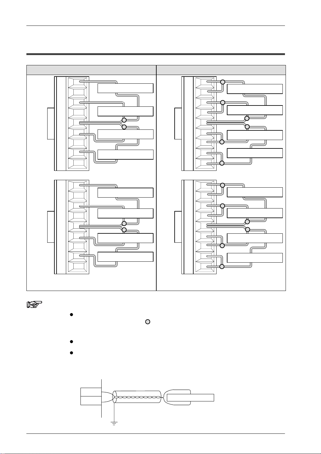
1.2 Analog Input Terminal Block
Pin number Name Description
1V0 Analog input channel 0, voltage input
2I0 Analog input channel 0, current input
3V1 Analog input channel 1, voltage input
4I1 Analog input channel 1, current input
5COM Analog input, input common
6V2 Analog input channel 2, voltage input
7I2 Analog input channel 2, current input
8V3 Analog input channel 3, voltage input
9I3 Analog input channel 3, current input
1V4 Analog input channel 4, voltage input
2I4 Analog input channel 4, current input
3V5 Analog input channel 5, voltage input
4I5 Analog input channel 5, current input
5COM Analog input, input common
6V6 Analog input channel 6, voltage input
7I6 Analog input channel 6, current input
8V7 Analog input channel 7, voltage input
9I7 Analog input channel 7, current input
Notes When the analog input is a current signal, bridge the V and I
input pins externally.
The two COM terminals are connected internally.