Naomoto HSP Series User manual

NAOMOTO
ALL STEAM IRON
HSP series
INSTRUCTION MANUAL
HSP - 440

INTRODUCTION
We thank you for your purchase of NAOMOTO
Model HSP-440 All Steam Iron.
This Instruction Manual is a guide book for
correct use of this iron. Please read this booklet
carefully before using the iron to ensure its
longest possible life.
This iron features our own Condensate Return
System design and is named the “All Steam
Iron’ as it has no electric heater built-in.
We would like you to become familiar with the
outlined structure and functions of the iron so
that you can operate it correctly and efficiently
to your satisfaction.
NOTES
1. In order to ensure safe and prolonged use of
the iron, it is essential that it is used correctly
and that regular maintenance checks are
carried out. Before undertaking any operation
and maintenance work, please read this
manual carefully as well as other manuals of
related machinery such as ironing tables, etc.
that may be used in conjunction with the iron. If
the iron is defective in any way, please contact
the nearest Naomoto office or agent.
2. If the iron is resold or rented to a third party,
please ensure that this manual accompanies
the iron. If the manual is unavailable, ask us for
an extra copy.
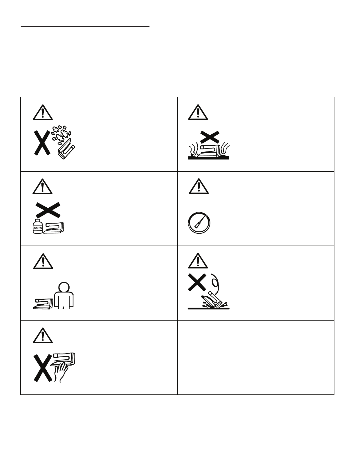
3. In this manual, those actions or conditions
that may cause a fatal accident and/or fire are
marked ”WARNING”, and those that may
cause a breakage and or malfunction of the iron
as well as damage to the fabrin or garment
being worked on are marked “CAUTION”.
4. We do not take any responsibility for injury or
damage arising as a result of the user’s
negligence of the instructions in this manual,
particularly those areas marked as “WARNING”
and “CAUTION”. Any such damage or injury is
not covered under the terms of the warranty.
5. Please note that, as a result of our ongoing
vigorous efforts to improve our products, some
specifications of the machine you have
purchased may slightly differ from those
mentioned in this manual.
CONTENTS
1. SPECIFICATIONS........................................1
2. ATTACHMENTS & ACCESSORIES..............1
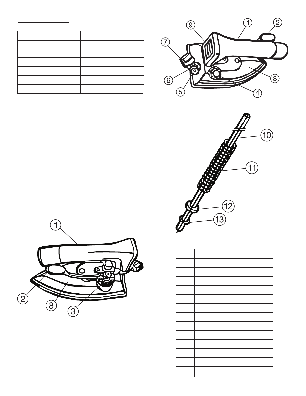
3. NAMES OF COMPONENT PARTS..............1
4. PRECAUTIONS BEFORE OPERATION........2
5. INSTALL & ASSEMBLE................................3
6. IRONING OPERATION.................................5
7. MAINTENANCE & CHECKING....................6

1. SPECIFICATION
MODEL
WORKING STEAM
PRESSURE
STEAM VALVE
WEIGHT
BASE-PLATE SIZE
BODY TREATMENT
HSP-140
0.1 — 0.5 MPa
(1 — 5 bar)
PUSH LEVER TYPE
1.1 kg
203mm X 99mm
“TUFRAM”
2. ATTACHMENT & ACCESSORIES
The following attachments and accessories
are packaged in the same carton as the Iron.
1. 1 pc. Silicone Iron Rest
2. 1 pc. Mesh Filter
3. 2 pc. Packing
4. 1 pc. Inner Tube
5. 1 pc. O- Ring (P- 4)
6. 1 pc. O- Ring Stopper
7. 1 pc. Joint Spring
8. 1 pc. Instruction Manual (This booklet)
3. NAMES OF COMPONENT PARTS
No. Name
1 Urethane Grip Handle
2 Push Lever
3 Steam Valve
4 Steam Supply Hose Joint
5 Drain Hose Joint
6 Drain Valve
7 Knob of Drain Valve
8 Plastic Full Cover
9 Name Plate
10 Inner Tube (Ø 3-Ø 4 Dia)
11 Hose Joint Spring
12 O-Ring Stopper
13 O-Ring (P-4)

4. PRECAUTIONS BEFORE OPERATION
4.1 Application
This iron is intended to be be used exclusively for the ironing of textile fabrics and/or garments.
Please do not use it for any purpose other than the above-mentioned.
This iron is for professional and industrial use, not for household use, and it requires steam supplied
from a steam-boiler.
4.2 Warning & Cautions in General
WARNING
Hot steam is gushing from iron!
Do not hold iron upside down
nor directly toward any person.
CAUTION
Do not apply the iron to any
materials other than textile
fabrics. Some materals may
easily melt, scorch and/or
deform with heat.
WARNING
Do not place inflammables,
chemicals or oils and fats near
the iron at any time.
CAUTION
Provide steam of an appropriate
pressure under 0.5 MPa (5 bar)
for the iron according to the
particular fabric to be worked on.
0.5
MPa
WARNING
Be sure to cut the steam source
for the iron before leaving the
iron unattended.
WARNING
Iron is hot.
Do not touch any part of the
iron other than the iron grip
with bare hands.
CAUTION
Do not drop iron as it may
cause injuries and/or damage.
Always place it securely on the
ron-rest

Inside Cross
Section
Insert tip of the Teflon - Hose into this hole.
5. INSTALL & ASSEMBLE
When setting up the iron, be sure also to
read carefully instruction manuals of related
equipment such as the boiler and ironing
table beforehand
5.1 Set Up of Hoses
- 2 (two) hoses for steam-supply and drain are
required for this iron. Please purchase each
exclusive hose.
If the Inner-Tube is needed to avoid drain
water. It is necessary for minor diameter of
internal of the steam-supply hose to be more
than 5mm at the narrowest part (mouthpiece
part).
5.2 Installation of Hoses
CAUTION
Please do not use any other steam
supply hose than the Naomoto Extra-
Hose especially for steam pressure that
does not exceed 0.3 MPa (3 bar). Naoflon hose
should be used for the drain hose. Use of a non-
genuine hose of which proof pressure is not
confirmed may cause malfunction.
Before setting the Special Extra-Hose to the
iron, clean the inside of the hose by washing
out any dust and dirst. To do this, first fix the
Special Extra-Hose to the boiler, then open
the boiler’s steam valve, and steam flow will
wash out dust and dirt.
CAUTION
While the above cleaning work is being
carried out, place a receptacle (like the
NAOMOTO cartridge-type water tank at
the open end of the Extra Hose to catch the flow
of steam gushing out. Do not touch the Hose with
bare hands as it can be extremely hot. In addition,
take care not to get scalded by the gushing steam
No. Name
1 NAOFLON EXTRA HOSE
2 Inner Tube
(Teflon Hose with Dia. 3-4 mm.)
(Lengthen hose more for more drain water)
3 Hose Joint Spring
4 O-ring Stopper
5 Silicone O-ring (P-4)
When water drops do not come out of the iron
while steaming, above inner tube is not
necessary.
- Installation of the Steam Supply Hose
Insert the inner tube(2) into the hose joint
spring(3), the O-ring stopper(4) and the
O-ring(5), then insert the tube-tip into the
back hole in the steam supply hose joint
of the iron.
1
2
3
4
5

Steam Pipe
Valve
Packing
Mesh-filter
Drain Pipe
Steam Supply Hose
Valve
Check Valve
Steam Trap
Packing
Drain Pipe
CAUTION
• Please do not mistake the drain joint for
the steam supply joint.
• When fastening or unfastening the cap
nut of the Extra-Hose with a spanner, be sure to
hold the hex-part of hose joint on the iron firmly
with another spanner.
CAUTION
Failure to use the mesh-filter will cause
suction of dust and impurities into the
iron together with steam which may give
rise to malfunctions and problems with the iron.
WARNING
The iron reaches a high temperature after
the steaming, so be sure to place it on
the iron-rest, and never place it directly
on the ironing table or by the flammables.
Insert the other end of the inner tube into the
mouth piece (G1/4) of the steam supply hose.
Screw the cap but of the hose to the joint of
the iron and fix it.
- Installation of the Drain Hose
Connect the mouth piece (G1/4) of the drain
hose to the drain hose joint of the iron and fix it.
- Connection of the steam supply hose to a
steam boiler or a central piping system
Connect the end of the steam supply hose to
the steam intake of the boiler.
Before screwing in the nut, be sure to place the
supplied mesh-filter and packing in the steam
intake of the boiler.
Connect the end of the drain supply hose to the
drain intake of the boiler. If a NAOMOTO
NBC-series light-type boiler is used, be sure to
place a gasket (black color) and mesh-filter in
the condensate return inlet of the boiler before
connecting the return hose to it. They are
available as option.
- Place the Iron
Please see that the iron is placed on the
supplied iron-rest when not in use.
The following drawing is an example to connect
to central piping system:
Extra - Hose
Mesh Filter &
Packing ser
Steam Inlet
Condensate Return
Inlet
NAOMOTO NBC Boiler
NAOMOTO NBC Boiler

CAUTION
Be sure to set the drain valve to be
opened fully (c) to use a condensate
return device or a steam trap
6. IRONING OPERATION
When starting and finishing operation, follow
the instructions below. To ensure the correct
operation of the iron, read also the instruction
manual of the boiler, which is to be used with
the iron
6.1 General Advise
- Check the pressure of the boiler by its
pressure gauge and open the steam valve
of the boiler.
- Adjustment of the iron drain valve.
This valve is not completely closed, so there is
clearance with condition of above (c), draining
is possible
(a) Full Open
0.1 MPa
(b) Half Open
0.2 MPa
(c) Closed
More than 0.3 MPa
6.2 Start of Operation
Push the push lever to start steam. At first,
water drops may come out with steam, good
steam comes out in a minute with the
condition of appropriate draining.
CAUTION
Sole plate temperature of all steam iron
as this product is controlled by the steam
pressure of the boiler. Refer to the table
shown below, and check the steam pressure.
However, this table is reference materials, so, the
value on the table are not guaranteed.
Steam
Pressure (MPa)
0.1
0.2
0.3
0.4
0.5
Steam
Temp. (°C)
120
133
143
151
158
Sole Plate
Temp. (°C)
113
125
135
142
149
6.3 At the End of Daily Operation
- Close the steam valve of the boiler.
- Open draining valve fully, then keep the lever
pushing down until all the remaining steam
and water inside the iron and hose have
been blown out.
To start new operation, begin it according to
the START instructions.

7. MAINTENANCE & CHECKING
In case any problems occur with the iron or the boiler, contact the nearest NAOMOTO office or agent
from whom you purchased the equipment.
In order to ensure your equipment is trouble-free, it is important to operate it correctly and also to
keep up regular maintenance checks. Please observe the following procedures.
7.1 Daily Maintenance & Checking
- Clean the iron by removing dust and adhered starch-residues.
- Empty completely remaining steam and condensate in the iron and the hose.
- Check and confirm that there is no steam leakage at the base-plate and the valve while the
swing-lever is in normal posiyion (i.e. the valve is closed).
7.1 Troublehooting
- If you have any problems with the equipment, please check the symptoms and take necessary
countermeasures outlined below where applicable.
- If you need to replace any parts, ask the nearest NAOMOTO office or its agent for the replacement
parts.
WARNING
Before making any checks or carrying out any maintenance work on the iron, be sure to cut the steam
source and empty out any steam from the iron and the steam hose, then wait until the iron cools down.
- Inconsistent Steam Flow
- In case steam valve cannot be closed enough
to stop the steam flow, replace the valve
spindle with a new one.
- Also, ascertain that there is no dust or flaw
with each packing, valve seat, O-ring, washer
etc. In case any part is found damaged,
replace it with a new one.
- Disassemble the valve.
- Insert a wire of dia 1.5mm into the valve
spindle while pushing the lever.
- Unscrew 3 stopping screws of the lever, then
remove push lever and metal fitting.
Push Lever
Adjuster Screw
Set Screw
Set Screw
Valve Spindle

- Adjustment of Steam-Flow
This type of iron is so designed that the
steam-flow from its base-plate can be
adjusted. As shown in the following picture,
first unfasten the plastic nut on top of the
steam valve. Then, the steam-flow can be
decreased by turning the control-screw
clockwise with a s screwdriver, and vice versa
- Remove valve joint with spanner.
- Further, remove wire, teflon bushing, O-ring,
spindle washer and spring on this turn (see
below drawing).
- After finishing checking and replacement,
assemble on the reverse turn.
- When assembling finished, install it on the
iron as follows:
- Insert the wire into the spindle again.
- Install the metal fittng and the lever at last.
Note:
When assembling, be sure to wind the seal
tape on the valve joint
Valve Joint
Copper Packing
Teflon Bushing
O - Ring (P6)
Cap Seal
Spindle Washer
Valve Spring
Valve Spindle
Push Lever
(ie. the steam-flow can be increased turning
the screw counter-clockwise).
Back-up Ring (Wht.)
Plastic Nut
Decrease Increase
Be sure to refasten the plastic nut after the
adjustment is completed. Please note that the
above adjustment is solely intended for
precision control of the steam-flow from the
iron base-plate, this is completely separate
from the steam pressure adjustment on the
boiler.
- Drain
if water drops or much drain come out with
steam, check and treat as follows.
- Abnormal pressure of the steam boiler.
Consult your agent or our office.
- Pipe line abnormality occured.
Consult our office.
- Inconvenience of draining function occured.
Consult our office or refer to drawing below
and check the drain valve.
Drain Valve Body
Copper Packing
Spindle
Jam Nut
O-Ring(Viton) (Blk.)
O-Ring(Silicone)(Pnk.)
Spindle Sopper Screw
Drain Valve Knob
This manual suits for next models
1
Table of contents