NAPCO iSeeVideo ISVWLCAM User manual

1
NAPCO iSeeVideo
ISVWLCAM
Installation Guide
WI1882 08/10
333 Bayview Avenue
Amityville, New York 11701
For Sales and Repairs, (800) 645-9445
For Technical Service, (800) 645-9440
Publicly traded on NASDAQ Symbol: NSSC
© NAPCO 2010
Designed exclusively for use with NAPCO iSeeVideo VideoAlert.net Server
COMPATIBLE
R
Internet
VideoAlert.net SERVER
ISVWLCAM
ISVWAP
Internet
Fixed Wireless IP Camera

2
Table of Contents
Features and specifications ..............................2
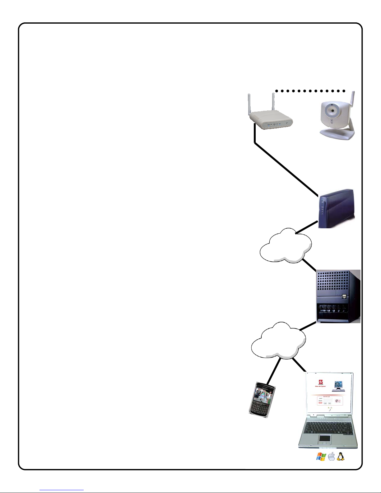
System Overview ...............................................3
Configuring the wireless connection ..................4
Securing the wireless connection ......................4
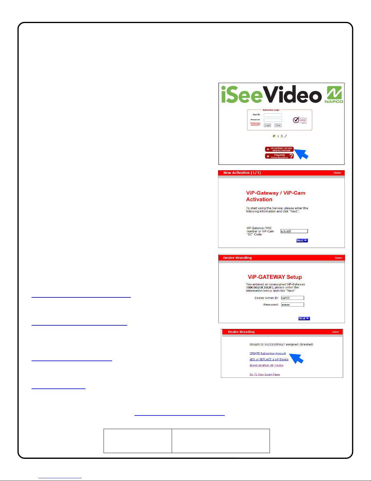
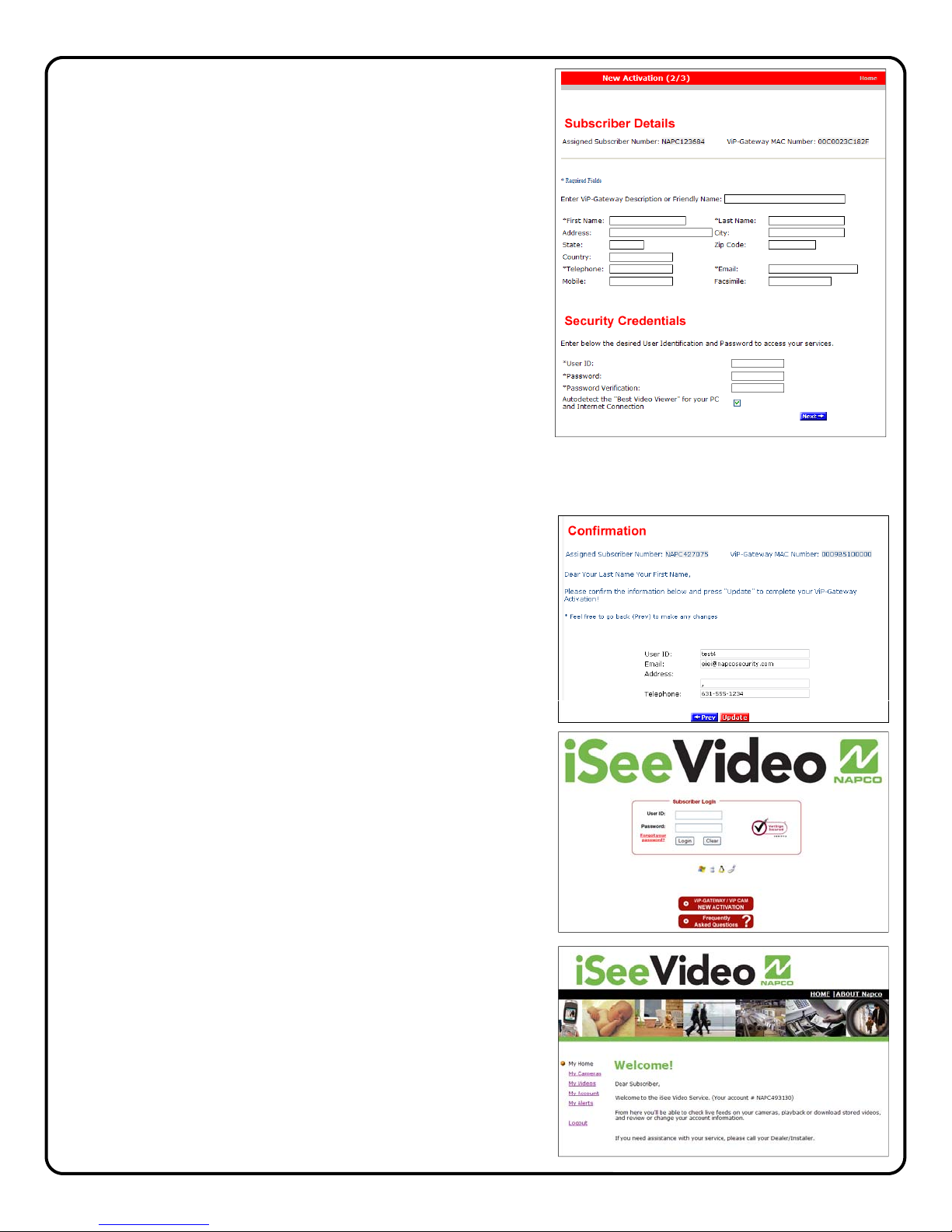
Account Activation..............................................6
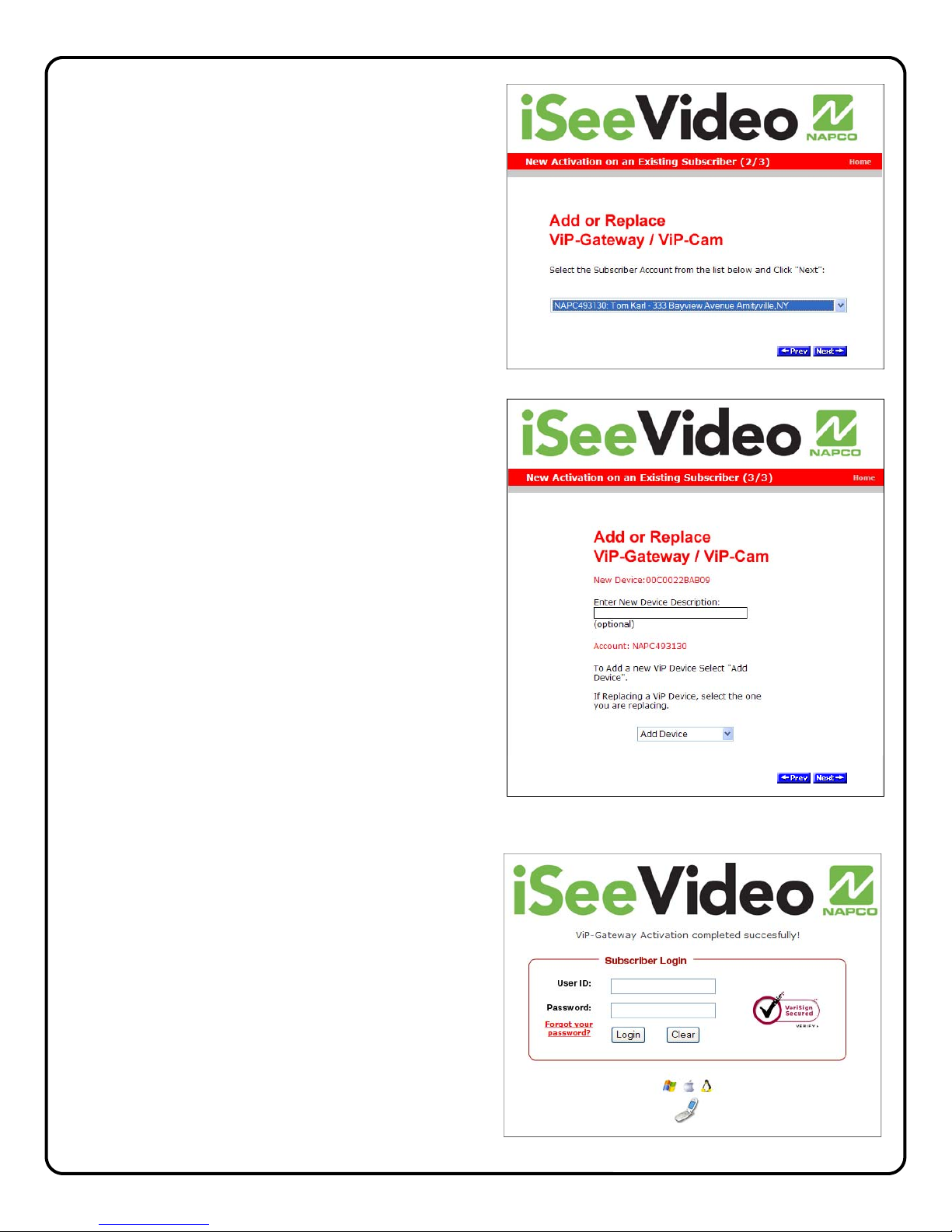
Adding Cameras to an Existing Account............8
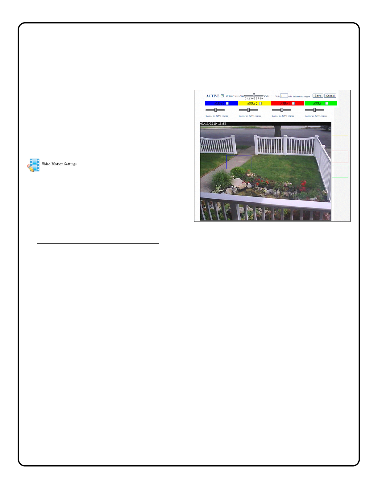
Configuring Motion Detection...........................10
Advanced Settings ...........................................11
Setting a Motion Schedule ...............................11
Viewing Stored Video.......................................11
NAPCO Limited Warranty ................................12
NAPCO Security Technologies, Inc.
For Sales and Repair, call toll free: (800) 645-9445
For direct line to Technical Service,
Ccall toll free: (800) 645-9440
Internet: http://www.napcosecurity.com
Windows ®, and the Windows logo are registered trademarks of Microsoft Corporation
Apple ® and the Apple logo are registered trademarks of Apple Computer, Inc.
Linux ® is a trademark of Linus Torvalds. The Linux penguin logo was created by Larry Ewing.
ISVWLCAM Features
• VGA Resolution (640 x 480) at up to 25 Frames-per-
second
• CMOS, 1/4” VGA Resolution Image Sensor
• Lens F2.0Fixed Focus, Effective Range: 0.2M to infinity
• Resolution Support 640x480
• Image Control AWB, AGC, Sharpness, Brightness
• (4) Programmable Pixel Based Motion Detection Zones
• Compression MPEG-4/M-JPEG Dual Stream
• LED Indicators Power and Network
• Connectors: Ethernet RJ-45, DC Power, Speaker Out,
Reset
• Power Adapter” 5V/1A, 100/240 VAC
• Dimensions (HxWxD) 96 x 90 x 36 mm (3.8” x 3.5” x 1.4”)
• Weight 131g (0.29lb.) without stand, 256g (0.56lb.) with
stand
• Certification CE/FCC
ORDERING INFORMATION
ISVWLKIT1 Fixed IP WL Camera Kit
Includes:
(1)ISVWLCAM, fixed IP wireless camera, mount-
ing bracket, Power Adapter with 15’ cable
(1)ISVWAP, wireless access point, CAT5 cable,
Power Adapter.
12 months iSeeVideo network service
ISVWLCAM Additional Fixed IP WL Camera
Includes:
(1)ISVWLCAM, mounting bracket, Power Adapter
with 15’ cable
12 months iSeeVideo network service
ISVWLPTKIT2 Pan/Tilt IP Camera Kit
Includes:
(1)ISVWLCAMPT, pan/tilt IP wireless camera,
mounting bracket, Power Adapter with 15’
cable
(1)ISVWAP, wireless access point, CAT5 cable,
Power Adapter.
12 months iSeeVideo network service
ISVWLPTCAM Additional Pan/Tilt IP Camera
Includes:
(1)ISVWLCAMPT, mounting bracket, 15’ CAT5
cable, Power Adapter with 15’ cable
12 months iSeeVideo network service
ISVWLOKIT3 One Outdoor IR IP Camera Kit
Includes:
(1)ISVWLCAMPT, Outdoor IR wireless IP camera,
mounting bracket, Power Adapter with 15’
cable
(1)ISVWAP, wireless access point, CAT5 cable,
Power Adapter.
12 months iSeeVideo network service
ISVWLOCAM Additional Outdoor IR IP Camera
Includes:
(1)ISVWLOCAM, Outdoor IR wireless IP camera,
mounting bracket, Power Adapter with 15’
cable
12 months iSeeVideo network service

3
Overview of the iSeeVideo System
Internet
Internet
VideoAlert.net
Server
Customer's
Broadband
Modem
The NAPCO iSeeVideo system allows remote video internet monitoring of
homes and businesses through a unique subscription based account system
that provides the opportunity to realize recurring revenue from residential and
commercial video installations. The system is comprised of the following
components:
The ISVWLCAM high quality wireless IP video camera provides video at 640 x
480 lines of resolution that can be viewed through the iSeeVideo server on
virtually any computer in the world at 20+ frames per second. The ISVWLCAM
also provides pixel based motion detection that when activated will prompt the
transmission of video clips to the iSeeVideo server. The ISVWLCAM provides
(at no additional service charge) dynamic IP support through the iSeeVideo DNS
network - keeping constant track of the broadband modem’s IP address
changes, ensuring that the DHCP IP address is always kept current.
The 640 x 480 VGA resolution at 20 + fps provided by the camera is far superior
to most competitors in the category who offer low quality 240 x 320 video at a
reduced frame rate. This extremely efficient use of available bandwidth allows
you to offer your customers the highest quality video in the category; video that
can even be displayed on a large screen television with remarkable clarity.
The ISVWAP Wireless Access Point allows the simple instant configuration of
the wireless iSeeVideo camera, without confusing or intrusive multi-step
enrollment procedures (patents pending).
The installation procedure for the WAP and cameras is actually not a procedure
at all; simply plug the WAP into the customer’s network (router) and power up
the cameras. At this point, all of the cameras are fully operational and can be
viewed through the iSeeVideo portal, protected by the default iSeeVideo 128bit
encryption. Once all cameras are up and running, simply click the LOCK icon on
the portal to prompt the camera to send a new, unique 128bit encrypted secure
key to the WAP, ensuring the best possible wireless security.
This is unlike competitive installation procedures, which involve confusing
multiple steps with specific precision timing, or in some cases force the installer
to use the customer’s personal computer to “discover” the cameras and
download “plug-ins” through the computer in order to enroll a required gateway.
The iSeeVideo system was designed to avoid all of these obvious complications
and privacy concerns. The customer’s personal property should never be used
as an installation tool, especially when the computer contains the customer’s
personal data including communications, pictures and banking.
The NAPCO iSeeVideo server maintains video accounts and allows
subscribers to view their iSeeVideo cameras from any personal computer, web
enabled cell phone or mobile device. It is compatible with computers running
the Microsoft Windows®, Apple®and Linux®operating systems and is also
compatible with any web enabled cell phone or mobile video device. The server
also automatically notifies the subscriber by email upon receipt of triggered
video events and archives them for viewing at a later time. Each subscriber
account provides 50Mb of storage, allowing the archiving of about (75) 10
second video clips (adjustable 5 sec pre-alarm and 5 sec post-alarm). The
server is designed to allow the customer to have complete control of their
account in regard to passwords, email addresses and other personal
information.
ISEE-VCAM1
ISVWAP

4
⇒ Make the connections above and plug in the ISVWAP power adaptor
⇒ Attach the antennas to the camera(s)
⇒ Plug in the camera power adaptor
There are no other steps required to deploy the cameras through the customer’s network; the cameras will automati-
cally begin communicating to the iSeeVideo server system.
Create the new iSeeVideo account and register the cameras as shown on page 5.
Secure the iSeeVideo Wireless network
Once all cameras have been registered to the new account and can be
viewed, the wireless network must be secured.
⇒ While viewing each camera, simply click Secure Now! next to the
unlock Icon and the camera will send a new, unique 128bit en-
crypted secure key to the Wireless Access Point, providing a se-
cure wireless connection.
⇒ You will be automatically logged out of the account; log back in to
view the secured camera to ensure that the unlock icon has
change to a locked state.
⇒ Repeat for each camera in the system.
If a new camera is added to the system in the future, simply repeat the
above procedure to secure it.
1CONFIGURE THE NETWORK CONNECTION
ISVWLCAM
ISVWLCAMPT
RESET
WAN 4 3 2 1
POWER
TYPICAL ROUTER REAR PORT
ARRANGEMENT
WAN 4 3 2 1
12V/1A
ISVWAP REAR PORTS (DO NOT USE WAN PORT)
CUSTOMER'S
BROADBAND
CONNECTION
(MODEM OR
NETWORK)
CUSTOMER'S
ROUTER
CUSTOMER’S PC
WAN
ISVWAP
ISVWLOCAM

5
NEW ACTIVATION
1. To activate your new iSeeVideo account, simply enter
the following Internet address in your Web browser:
https://www.videoalert.net/
...and the following webpage appears:
Click the NEW ACTIVATION button
The New Activation screen will appear. Enter the 8
character Security Code printed on the label on the
back of the camera.
S C _ _ _ _ _ _
Click Next
2. The Dealer Branding screen will appear. Enter your
Company Dealer Admin ID and Password and click
Next
When Dealer Branding is successful, a screen offering the
following options will appear:
Create Subscriber Account Now
Click to create a new Subscriber account with this camera
and enter the Subscriber details (see below)
ADD or REPLACE a VIP Device
To add or replace a camera to the account click here. See
Adding additional cameras to an existing account for more
details.
Brand Another VIP Device
If there are multiple cameras to be installed, click here to
brand these devices
Go to Login Page
Click here to go directly into your camera log-in screen.
For a single camera system, click CREATE Subscriber Account
2Activating the iSeeVideo account
Following are the steps for account activation. These activation steps include the branding of the cam-
era to your Company’s personalized iSeeVideo web page, registration of the camera and adding Us-
ers to the account.
ISVWLCAM
Security Code S C _ _ _ _ _ _

6
3. Create Subscriber Account Now
Click to bring up the Subscriber Details screen, where the
basic account information is entered.
Enter your name, address, telephone number and other
information in the appropriate fields as shown in the image
at right.
The User ID and Password entered at this step will be-
come the Master User of the account and will be the only
User to have administrative privileges (the ability to pro-
gram Advanced Settings and add Users to the account)
NOTE: All field descriptions marked with an asterisk (*)
must be completed.
! IMPORTANT - Change your Password
Click Next
4. Confirmation
The "Confirmation" section verifies all information en-
tered above.
Be sure to check the accuracy of the information dis-
played, and if changes are required, click the Prev button
to edit any previously entered information.
When you are sure the information displayed is correct,
click the Update button to complete your new account
activation procedure.
)If you forget your password, click the "Forgot Your Pass-
word?" link on the Subscriber Login screen and an email
with your password will be sent to the email address above.
5. Login Screen
The iSeeVideo login screen will appear. Test the ac-
count by logging in with the new User ID and Pass-
word.
6. Welcome screen
If login is successful, the Welcome screen will ap-
pear. This is the User’s “Home” screen, and will allow
them to manage their account, view cameras and
stored video.

7
7. My Account
Click My Account to view account information. From
this screen, you can update your account information
(My Information), and add Users to the account.
To add a new User to the account, click Add a New User.
8. Adding additional Users. To add User to the account,
click Add a New User and the User Details screen
opens, allowing you to add new users in the fields
shown. Note: All fields are required.
Enable (check) Authorize Live Video Review if to al-
low the user to view live video sat any time.
By default, Auto-detect “Best Video Viewer...” should
always be enabled.
Click Update to add the new user and return to the pre-
vious screen, or click Prev to cancel and return to the
previous screen.
The system supports a maximum of 5 Users, including
the Primary User.
9. Click Email Alert Settings to enter the email address
of those Users you wish to be notified via email when a
triggered motion detection event occurs. The email
message will include a link to the account and will allow
them to review stored video. The system supports a
maximum of 5 Users, including the Primary User.
You may also enter the subject you would like the User
to see on the Subject line of the email, as well as text
in the message body.
To activate the video motion detection feature, see
page 10.

8
1. Return to the www.videoalert.net login
screen and click the NEW ACTIVATION button
The New Activation screen will appear. En-
ter the 8 character Security Code printed
on the label on the back of the camera to
be added.
S C _ _ _ _ _ _
Click Next
2. The Dealer Branding screen will appear.
Enter your Company Dealer Admin ID and
Password and click Next
3. After Dealer Branding is complete, click Add
or Replace a VIP Device.
Adding or Replacing cameras on an existing account.
Once the camera has been registered and the account has been created, additional cameras, if any may
be added to the account through the following steps:

9
4. The next screen that appear will allow the
registration of the camera to the correct
account. A pull-down menu will appear,
listing all accounts assigned to the Dealer
ID entered in the branding screen.
Select the correct account from the list by
clicking it and then click Next to
continue.
5. The following screen allows the entry of
the camera description in the Enter New
Device Description field.
Click the pull-down menu and select Add
Device to complete the addition of the
new camera to the account.
NOTE: If replacing a VIP Device assigned
to the account, select from the pull-down
menu the device you wish to replace.
Click Next to continue.
6. When the activation is complete, the log in
screen will appear, with the message “VIP
Activation completed successfully!”

10
4CONFIGURING THE ISVWLCAM
Once the ISVWLCAM(s) have been and powered up, and the account has been activated, the cameras
may be configured. The next several pages will guide you through the on-line configuration process.
Note: If the cameras are only to be used for live viewing and there are no plans to trigger video motion
events to the server, configuration is not required.
MOTION DETECTION (OPTIONAL)
The ISVWLCAM supports pixel-based motion de-
tection which allows the camera to send motion
triggered video clips to the VideoAlert.net video
server upon motion in a selected area.
To configure the camera for motion
detection, enter Video Motion Set-
tings mode my clicking the Video
Motion icon and the screen Video
Motion Settings screen will appear.
Click the Active box to enable pixel-based motion
detection. To set a motion detection window, click
the colored box on the right and drag the window
into the live image.
Simply drag the window to a specific section of the live view screen and size it appropriately by pressing
SHIFT and dragging a side of the window. Once the window is properly positioned and sized, the sensitiv-
ity threshold can be set by dragging the corresponding threshold slider to the left for less sensitivity and to
the right for more.
The camera has the ability to store video recorded before the actual sensing of motion. Use the PRE
and POST slider control to adjust the Pre-Capture Length and Post-Capture Length setting, with Pre-
Capture Length being the length of video captured before the actual sensing of motion and the Post-
Capture Length being the length of the video after the sensing of motion.
Use the slider control for each respective Area box to adjust the sensitivity of the pixel based motion detec-
tion, with 100% being the highest sensitivity and 0% being the lowest.
When settings are complete, click the Apply/Save and then click the camera name above the live view to
exit.
Note: Motion detection analyzes the video and detects changes in the pixel properties. It is important that
the detection windows enabled be limited to only areas of anticipated activity. If using motion detection out-
doors, changes in pixels may be caused by blowing tree branches, shrubs, sun / shade changes caused by
changing cloud cover, etc. To avoid nuisance triggers, exclude these areas of concern from the enabled
detection area.
Programming Motion Detection Schedules
If desired, the Motion Detection feature may be controlled by schedule, allowing the user to set a specific
time and day for motion detection and email triggering. This will prompt the system to capture video clips
and send email notifications only if motion detection is sensed during the scheduled time period.
To program schedules, go to the live viewer and click the Advanced Settings icon and the advanced fea-
tures screen will appear. Turn to page 11

11
ADVANCED SETTINGS
To enter Advanced Settings, click the tool icon
Firmware Version
The firmware version of the camera will display. If there
is a new version available, a message will display, along
with a button to upgrade to the new version.
Camera Time Zone
Use drop down menu to set the time zone of the cam-
era.
Enable Time Stamp
To enable a time and date stamp on the live and saved
video, click the check box next to Enable Time Stamp.
Enable Text Display
To provide a Camera Name, click the check box next to
Enable Text Display and enter in the name you would
like to see on the screen.
Flip Video
Enable to invert video in cases where camera is installed
upside down.
Event Schedule
To enable a time schedule for motion detection trigger-
ing, select the desired day(s) in the Effective Time
Frame window. Click Start Time and End Time to se-
lect the start and end time of the motion detection
schedule.
As schedules are programmed, they will appear in the
Event Schedule window.
When done, click Save to save changes.
Viewing of Stored Video
To view stored video clips, click on the My Videos link
and the My Videos page will appear.
For each video, a thumbnail image will appear, along
with a time and date stamp indicating the time and
date of the creation of the file.
The file can be deleted by clicking Delete adjacent to
the file.
The file can also be saved on the hard drive of the
computer being used to view the file by clicking
Download adjacent to the file.
Once the number of video clips stored in the account
reaches the maximum allotted size for the account,
each new file stored will result in the automatic deletion
of the oldest file.

12
NAPCO SECURITY SYSTEMS, INC. (NAPCO) warrants
its products to be free from manufacturing defects in
materials and workmanship for twelve months following
the date of manufacture. NAPCO will, within said period,
at its option, repair or replace any product failing to
operate correctly without charge to the original
purchaser or user.
This warranty shall not apply to any equipment, or any
part thereof, which has been repaired by others,
improperly installed, improperly used, abused, altered,
damaged, subjected to acts of God, or on which any
serial numbers have been altered, defaced or removed.
Seller will not be responsible for any dismantling or
reinstallation charges.
THERE ARE NO WARRANTIES, EXPRESS OR
IMPLIED, WHICH EXTEND BEYOND THE
DESCRIPTION ON THE FACE HEREOF. THERE IS
NO EXPRESS OR IMPLIED WARRANTY OF
MERCHANTABILITY OR A WARRANTY OF FITNESS
FOR A PARTICULAR PURPOSE. ADDITIONALLY,
THIS WARRANTY IS IN LIEU OF ALL OTHER
OBLIGATIONS OR LIABILITIES ON THE PART OF
NAPCO.
Any action for breach of warranty, including but not
limited to any implied warranty of merchantability, must
be brought within the six months following the end of the
warranty period.
IN NO CASE SHALL NAPCO BE LIABLE TO ANYONE
FOR ANY CONSEQUENTIAL OR INCIDENTAL
DAMAGES FOR BREACH OF THIS OR ANY OTHER
WARRANTY, EXPRESS OR IMPLIED, EVEN IF THE
LOSS OR DAMAGE IS CAUSED BY THE SELLER'S
OWN NEGLIGENCE OR FAULT.
In case of defect, contact the security professional who
installed and maintains your security system. In order to
exercise the warranty, the product must be returned by
the security professional, shipping costs prepaid and
insured to NAPCO. After repair or replacement, NAPCO
assumes the cost of returning products under warranty.
NAPCO shall have no obligation under this warranty, or
otherwise, if the product has been repaired by others,
improperly installed, improperly used, abused, altered,
damaged, subjected to accident, nuisance, flood, fire or
acts of God, or on which any serial numbers have been
altered, defaced or removed. NAPCO will not be
responsible for any dismantling, reassembly or
reinstallation charges.
This warranty contains the entire warranty. It is the sole
warranty and any prior agreements or representations,
whether oral or written, are either merged herein or are
expressly cancelled. NAPCO neither assumes, nor
authorizes any other person purporting to act on its
behalf to modify, to change, or to assume for it, any
other warranty or liability concerning its products.
In no event shall NAPCO be liable for an amount in
excess of NAPCO's original selling price of the product,
for any loss or damage, whether direct, indirect,
incidental, consequential, or otherwise arising out of any
failure of the product. Seller's warranty, as hereinabove
set forth, shall not be enlarged, diminished or affected by
and no obligation or liability shall arise or grow out of
Seller's rendering of technical advice or service in
connection with Buyer's order of the goods furnished
hereunder.
NAPCO RECOMMENDS THAT THE ENTIRE SYSTEM
BE COMPLETELY TESTED WEEKLY.
Warning: Despite frequent testing, and due to, but not
limited to, any or all of the following; criminal tampering,
electrical or communications disruption, it is possible for
the system to fail to perform as expected. NAPCO does
not represent that the product/system may not be
compromised or circumvented; or that the product or
system will prevent any personal injury or property loss
by burglary, robbery, fire or otherwise; nor that the
product or system will in all cases provide adequate
warning or protection. A properly installed and
maintained alarm may only reduce risk of burglary,
robbery, fire or otherwise but it is not insurance or a
guarantee that these events will not occur.
CONSEQUENTLY, SELLER SHALL HAVE NO
LIABILITY FOR ANY PERSONAL INJURY, PROPERTY
DAMAGE, OR OTHER LOSS BASED ON A CLAIM THE
PRODUCT FAILED TO GIVE WARNING. Therefore, the
installer should in turn advise the consumer to take any
and all precautions for his or her safety including, but not
limited to, fleeing the premises and calling police or fire
department, in order to mitigate the possibilities of harm
and/or damage.
NAPCO is not an insurer of either the property or safety
of the user's family or employees, and limits its liability
for any loss or damage including incidental or
consequential damages to NAPCO's original selling
price of the product regardless of the cause of such loss
or damage.
Some states do not allow limitations on how long an
implied warranty lasts or do not allow the exclusion or
limitation of incidental or consequential damages, or
differentiate in their treatment of limitations of liability for
ordinary or gross negligence, so the above limitations or
exclusions may not apply to you. This Warranty gives
you specific legal rights and you may also have other
rights which vary from state to state.
NAPCO LIMITED WARRANTY
Other manuals for iSeeVideo ISVWLCAM
1
Table of contents
Other NAPCO IP Camera manuals