NAPCO iSeeVideo ISEE-VCAM1 User manual

1
NAPCO iSeeVideo
ISEE-VCAM1
Installation Guide WI1735A 6/08
333 Bayview Avenue
Amityville, New York 11701
For Sales and Repairs, (800) 645-9445
For Technical Service, (800) 645-9440
Publicly traded on NASDAQ Symbol: NSSC
© NAPCO 2008
Designed exclusively for use with NAPCO iSeeVideo VideoAlert.net Server
COMPATIBLE
R
G-BOX
IP Plug & Play Module
Internet
VideoAlert.net SERVER
ISEE-VCAM1
ISEE-EOP-MOD200
ISEE-EOP-MOD200

2
Table of Contents
Features and Specifications ..............................2
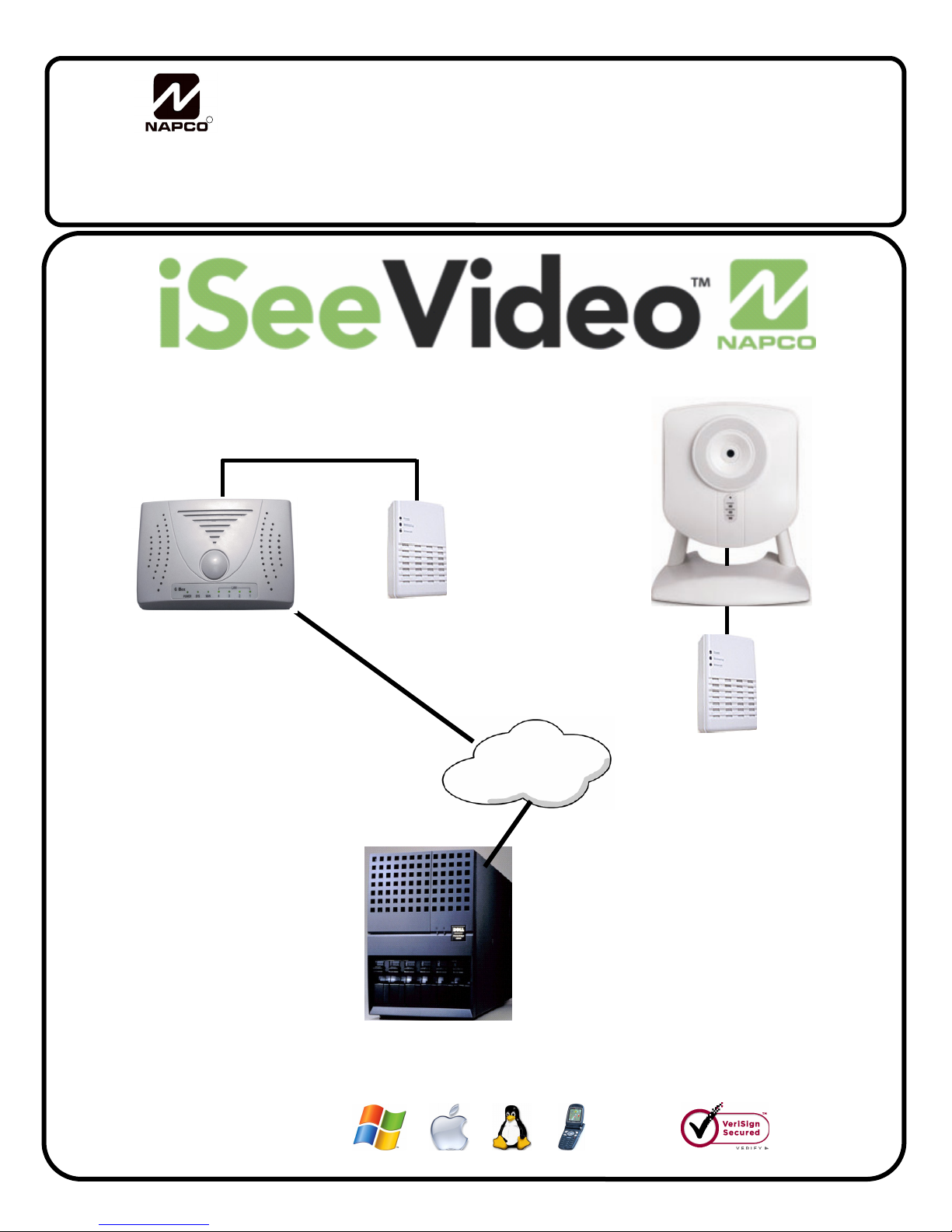
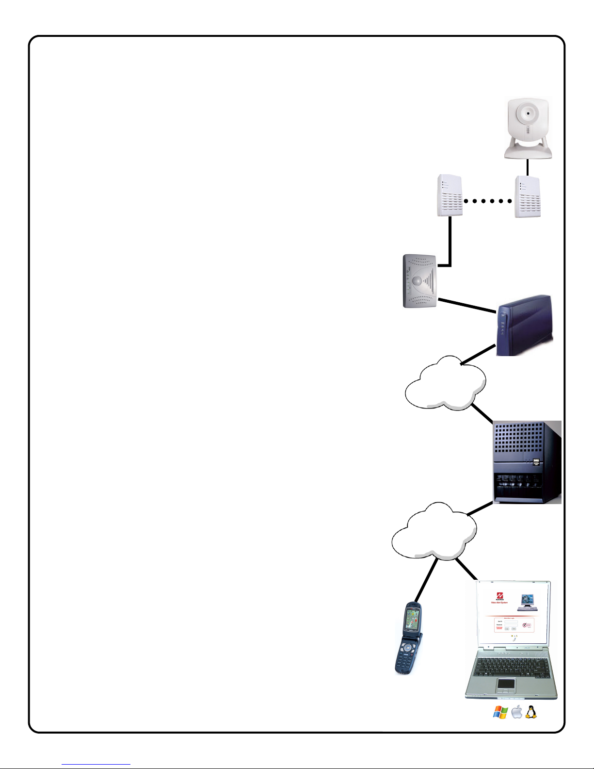
System Overview ...............................................3
Installation Overview ..........................................4
Installing the ISEE-VCAM1 ................................5
Connecting to G-BOX & Internet........................6
G-BOX LED Indicators .......................................6
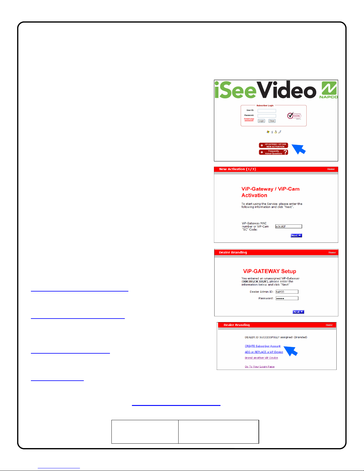
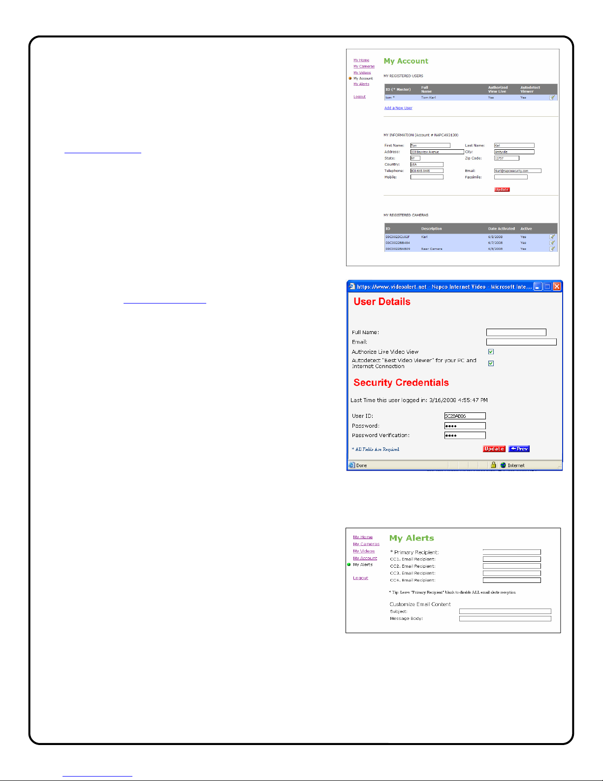
Account Activation..............................................7
Adding Cameras to an Existing Account..........10
Configuring Motion Detection...........................12
Setting a Motion Schedule ...............................13
Viewing Stored Video.......................................14
Setting up the EOP modules............................15
Creating a Secure Network ..............................15
Frequently Asked Questions............................17
Troubleshooting ...............................................18
NAPCO Limited Warranty ................................20
NAPCO Security Systems, Inc.
333 Bayview Avenue, Amityville, New York 11701
For Sales and Repair, call toll free: (800) 645-9445
For direct line to Technical Service,
call toll free: (800) 645-9440
Internet: http://www.napcosecurity.com
Windows®, and the Windows logo are registered trademarks of Microsoft Corporation
Apple®and the Apple logo are registered trademarks of Apple Computer, Inc.
Linux®is a trademark of Linus Torvalds. The Linux penguin logo was created by Larry Ewing.
ISEE-VCAM1 Features
• VGA Resolution (640 x 480) at up to 25 frames-per-second
• CMOS, 1/6" VGA Resolution Image Sensor
• Lens F2.8 Fixed Focus; Effective Range: 0.2M to infinity
• Resolution Support 640x480, 320x240, 160x120
• Image Control AWB, AGC, Sharpness, Brightness
• (4) Programmable Pixel Based Motion Detection Zones
• Compression MPEG-4/M-JPEG Dual Stream
• LED Indicators Power, Active, Network
• Connectors: Ethernet RJ-45, DC Power, Reset
• Power Adapter" 5V/1A, 100/240 VAC
• Dimensions (H x W x D): 96 x 90 x 36 mm (3.8" x 3.5" x 1.4")
• Weight 131g (0.29lb.) without stand, 256g (0.56lb.) with stand
• Certification CE/FCC
ISEE-EOP-MOD200 Features
• Data Rate:...............Up to 200Mbps
• Port: .......................Ethernet,10Base-T/100Base-TX
• LED's .....................Power, Powerline, Ethernet
• Cabling Type:..........Cat5, RJ-45
• Security Feature: ....AES Encryption
• Security Key Bits:....128
• Power:.....................One AC Plug, 100-240V, 50-60 Hz
• Standards: ..............HomePlug AV Standard, IEEE 802.3, IEEE
802.3u
• Compliances: ..........IEEE 802.3, IEEE 802.3u Communications
• Certifications: ..........UL Listed (UL60950-1)/cUL CSA No.22-
60950-01-03, CB, IEC/EN 60950-1;2001. FCC Part 15 Class B,
CE Mark, 89/336/EE.
Dimensions 4 7/8 x 8 1/4 x 1 1/2
(H x W x D), Inches
Input Voltage: 5VDC via 100-240VAC to 5VDC
Transformer (supplied)
Current: 600mA
(Transformer rating)
ISEE-VCAM1 SPECIFICATIONS
ORDERING INFORMATION
VCAM1-EOPKT1/12 One Camera Kit
Includes:
(1) ISEE-VCAM-1, mounting bracket, 15' CAT5
cable, Power Adapter with 15' cable.
(2) ISEE-EOP MOD200, 6' CAT5 cable.
(1) G-BOX, Power Adapter, 3' CAT5 cable
12 months VideoAlert.net service.
VCAM1-EOPKT2/12 Two Camera Kit
Includes:
(2) ISEE-VCAM-1, mounting bracket, 15' CAT5
cable, Power Adapter with 15' cable
(3) ISEE-EOP MOD200, 6' CAT5 cable
(1) G-BOX, Power Adapter, 3' CAT5 cable
12 months VideoAlert.net service
VCAM1-EOP1/12 Additional Camera Kit
Includes:
(1) ISEE-VCAM-1, mounting bracket, 15' CAT5
cable, Power Adapter with 15' cable
(1) ISEE-EOP MOD200, 6' CAT5 cable
12 months VideoAlert.net service
G-BOX SPECIFICATIONS
Dimensions 5 5/8 x 3 3/8 x 1 1/8
(H x W x D), Inches
Input Voltage: 9VAC via 120VAC to 9VAC
Transformer (supplied)
Current: 180mA Max (all 4 LAN ports in
use)
ISEE-EOP-MOD200
SPECIFICATIONS
Dimensions 5.5 x 4.0 x 2
(H x W x D), Inches
Input Voltage: 100-240V AC, 50-60 Hz

3
Overview of the iSeeVideo VideoAlert.net System
Internet
Internet
G-BOX
VideoAlert.net
Server
Customer's
Broadband
Modem
ISEE-VCAM1
ISEE-EOP-MOD200
The NAPCO iSeeVideo VideoAlert.net system allows remote video internet
monitoring of residential and light commercial properties. Its unique
subscription-based account system provides the opportunity to realize
recurring revenue from typical CCTV video installations, The system is
comprised of the following four components:
The ISEE-VCAM1 is a high quality IP video camera that provides video
images with a maximum of 640 x 480 lines of resolution that can be viewed
through the VideoAlert.net server on virtually any computer in the world at up
to 25 fps. The ISEE-VCAM1 provides pixel based motion detection that,
when activated, will prompt the transmission of video clips to the
VideoAlert.net server. The ISEE-VCAM1 provides (at no additional service
charge) dynamic IP support through a DNS server - every time the broadband
modem's IP address changes, it checks in with its DNS server to insure that
the DHCP IP address is always kept current.
The ISEE-EOP-MOD200 is an Ethernet-Over-Power module that allows the
transmission of video signals over the existing power lines of a home or
business. The simple Plug-n-Play installation allows the ISEE-VCAM1 to
communicate with the G-BOX interface module by simply connecting the
devices to their respective EOP modules and then into the electrical outlets.
The modules create a powerline network ideal for the transmission of video
signals at up to 200 megabits per second. The EOP modules are fully capable
of transmitting data across the phases of typical residential multiphase power
systems.
The G-BOX (Patents Pending) is an Internet Video accessory that allows the
"Plug & Play" installation of the ISEE-VCAM1 camera system. Many other
devices that allow direct connection to the internet require re-configuration of
the router, but not the G-BOX. The G-BOX segments the network,
automatically detects and properly forwards the data intended for the ISEE-
VCAM1 or to the customer's computer/router, as required. The G-BOX is
designed to be placed between the broadband modem and router, and also
functions as a router for cases where the customer's PC is the only device
connected to the broadband modem. The G-BOX provides 4 auto-sensing
LAN ports for connection to the ISEE-VCAM1 through the ISEE-EOP-
MOD200 and to the customer's PC, router or other equipment. This
revolutionary new device totally eliminates the need for TCP/IP and network
trained professionals for typical ISEE-VCAM1 installations, now allowing
standard alarm personnel to quickly and easily install these IP devices. The
G-BOX functions as both a DHCP client and server, to fit seamlessly into all
typical DHCP environments.
The NAPCO VideoAlert.net server maintains VideoAlert accounts and allows
subscribers to view their ISEE-VCAM1 camera from any personal computer
or web enabled cell phone. It is compatible with computers running the
Microsoft Windows®, Apple®and Linux®operating systems and is also
compatible with any WAP enabled cell phone or mobile video device. The
server also automatically notifies the subscriber by email upon receipt of
triggered video events and archives them for viewing at a later time. Each
subscriber account provides 50Mb of storage, allowing the archiving of about
(75) 10 second video clips (adjustable 5 sec pre-alarm and 5 sec post-alarm).
The server is designed to allow the customer to have complete control of their
account in regard to passwords, email addresses and other personal
information.

4
INSTALLING, ACTIVATING AND CONFIGURING THE ISEE-VCAM1 AND G-BOX
The installation and activation of the VideoAlert system has been designed to be "plug and play", requiring no special
training or tools and no knowledge of TCP/IP or networking for typical installations. The primary installation steps de-
picted below are covered in detail on the following pages:
1Install the ISEE-VCAM1 cameras and ISEE-EOP MOD200 modules, (page 5)
2Install the G-BOX and its ISEE-EOP MOD200 module. (page 6)
3Activate the new ISEE-VCAM1 account on the VideoAlert server. (page 7)
4Configure the camera for motion detection triggering (Optional) (Page 12).
(Optional) The camera may be configured for motion detection on-line by simply going to www.VideoAlert.net,
and entering the camera security code number printed on the sticker on the bottom of the camera.
BROADBAND
MODEM
CUSTOMERS ROUTER
(OPTIONAL)
G-BOX
CUSTOMER'S PC
FROM BROADBAND
PROVIDER
OVERVIEW OF TYPICAL ISEE-VCAM1 / G-BOX RESIDENTIAL INSTALLATION
(Power connections not shown)
ISEE-VCAM1
ISEE-EOP MOD200

5
1INSTALLING THE ISEE-VCAM1
• The ISEE-VCAM1 camera is designed for table top, wall or ceiling mounting. Install bracket at desired location and
attach the camera body to bracket.
• Plug camera power cable into POWER and CAT5 into LAN jacks.
• Connect the other end of the CAT5 cable to the ISEE-EOP-MOD200 Ethernet-Over-Power module LAN jacks.
• Plug ISEE-EOP-MOD200 module and camera power supply into AC wall outlet
• Repeat for each camera to be installed.
Table top mount Wall mount
Ceiling mount
Note: If AC power-strips
are required due to un-
available AC outlets, non
surge protected or noise
filtered power-strips must
be used. Many AC power-
strips utilize internal surge
protection that may pre-
vent the EOP modules
from operating.
EOP module must
be plugged directly
into wall outlet

6
2WIRE THE G-BOX
CONNECT THE G-BOX TO ROUTER
1. Record the ISEE-VCAM1 Security Code (bottom label, example: SC106763) which will
be needed in the subsequent registration steps:
2. Power-down existing network devices (i.e. Cable Modem, Router, etc.).
3. Connect the Cable or DSL Modem to the G-BOX WAN port.
4. Connect ISEE-EOP-MOD200 to any G-BOX LAN port.
5. If necessary, you may connect existing PC to any available LAN port --OR--if customer
has a router, connect the router WAN port to any available LAN port.
5. Power Up all the devices. Several minutes may be required for the
DHCP sessions to take place.
IMPORTANT: For installations on Cable Internet systems, power
down cable modem for 10 minutes, then power up the complete
system to allow ISP to synch with the MAC address of the G-BOX.
Go to VideoAlert.net Activation on page 7.
Indica-
tor Color Solid Flashing
Power Green
Turns solid green
when power is
applied to device.
N/A
SYS Green Normal Normal
WAN Green
Connected and
linked to a Cable/
DSL Modem.
Receiving/
Sending data
LAN 1
to
LAN 4
Green
Turns green when
linked to a local
network.
Receiving/
Sending data
G-BOX LED INDICATORS
BROADBAND
MODEM
G-BOX
WAN
(INTERNET)
CUSTOMER'S
ROUTER
CUSTOMER'S
PC
)
If no router installed, connect PC
directly to the G-BOX LAN ports
WAN LAN1 LAN2 LAN3 LAN4
Note: G-BOX LAN Ports are auto-sensing. Customer's devices
or the ISEE-EOP-MOD200 may be plugged into any port.
WAN LAN1 LAN2 LAN3 LAN4
ISEE-EOP-MOD200
Note: If AC power-strips
are required due to un-
available AC outlets, non
surge protected or noise
filtered power-strips must
be used. Many AC power-
strips utilize internal surge
protection that may pre-
vent the EOP modules
from operating.
EOP module must
be plugged directly
into wall outlet

7
NEW ACTIVATION
1. To activate your new VCAM Video account, simply type
the following Internet address in your Web browser:
https://www.videoalert.net/
...and the following webpage appears:
Click the NEW ACTIVATION button
The New Activation screen will appear. Enter the 8
character Security Code printed on the label on the
back of the camera.
S C _ _ _ _ _ _
Click Next
2. The Dealer Branding screen will appear. Enter your
Company Dealer Admin ID and Password and click
Next
When Dealer Branding is successful, a screen offering the
following options will appear:
Create Subscriber Account Now
Click to create a new Subscriber account with this camera
and enter the Subscriber details (see below).
ADD or REPLACE a VIP Device
To add or replace a camera to the account click here. See
Adding additional cameras to an existing account for more
details.
Brand Another VIP Device
If there are multiple cameras to be installed, click here to
brand these devices.
Go to Login Page
Click here to go directly into your camera log-in screen.
For a single camera system, click CREATE Subscriber Account
3Activating the VideoAlert.net account
Once the ISEE-VCAM1 and G-BOX have been completely wired and powered up, the VideoAlert.net
account is ready to be activated. These activation steps, include the branding of the camera to your
Company's personalized VideoAlert.net web page, registration of the camera and the adding of Users
to the account.
ISEE-VCAM1
Security Code S C _ _ _ _ _ _

8
3. Create Subscriber Account Now
Click to bring up the Subscriber Details screen, where
the basic account information is entered.
Enter your name, address, telephone number and other
information in the appropriate fields as shown in the im-
age at right.
The User ID and Password entered at this step will be-
come the Master User of the account and will be the
only User to have administrative privileges (the ability to
program Advanced Settings and add Users to the ac-
count).
NOTE: All field descriptions marked with an asterisk (*)
must be completed.
! IMPORTANT - Change your Password
Click Next
4. Confirmation
The "Confirmation" section verifies all information en-
tered above.
Be sure to check the accuracy of the information dis-
played, and if changes are required, click the Prev but-
ton to edit any previously entered information.
When you are sure the information displayed is correct,
click the Update button to complete your new account
activation procedure.
If you forgot your password, click the "Forgot Your
Password?" link on the Subscriber Login screen and
an email with your password will be sent to the email
address listed.
5. Login Screen
The iSeeVideo login screen will appear. Test the ac-
count by logging in with the new User ID and Password.
6. Welcome screen
If login is successful, the Welcome screen will appear.
This is the User's "Home" screen, and will allow them to
manage their account, view cameras and stored video.

9
7. My Account
Click My Account to view account information. From
this screen, you can update your account informa-
tion (My Information), and add Users to the account.
To add a new User to the account, click
Add a New User.
8. Adding additional Users. To add User to the ac-
count, click Add a New User and the User Details
screen opens, allowing you to add new users in the
fields shown. Note: All fields are required.
Enable (check) Authorize Live Video Review if to
allow the user to view live video sat any time.
By default, Auto-detect "Best Video Viewer..."
should always be enabled.
Click Update to add the new user and return to the
previous screen, or click Prev to cancel and return
to the previous screen.
The system supports a maximum of 5 Users, includ-
ing the Primary User.
9. Click Email Alert Settings to enter the Email ad-
dress of those Users you wish to be notified via
email when a triggered motion detection event oc-
curs. The email message will include a link to the
account and will allow them to review stored video.
The system supports a maximum of 5 Users, includ-
ing the Primary User.
You may also enter the subject you would like the
User to see on the subject line of the email, as well
as text in the message body.
To activate the video motion detection feature, see
page 13.

10
1. Return to the www.videoalert.net login screen
and click the NEW ACTIVATION button.
The New Activation screen will appear. Enter the
8 character Security Code printed on the label on
the back of the camera to be added.
S C _ _ _ _ _ _
Click Next
2. The Dealer Branding screen will appear. Enter
your Company Dealer Admin ID and Password
and click Next
3. After Dealer Branding is complete, click Add or
Replace a VIP Device.
Adding or Replacing cameras on an existing account.
Once the camera has been registered and the account has been created, additional cameras, if any may
be added to the account through the following steps:

11
4. The next screen that appear will allow the regis-
tration of the camera to the correct account. A
pull-down menu will appear, listing all accounts
assigned to the Dealer ID entered in the branding
screen.
Select the correct account from the list by clicking
it and then click Next to continue.
5. The following screen allows the entry of the
camera description in the Enter New Device De-
scription field.
Click the pull-down menu and select Add De-
vice to complete the addition of the new camera
to the account.
NOTE: If replacing a VIP Device assigned to
the account, select from the pull-down menu the
device you wish to replace.
Click Next to continue.
6. When the activation is complete, the log in screen
will appear, with the message "VIP Activation
completed successfully!"

12
CONFIGURATION
1. To configure the new ISEE-VCAM1, simply
enter the following Internet address in the
Web browser:
http://www.VideoAlert.net
...and the following webpage appears:
Log in to your account, type your
Username and Password.
4Configuring the ISEE-VCAM1 for Motion Detection (Optional)
Once the ISEE-VCAM1 and G-BOX have been completely wired and powered up, and the account has
been activated, the ISEE-VCAM1 may be configured. The next several pages will guide you through the
on-line configuration process.
Note: If the ISEE-VCAM1 is only to be used for live viewing and there are no plans to trigger video mo-
tion events to the VideoAlert.net server, configuration is not required.
2. Click on My Cameras and a Live image from the ISEE-VCAM1 appears.

13
ADVANCED FEATURES (OPTIONAL)
The ISEE-VCAM1 supports pixel-based motion
detection which allows the camera to send motion
triggered video clips to the VideoAlert.net video
server upon motion in a selected area.
To configure the camera for motion
detection, enter Video Motion Set-
tings mode my clicking the Video
Motion icon and the screen Video
Motion Settings screen will appear.
Click the Active box to enable pixel-based motion
detection. To set a motion detection window, click
the colored box on the right and drag the window
into the live image.
Simply drag the window to a specific section of the live view screen and size it appropriately by pressing
SHIFT and dragging and dragging a side of the window. Once the window is properly positioned and
sized, the sensitivity threshold can be set by dragging the corresponding threshold slider to the left for less
sensitivity and to the right for more.
The camera has the ability to store video recorded before the actual sensing of motion. Use the PRE
and POST slider control to adjust the Pre-Capture Length and Post-Capture Length setting, with Pre-
Capture Length being the length of video captured before the actual sensing of motion and the Post-
Capture Length being the length of the video after the sensing of motion.
Use the slider control for each respective Area box to adjust the sensitivity of the pixel based motion detec-
tion, with 100% being the highest sensitivity and 0% being the lowest.
When settings are complete, click the Apply/Save and then click the camera name above the ive
view to exit.
Note: Motion detection analyzes the video and detects changes in the pixel properties. It is important that
the detection windows enabled be limited to only areas of anticipated activity. If using motion detec-
tion outdoors, changes in pixels may be caused by blowing tree branches, shrubs, sun / shade
changes caused by changing cloud cover, etc. To avoid nuisance triggers, exclude these areas of
concern from the enabled detection area.
Programming Motion Detection Schedules
If desired, the Motion Detection feature may be controlled by schedule, allowing the user to set a specific
time and day for motion detection and email triggering. This will prompt the system to capture video clips
and send email notifications only if motion detection is sensed during the scheduled time period.
To program schedules, go to the live viewer and click the Advanced Settings icon and
the advanced features screen will appear

14
Camera Time & Date
Use drop down menu to set the time and date of the
camera(s).
Enable Time Stamp
To enable a time and date stamp on the live and
saved images, click the check box next to Enable
Time Stamp.
Enable Text Display
To provide a Camera Name, click the check box next
to Enable Text Display and enter in the name you
would like to see on the screen.
Event Schedule
To enable a time schedule for motion detection trig-
gering, select the desired day(s) in the Effective
Time Frame window. Click Start Time and End
Time to select the start and end time of the motion
detection schedule.
As schedules are programmed, they will appear in
the Event Schedule window.
When done, click Save to save changes.
Viewing of Stored Video
To view stored video clips, click on the My Videos
link and the My Videos page will appear.
For each video, a thumbnail image will appear,
along with a time and date stamp indicating the time
and date of the creation of the file.
The file can be deleted by clicking Delete adjacent
to the file.
The file can also be saved on the hard drive of the
computer being used to view the file by clicking
Download adjacent to the file.
Once the number of video clips stored in the ac-
count reaches the maximum allotted size for the
account, each new file stored will result in the auto-
matic deletion of the oldest file.

15
SETTING UP THE EOP MODULES
The ISEE-EOP MOD200 has three LED indicators on the front panel that display the EOP status.
Security Button
Press the Security Button to activate the AES encryption and create a secure network.
Please refer to Creating a secure EOP network section for more details.
LAN Port
Connect the device to the EOP module using provided RJ45 terminated CAT5 cable.
Reset Button
Press and hold the Reset Button to clear all data and restore settings to the factory default values.
SETUP
1 Connect the CAT5 cable from an EOP module to the camera and plug into AC wall socket.
2 Connect the CAT5 cable from an EOP module to the G-BOX and plug into AC wall socket.
3 Wait a minute for startup to be completed, and then check the LEDs
• The Power LED should be ON.
• The PLC Link LED will be ON if the other EOP modules are detected,
otherwise it will be OFF.
• The Ethernet LED should be ON.
LED COLOR STATE STATUS
Power
Off No power
Blue On Normal operation
PLC link
Blue On EOP network active - at least one other device detected
Blue Flashing Data receive rate greater than 80Mbps
Pink Flashing Data receive rate between 50 Mbps and 80Mbps
Off EOP network not available - no other devices detected
Ethernet
Off No Ethernet connection detected
Blue On Ethernet connection is active
Blue Flashing Data is being transmitted or received via the Ethernet Port
SECURITY
BUTTON LAN
PORT
RESET
BUTTON
Note: If AC power-strips
are required due to un-
available AC outlets, non
surge protected or noise
filtered power-strips must
be used. Many AC power-
strips utilize internal surge
protection that may pre-
vent the EOP modules
from operating.
EOP module must
be plugged directly
into wall outlet

16
Creating a secure EOP network:
The EOP modules are designed for plug and play installation - once two or more modules are plugged in
they will begin communicating as indicated by the flashing PLC Link LED. However, this network is not yet
secure. The following steps must be followed in order to activate the AES encryption and ensure that a se-
cure network has been created.
Creating a secure network between two EOP modules
Indicator
1Hold-down the SECURITY button on one EOP
module for 3 seconds
EOP Power LED flashes
2Hold-down the SECURITY button on other
EOP module for 3 seconds
EOP Power LED flashes
3After a few seconds, the Power and PLC link LED's
should be on. The configuration is successful.
Action
Adding a new EOP module to an existing secure network
Indicator
1 Hold-down the SECURITY button on one of the
EOP modules in secure network for 3 seconds EOP Power LED flashes
2 Hold-down the SECURITY button on EOP mod-
ule to be added to network for 3 seconds EOP Power LED flashes
3 After a few seconds, the Power and PLC link LED's
should be on. The configuration is successful.
Action
SECURITY
BROADBAND
MODEM
G-BOX
PRESS PRESS
SECURITY
BROADBAND
MODEM
G-BOX
PRESS
PRESS

17
NAPCO iSeeVideo Frequently Asked Questions
1. Do I have to install any special software in order to view live video on a Mobile phone or PDA?
iSeeVideo VideoAlert.net has built-in support for WML and HTML on mobile devices. Any "data" enabled wireless de-
vice with a web browser is automatically re-directed to the proper login page. Most PDA's (i.e. Blackberry) require that
JavaScript and Image display be enabled. (Many times already available as a default setting)
No additional software or applets are needed.
2. What separates the iSeeVideo ISEE-VCAM1 from other systems on the market?
The ISEE-VCAM1 is far and away the easiest to install, easiest to use and the most cost effective product of its kind
in the marketplace today. It allows the installation company to economically provide high–end internet video in a
residential or light commercial setting and realize recurring video from their own secure, branded web site.
3. How does the pixel based video motion detection work?
The video motion detector provides 4 user programmable motion detection zones, which allow specific areas to be
selected for motion detection. It also has an adjustable sensitivity setting per motion zone and a programmable
global arming schedule.
4. What does this G-BOX actually do?
The NAPCO G-BOX (Patents Pending), is an internet interface accessory that allows the "Plug & Play" installation
of the GATEWAY. Many IP devices require the opening of a port on a router (port forwarding) to allow a connection
from outside the firewall. Until the G-BOX, this could only be accomplished by using the customer's personal com-
puter to reconfigure the router. The G-Box automates this process, greatly simplifying the installation of the GATE-
WAY, and eliminating the need for the installer to touch the customer's personal computer. The G-BOX segments
the network, automatically detects and properly forwards the data intended for the ISEE-VCAM1 or to the cus-
tomer's computer/router, as required.
5. Why is the G-BOX so important?
• The G-BOX is the ONLY device that provides true "Plug & Play" IP video installation and turns any installer into
an IP Engineer
• The G-BOX allows the installer to complete the installation without re-configuring the consumer's personal prop-
erty.
• The G-BOX eliminates the potential corporate liability and privacy issues associated with the installer's use of the
consumer's personal computer as an installation tool.
6. Can the ISEE-VCAM1 be set up as an off-premises Digital Video Recorder to record full time video?
No, the system is not set up for full time recording. It is designed to send 20 second video clips (the duration is user
programmable) to the iSeeVideo VideoAlert.net server that are the result of triggered events that are transmitted by an
event such as an alarm, the opening of a protected door, disarming of the system, etc. If the server receives an inordi-
nate volume of video streamed to an account, it will automatically suspend the account for approximately 2 hours and
generate an email to the system administrator, informing them of the suspension. After 2 hours, the account will auto-
matically be re-enabled.
7. I have a wireless router connected to my broadband modem. How can I keep my network settings after the G-
BOX is installed?
Upon installation, the G-BOX becomes your primary router. You can connect any PC or other device to an unused G-
BOX port (including your wireless router or VoIP adapter).
8. Do I still need a router to share my Internet connection after the ISEE-VCAM1 and G-BOX are installed?
You can connect your PC or other network device to any open port on the G-BOX. You do not need to use another
router unless you have a wireless router or need additional LAN port connections.
9. Is it necessary to keep the customers PC turned on all the time in order to view the video?
No, there is no need for a PC at the site at all; all that is required is an internet connection.
10. Can I view stored video clips on a cell phone?
Stored video clips can only be viewed on a personal computer. A cell phone can be used to view live video frames.
11. My PC is connected to the modem via a USB connection. How do I connect the G-BOX to the modem?
Modems that have a USB connection typically have an RJ-45 port, but typically only one of them is allowed to be used
and grant Internet connectivity.
First connect the G-BOX to the RJ-45 socket on the modem. Connect the PC to the G-BOX using a USB to Ethernet
adapter (if the PC does not have an RJ-45 network connection) and power cycle the modem, G-Box and PC.

18
12. Where are the disks, programs or software?
No software is provided, all the required applications are web enabled via www.VideoAlert.net. Internet Explorer with
ActiveX enabled (default security settings) is required to access the full featured Live Viewer.
13. I have a VoIP (i.e. Vonage) adapter router. Where do I connect the adapter after the G-BOX is installed?
Any available port on the G-Box is fully compatible with standard IP network devices. Simply plug the VoIP router into
a G-BOX LAN port as described on page 7 and it will function properly.
14. Do the IP modules and the VideoAlert.net server support Pre and Post Alarm?
The ISEE-VCAM1 transmits to the server approximately 3 seconds of pre-alarm (before trigger) and 2 seconds of
post-alarm video.
15. What is the exact sequence of events that occur upon a trigger?
1. Video motion is detected or an open occurs on the trigger input of the device ISEE-VCAM1 .
2. The device freezes the pre-alarm buffered video frames.
3. A connection to the ISeeVideo VideoAlert server (VideoAlert.net) is established.
4. The device sends the pre-alarm video to the server and streams live video to the server up to a total of 20 seconds.
5. An email is sent to the subscriber, notifying them that a "video alert" event has occurred.
Note: The email recipients can be selected or de selected from the list of user controlled by the primary subscriber
account
6. The customer clicks the a link in the email message to view the video clip. If the customer would also like to view
live video, they can simply click on the Live Viewer link.
16. Do I have to install any special software on the customer's computer or cell phone so they can view video?
No, the customer can view their video through any computer running a Windows, MAC OS (Apple) or Linux-based op-
erating system. They can also view video on any cell phone that has a built-in web browser, without the need to install
any special applications.
17. What is required at the premises in order the install a ISEE-VCAM1 ?
The premises must have a broadband internet service, preferably an always-on service, such as DSL or cable modem
with an active internet account.
18. How does the customer view archived video?
The customer can access their account from a PC at any time to view archived video. Simply go to www.VideoAlert.net,
enter the User ID and Password to see a list of video clips, listed by time and date. To view any stored video, just dou-
ble click it. The customer also has the option of deleting each video clip, or downloading it to their local hard drive.
19. Does the ISEE-VCAM1 require a Static IP Addresses?
The ISEE-VCAM1 does not require a static IP address. It is designed to operate on a DHCP enabled network. When
the system senses that the DHCP IP address have changed, the ISEE-VCAM1 reports to a network of Dynamic Do-
main Name Servers (DDNS) and identifies itself by a unique ID to the server to update the IP address.
Static IP Address - An IP address whose value does not change.
DHCP - Dynamic Host Configuration Protocol, a protocol for assigning dynamic IP addresses to devices on a net-
work. With dynamic addressing, a device can have a different IP address every time it connects to the net-
work. DHCP also supports a mix of static and dynamic IP addresses.
DDNS – Dynamic Domain Name Server system. An Internet service that translates domain names into IP addresses.
Because domain names are alphanumeric, they are easier to remember. The Internet however, is really
based on IP addresses. Every time you use a domain name, therefore, a DNS service must translate the
name into the corresponding IP address.
20. Can a ISEE-VCAM1 be registered to another user in cases where the User cancels or moves?
Yes – the Dealer has complete control over the account – The Dealer can terminate one user and re-program the
ISEE-VCAM1 to a new user.
NAPCO iSeeVideo Troubleshooting
1. I have DSL PPPoE service with a separate Modem and Router. When I install the G-BOX & ISEE-VCAM1, I lose
the Internet connection.
In many cases the DSL PPPoE connection is not initiated by the modem, but by another router provided by the ISP
with an embedded user/password. In this case the G-BOX may be installed behind the router. Note: In this scenario

19
the primary router may downgrade the performance or quality of the connection since is not designed to work efficiently
with the ISEE-VCAM1. This performance can be improved by entering a PPPoE Username and Password (see Trou-
bleshooting #9) or by configuring the modem for "Bridge Mode"; (see Troubleshooting #10).
1a. I have DSL PPPoE service with a combination Modem / Router. When I install the G-BOX & ISEE-VCAM1, I
lose the Internet connection.
In many cases the DSL PPPoE connection is not initiated by the modem, but by a combination device provided by the
ISP with an embedded user/password. In this case the G-BOX may be installed behind this combination device. Note:
In this scenario the primary router may downgrade the performance or quality of the connection since is not designed
to work efficiently with the ISEE-VCAM1. This performance can be improved by configuring the modem for "Bridge
Mode"; (see Troubleshooting #7).
2. I have Cable Internet service. When I install the G-BOX, I lose my Internet connection.
Typically, cable modems lock themselves to the MAC address of the router or PC that is connected to them. To unlock
the modem and allow a new device to access the Internet, you typically need to reset the cable modem. To reset the
modem, you must power it down for 15 minutes (depending on the ISP/Modem). After this, power up the G-BOX and
then the camera to allow the complete system to reinitialize.
3. When I click on Live Viewer, I get a black screen with a message "No devices found online…"
Check all connections and verify that the ISEE-VCAM1 has Internet access. If it is a new installation, make sure the
MAC address on the bottom of the ISEE-VCAM1 matches the one on the account.
4. When I click on Live Viewer, I get a black screen with channel numbers on the right.
Close the Live Viewer and disconnect all cameras from the ISEE-CAM1. Power cycle the ISEE-VCAM1. Connect a
single camera to the ISEE-VCAM1 and click on the Live Viewer link. You should see a picture on the channel where
you connected the camera and see blue screens on the other channel numbers. Proceed to connect the rest of the
cameras. Video should appear on all channels.
5. When I click on the Alternative Viewer, I see a blue box with a channel number in the middle of the box.
Check all connections and verify that the ISEE-VCAM1 has Internet access. If it is a new installation, make sure the
MAC address on the bottom of the ISEE-VCAM1 matches the one on the account. If you have alarm triggers enabled,
it is possible that the server is blocking your device due to a runaway condition (also refer to Troubleshooting #7 for
more information).
6. I can view the ISEE-VCAM1, but the triggers no longer work after a while. Why?
The ISeeVideo VideoAlert Server has an overflow signal processing policy: If more than 10 signals (videos) are re-
ceived from the same IP address in any 10-minute period, the ISEE-VCAM1 is temporarily disabled by the server to
prevent a runaway condition.
Approximately every 2 hours a new cycle starts, resetting any previously denied ISEE-VCAM1 's.
7. My DSL modem and router are integrated into one unit. How do I install the ISEE-VCAM1 and the G-BOX as my
primary router and connect to the internet?
Note: This is only for installations that may require special configuration or "enterprise level" networks with custom ser-
vices. (Make sure you first review Troubleshooting #2 as well)
In some cases, a modem/router "combo" has to be configured to "Bridge Mode". In this mode, the G-BOX will provide
all the "routing services" and PPPoE connectivity (if required). Bridge mode, also known as "pass through", disables
the internal router and will allow the modem/router device to function as a modem only. This allows all routing func-
tions to be managed by the G-BOX. Most of the modem/router combination configurations can be accessed via the
web browser; just point your browser to the modem/router address.
Note: A user password may be required. Examples of some popular manufacturers are:
Linksys: http://192.168.1.1
Westell: http//dslrouter or http://192.168.1.1
2Wire: http://homeportal or http://192.168.0.1
BritePort: http://192.168.1.1
Look for a network configuration option. Make sure you follow the instructions and power cycle (reset) the device if
necessary.
8. What is the G-Box DHCP default range of IP addresses?
The G-Box is factory programmed to serve IP addresses in the range of 192.168.8.201, to 192.168.8.216.

20
NAPCO SECURITY SYSTEMS, INC. (NAPCO) warrants
its products to be free from manufacturing defects in
materials and workmanship for twelve months following
the date of manufacture. NAPCO will, within said period,
at its option, repair or replace any product failing to
operate correctly without charge to the original
purchaser or user.
This warranty shall not apply to any equipment, or any
part thereof, which has been repaired by others,
improperly installed, improperly used, abused, altered,
damaged, subjected to acts of God, or on which any
serial numbers have been altered, defaced or removed.
Seller will not be responsible for any dismantling or
reinstallation charges.
THERE ARE NO WARRANTIES, EXPRESS OR
IMPLIED, WHICH EXTEND BEYOND THE
DESCRIPTION ON THE FACE HEREOF. THERE IS
NO EXPRESS OR IMPLIED WARRANTY OF
MERCHANTABILITY OR A WARRANTY OF FITNESS
FOR A PARTICULAR PURPOSE. ADDITIONALLY,
THIS WARRANTY IS IN LIEU OF ALL OTHER
OBLIGATIONS OR LIABILITIES ON THE PART OF
NAPCO.
Any action for breach of warranty, including but not
limited to any implied warranty of merchantability, must
be brought within the six months following the end of the
warranty period.
IN NO CASE SHALL NAPCO BE LIABLE TO ANYONE
FOR ANY CONSEQUENTIAL OR INCIDENTAL
DAMAGES FOR BREACH OF THIS OR ANY OTHER
WARRANTY, EXPRESS OR IMPLIED, EVEN IF THE
LOSS OR DAMAGE IS CAUSED BY THE SELLER'S
OWN NEGLIGENCE OR FAULT.
In case of defect, contact the security professional who
installed and maintains your security system. In order to
exercise the warranty, the product must be returned by
the security professional, shipping costs prepaid and
insured to NAPCO. After repair or replacement, NAPCO
assumes the cost of returning products under warranty.
NAPCO shall have no obligation under this warranty, or
otherwise, if the product has been repaired by others,
improperly installed, improperly used, abused, altered,
damaged, subjected to accident, nuisance, flood, fire or
acts of God, or on which any serial numbers have been
altered, defaced or removed. NAPCO will not be
responsible for any dismantling, reassembly or
reinstallation charges.
This warranty contains the entire warranty. It is the sole
warranty and any prior agreements or representations,
whether oral or written, are either merged herein or are
expressly cancelled. NAPCO neither assumes, nor
authorizes any other person purporting to act on its
behalf to modify, to change, or to assume for it, any
other warranty or liability concerning its products.
In no event shall NAPCO be liable for an amount in
excess of NAPCO's original selling price of the product,
for any loss or damage, whether direct, indirect,
incidental, consequential, or otherwise arising out of any
failure of the product. Seller's warranty, as hereinabove
set forth, shall not be enlarged, diminished or affected by
and no obligation or liability shall arise or grow out of
Seller's rendering of technical advice or service in
connection with Buyer's order of the goods furnished
hereunder.
NAPCO RECOMMENDS THAT THE ENTIRE SYSTEM
BE COMPLETELY TESTED WEEKLY.
Warning: Despite frequent testing, and due to, but not
limited to, any or all of the following; criminal tampering,
electrical or communications disruption, it is possible for
the system to fail to perform as expected. NAPCO does
not represent that the product/system may not be
compromised or circumvented; or that the product or
system will prevent any personal injury or property loss
by burglary, robbery, fire or otherwise; nor that the
product or system will in all cases provide adequate
warning or protection. A properly installed and
maintained alarm may only reduce risk of burglary,
robbery, fire or otherwise but it is not insurance or a
guarantee that these events will not occur.
CONSEQUENTLY, SELLER SHALL HAVE NO
LIABILITY FOR ANY PERSONAL INJURY, PROPERTY
DAMAGE, OR OTHER LOSS BASED ON A CLAIM THE
PRODUCT FAILED TO GIVE WARNING. Therefore, the
installer should in turn advise the consumer to take any
and all precautions for his or her safety including, but not
limited to, fleeing the premises and calling police or fire
department, in order to mitigate the possibilities of harm
and/or damage.
NAPCO is not an insurer of either the property or safety
of the user's family or employees, and limits its liability
for any loss or damage including incidental or
consequential damages to NAPCO's original selling
price of the product regardless of the cause of such loss
or damage.
Some states do not allow limitations on how long an
implied warranty lasts or do not allow the exclusion or
limitation of incidental or consequential damages, or
differentiate in their treatment of limitations of liability for
ordinary or gross negligence, so the above limitations or
exclusions may not apply to you. This Warranty gives
you specific legal rights and you may also have other
rights which vary from state to state.
NAPCO LIMITED WARRANTY
Table of contents
Other NAPCO IP Camera manuals