Natco ANSI Z 21.10.3 User manual

member
gama
ANSI Z 21.10.3
NATIONAL COMBUSTION CO. INC.
104-11 180
TH
STREET
JAMAICA, NY 11433
TEL.: 1-718-291-8400 and 1-888-OK-NATCO
FAX: 1-718-291-6870 (sales, cust. svc.)
......or visit our website at: www.nationalcombustion.com
© 2006, 2005, 2004 National Combustion Co., Inc. PAGE: 1 LP-41 REV: 1/1/06
OPERATING, INSTALLATION, AND
SERVICE
MANUAL FOR
THE
VOYAGER GAS FIRED WATER
HE
A
TER
SUPER HIGH EFFICIENCY GAS FIRED WATER HEATING COMBINATION APPLIANCE

PAGE: 2

limiting valves are available.
tems, the water meter has a no return or back flow device built into the system to prevent back flowing of water back into city mains.
Some require back flow preventers on all incoming water supplies. Under these circumstances, you will need a hot water expansion
tank listed for potable water use. The expansion tank should be located on the cold inlet piping close to the water heater.
PAGE: 3
C
A
UTION
The
expansion
tank must be suitable for hot potable water.
D
ANGER
Water temperature over 125 degrees F. can cause severe burns instantly,
or death from scalds. Children, disabled, and elderly are at highest ris
k
of being scalded.
See
instruction manual before setting temperature a
t
water heater. Feel water before bathing or showering!
T
e
mperature
LOCATION
Choose a location for your water heater centralized to the piping system, along with consideration to vent pipe length. As the length of
vent pipe increases the firing rate of the appliance decreases. You must also locate the Voyager where it will not be exposed to freez-
ing temperatures. Additionally, you will need to place the water heater so that the controls, drain, inlet/outlet, and gas valve are easily
accessed. This appliance must not be installed outdoors, as it is certified as an indoor appliance, and must be kept vertical and on a
level surface. Also, care must be exercised when choosing the location of this appliance; where leakage from the relief valve, leakage
from related piping, or leakage from the tank or connections, will not result in damage to the surrounding areas or to the lower floors of
the building. A water heater should always be located in a area with a floor drain or installed in a drain pan suitable for water
heaters. Proper clearance must be provided around the Voyager as follows: Sides, bottom, top, and back are 0" (zero clearance).
Front of the appliance needs 24" service clearance minimum. This front service may be achieved by a non-rated or combustible door
or access panel; providing the 24" service clearance is achieved when the door is opened or panel is removed. Under no circum-
stances, shall National Combustion Co. Inc. be held liable for any such water damage whatsoever. This water heater must
not be located near flammable liquids such as gasoline, adhesives, solvents, paint thinners, butane, liquefied propane, etc.;
as the controls of this appliance could ignite those vapors, causing an explosion.
TEMPERATURE
AND PRESSURE
RELIEF VALVE
A temperature and pressure relief valve is installed into the marked port (upper right), we recommend a WATTS 100XL-4 valve or
equivalent for 100,000 BTU models or below input, 40XL5 valve or equivalent for 130,000 BTU models or above input, meeting the
requirements for relief valves for hot water heaters as per ANSI Z21.22B-1984 by a nationally recognized lab that maintains a periodic
inspection of production of such listed safety device. The pressure rating of the valve must not exceed the listed working pressure of
this appliance, and must be rated to the proper BTU/hr capacity of the water heater. Do not, under any circumstances, thread a cap
or plug into the relief valve! Explosion, serious injury or death may result! Relief valve piping must be directed to the floor or to
an open drain, but not connected directly. There must be a 6" space between the outlet of relief valve piping and drain or floor.Do not
hook up to drain system directly without an air space. The relief valve must be periodically checked for proper operation.
EXPANSION TANK
A potable hot water expansion tank may be required to offset the water expansion as the water is heated. In most city plumbing sys-
W
ARNING
IF
THE INFORMATIONIN THESE INSTRUCTIONS ARE NOT FOLLOWEDEXACTLY, A FIREOR
EXPLOSION MAY RESULT, CAUSING
PROPERTY
DAMAGE, PERSONAL INJURY, OR DEATH.
- Do not store or use gasoline or other flammable vapors and liquids in the vicinity of this or any other appliance;
WHAT TO DO IF YOU SMELL GAS:
- Do not try to light any appliance;
- Do not touch any electrical switch; do not use any phone in your building;
- Immediately call your gas supplier from a neighbor’s phone;
- Follow the gas supplier’s instructions;
- If you cannot reach your gas supplier; call the fire department;
- Installation and service must be performed by a qualified installer, service agency or the gas supplier.

DOMESTIC
W
A
TER
CONNECTION
The domestic water connections must be installed in accordance to all local and national plumbing codes, or any applicable standard
which prevails. The inlet and outlet ports of the Super-E are 1" on 45 gallon models. On the 80 and 119 gallon models, the inlet and
outlet ports are 1 ½". On the cold inlet, (bottom left), install a 1" brass tee on 45 gallon models, or a 1 ½" tee on 80 and 119 gallon
models. On the run of the 1" brass tee, install with pipe sealant compound, a 1" brass drain cock or equivalent. Into the branch of the
1" or a 1 ½" brass tee, install a copper male adapter to match your copper plumbing system. For convenience, you may install a sweat
shut off valve and a union in the cold inlet piping to ease servicing in the future. If there is a back flow preventer, or any type of a no
return valve in the system, then you must install an additional tee here for a suitable potable hot water expansion tank. In the hot out-
let, (top left), install a suitable adapter to match the copper tubing of the plumbing system. A thermal trap or heat trap loop may be
installed here, to provide additional energy savings and prevent the thermal siphoning of domestic hot water. Refer to pages 22 to 26
for typical installations.
NEW
L
OW W
A
TER
CU
T
-
O
FF
NORMAL OPERATION
A low water cut-off switch has been added to the Super-E to stop the possibility of dry firing the water heater and damaging the
internal heat exchanger. The low water cut-off switch will be activated when the water heater is completely filled and the LED light
becomes illuminated on the ECO/Vent Switch located on the front of the water heater.
FAULT CONDITIONS
STEP 1: Check for low water condition in tank.
If the water heater is not completely filled, the low water switch will not activate the water heater. During a low water fault, the control
board three digit LED display will show LOC and the ECO/Vent Switch LED light will begin to flash. It could take as long as 5 minutes
before the water heater will physically lock out during the water heater operation.
Remedy: Low water condition in tank.
Turn off the electric supply, make sure that the cold water supply is turned on and the water heater is completely filled with water.
Verify this by opening a hot water faucet, allowing the water to flow until all the air is removed and clear water is present. Turn the elec-
tric supply back on and manually reset the control.
STEP 2:
If the ECO/Vent Switch LED light is still flashing after step 1, check the low water cut-off switch for possible damage.
Remedy: Low water cut-off switch damage.
Make sure the low water cut-off is operating correctly by checking the voltage with an electric meter. You should see 24 volts AC
across the red and black lead of the connector from the wire harness. If the electric meter reads 24 volts indicating there is power to
the switch, the next step is to put a jumper across the two green leads of the connector. If the ECO/Vent Switch LED illuminates and
the water temperature LED is on, then the low water cut-off switch needs to be replaced.
STEP 3:
If the ECO/Vent Switch LED light is still flashing check the low water cut-off wire harness for possible damage or disconnected.
Remedy: Low water cut-off wire harness damage or disconnected.
Make sure that all the wire connections are connected properly, reference the water heater control diagrams in the Installation Manual
on page 18 and 19, make sure that the wire harness is not damaged. If the wire harness is damaged, replace the wiring harness (Part
Number 7000-857).
After completing steps 1 through 3 and the ECO/Vent Switch LED light is still flashing it will be required to trouble shoot the ECO switch
(see page 16 in the Installation Manual).
PAGE: 4
W
ARNING
DO NOT ALLOW THE WATER HEATERTO OPERATEWITH THE JUMPER IN PLACE. PERMANENT
DAMAGE TO THEHEAT
EXCHANGER
COULD RESULT AND WARRANTY
WILL
BE VOID.
C
A
UTION
NEVER USE
DIELECTRIC
UNIONS OR GALVANIZED STEEL FITTINGS ON ANY DOMESTIC WATER
CONNECTIONS. USE ONLY COPPER OR BRASS FITTINGS. TEFLON THREAD SEALANT MUST BE
USED ON ALLCONNECTIONS.

PAGE: 5
C
A
UTION
A domestic hot water tempering/anti-scald valve should be installed into hot water line
to
prevent
the maximum outlet water temperature from
exceeding
119 degrees F. as per the national standard
plumbing code,
to
prevent scald injury.
ELECTRICAL
CONNECTION
The electrical connection for the Super-E is on the left side of the combustion shroud. There is a 1/2" knockout location for electrical
connection. All electrical wiring must be performed by a qualified licensed electrician, and in accordance with National Electrical Code,
or to the applicable local codes and standards. The electrical requirements are for standard 120 volts, 60 Hz 10 amp service. It is rec-
ommended that an electrical disconnect switch be placed on a nearby wall, and that the connection to the Voyager be made using 3/8"
extra-flex, or 3/8" greenfield (or equivalent). This unit must be wired with #14 awg, and fused for no more than 15 amps.
W
ARNING
It is of
extreme
importance that this unit be properly grounded! Ground the water heater, by
connecting the green wire in the electrical
access
compartment, directly
to
the main building
ground system. It is very important that the building system ground is inspected by a qualified
electrician, prior
to
making this connection. The black wire is the hot lead and the white wire is the
neutral lead. Once all connections have been made the electrical
access
may be closed. It is very
important that the electrical power is not turned on at this time! A green LED is provided on the
main control board. This LED must be luminated when appliance is turned on for proper operation.
Failure
to
luminate means bad or missing ground or reverse polarity.
GAS CONNECTION
Gas supply shall have a maximum inlet pressure of less than 14" water column (350 mm), 1/2 pound pressure (3.4 kPa), and a mini-
mum of 7" water column. The entire piping system, gas meter, and regulator must be sized properly to prevent pressure drop greater
than 0.5" as stated in the National Fuel Gas Code. This information is listed on the rating plate.
W
ARNING
It is very important that you are connected
to
the type of
gas
as noted on the rating plate.
You
must ensure that the entire
gas
line
to
the connection at the
Super-E
is no smaller than 3/4". In the
event the
gas
valve is
exposed to
a pressure greater than
1/2
PSI, 14" water column, the
gas
valve
must be replaced. Failure
to
follow all precautions below could result in fire,
explosion
or death.
"LP" or liquefied petroleum, or propane gas; or "Nat" natural gas or city gas. All gas connections must be approved by the local gas
supplier, or utility in addition to the governing authority, prior to turning the gas supply on. The nipple provided is 1/2", and it is manda-
tory that a 3/4" to 1/2" reducing bushing (provided) is used, threaded into the branch of a 3/4" tee and a drip leg fabricated, as per the
national Fuel Gas Code. Once all the inspections have been performed, the piping must be leak tested. If the leak test requirement is
a higher test pressure than the maximum inlet pressure, you must isolate the Voyager from the gas line. In order to do this, you must
disconnect the union and cap the inlet gas line.
D
ANGER
Never use an open flame (lit match, lighter)
to
check
gas connections.
This could result in serious injury or
death.
It is recommended that a soapy solution be used to detect leaks. Bubbles will appear on pipe to indicate a leak is present. The gas
piping must be sized for the proper flow and length of pipe, to avoid pressure drop. Both the gas meter and the gas regulator must be
properly sized for the total gas load. If you experience a pressure drop greater than 1" WC, the meter or regulator or gas line is under-
sized or in need of service. On the inlet side of the gas valve, there is a 1/8" NPT plug, which can be removed to attach a hose barb,
hose, and inches of water column meter. Also, you can attach a meter to the incoming gas drip leg, by removing the cap and installing
the meter. The gas pressure must remain between 7" and 14" during stand-by and unit running heat cycle. If an in-line regulator is
used, it must be a minimum of 10 feet from the Voyager. It is very important that the gas line is properly purged by the gas sup-
plier or utility. Failure to properly purge the lines or improper line sizing, will result in the failure of the Voyager lighting off.
This problem is especially noticeable in NEW LP installations, and also in empty tank situations. This can also occur when a utility
company shuts off service to an area to provide maintenance to their lines.

W
ARNING
The
gas
valve is a special
gas
valve which has a Pressure Augmented Regulator feature, as well as
negative outlet pressure. This valve must not be replaced with a conventional valve under any
circumstances.
Make
sure valve is in the “OFF”position prior
to
turning
gas
supply on.
As an additional safety feature, this valve has a left hand thread on the outlet end, and a special tamper resistant electrical connector.
VENTING
FOR ALL MODELS 3" VENT PIPE MATERIALS REQUIRED
For inlet air supply, top pipe on the right of the shroud, use 3" PVC schedule 40. It is very important that you plan the location properly,
to eliminate long pipe runs and excessive fittings. Inlet pipe size must not be reduced. Do not combine the inlet air with any other inlet
pipe including an inlet to an additional similar appliance. The joints must be properly cleaned, primed, and cemented. The piping must
also be properly supported as per local and national standard plumbing codes. It is important that the piping must be clean and free
from burrs, debris, ragged ends, and particles of PVC.
For exhaust piping, lower pipe on the right of the shroud, for the first 7’, use 3” ABS sch 40 or 3”CPVC sch 40 or 80. For concrete con-
struction or to meet certain fire codes, exhaust piping - lower pipe on right of shroud, and inlet air piping - top pipe on the right of the
shroud, must be 3" CPVC schedule 40 or 80, (only to meet local fire codes). The balance of the inlet and exhaust piping may be PVC
schedule 40 or 80, or ABS solid only, NOT FOAM CORE. For residential style wooden construction exhaust piping, lower pipe on right
of shroud, must be 3" ABS solid (NON FOAM CORE) or 3" CPVC schedule 40 or 80 for the first 7’ only. The balance of the inlet and
exhaust piping may be PVC or ABS solid NON FOAM CORE or CPVC to meet local codes.
The only approved exhaust vent materials are ABS solid NON FOAM CORE; first 84" or CPVC. The balance of the exhaust piping
must be ABS solid NON FOAM CORE, CPVC or PVC sch 40 NON FOAM CORE ONLY. Exhaust piping should be sloped back to the
connection on the Voyager, at least 1/4" per foot to remove additional condensate that forms within the pipe. The total combined
length of pipe (intake piping plus exhaust piping added together) including elbow allowances intake and exhaust (each elbow = 5’ of
pipe) should not exceed 85’. The combined vent length should not be less than a combined length of 6’ plus two 90 degree elbows.
Choose your vent termination locations carefully; see pages 22 and 23. You must additionally make certain that exhaust gas does not
re-circulate back into the intake pipe. You must place them in a open area, and follow the following guidelines.
NOTE: Per requirement of the ANSI Z21.10.3. 2004 1 CSA 4.3 -2004 a thorough review and compliance to Fig. 3-A pg. 21 in this
manual is required.
W
ARNING
1) Never vent into a walkway or patio area, or an alley, or otherwise public area
less
than 7' from
the ground;
2) Never vent over or under a window or over a doorway;
3) Never install a heat saver or similar product
to
capture
waste
heat from
exhaust;
4) Always have vent location at least 1' above maximum
snow
level;
5) Always have vent 1' above ground level, away from shrubs and bushes;
6) Follow local
gas
codes in your region or refer
to
National Fuel Gas Code, or Can B149;
7) Always have vent at least 3' from an inside corner of outside walls;
8) Maintain clearance
to
electric,
gas
meters, and
exhaust
fans or inlets; (See Fig. 3A pg. 21 for
clearances)
9)
Very Important!
Inlet air must be taken from
outside
of building, next
to exhaust
outlet, no
closer than 8";
10) Always place screens in all openings in
intake
and
exhaust to
prevent foreign matter from
entering the Voyager.
11) The vent intake and exhaust must be properly cleaned and glued, for pressure tight joints. Several methods for venting the
Voyager can be found on pages 22 and 23. Use the following layout as a guideline; certain site conditions such as multiple
roof lines/pitches may require venting modifications-consult factory. The air inlet must be a minimum of 1’ vertically above the
maximum snow level or 24" which ever is greater. The air inlet must also be a minimum of 10’ horizontally from the roof, and
terminated with a tee. The exhaust must be a minimum of 24" above the air inlet opening, and terminated with a coupling. It
is very important that there are no other vents, chimneys or air inlets in any direction for at least 4’. All venting must be prop-
erly supported, as the SUPER-E is not intended to support any venting whatsoever. All piping, glue, solvents, cleaners,
fittings, and components, must conform to ASTM (American Society for Testing and Materials), and ANSI (American National
Standard Institute).
PAGE: 6

12) It is recommended that you use one of the mentioned vent kits specifically for Voyager installations; either KGAVT0501CVT
(2 in.), KGAVT0601CVT (3 in.), or V1000.
CLEANER
/
CEMENT
Cement for all venting must be ALL PURPOSE Cement, and must conform to ASTM D-2235, D-2564 and F-493, and cleaner for the
piping and fittings must conform to ASTM F-656. For joining ABS to PVC, you must use transition green cement listed by NSF and
IAPMO and exceeds ASTM D-3138 to make solid liquid tight joints and gas tight joints.
APPROVEDVENTINGMATERIALS
Exhaust Vent and Extensions in Plastic 2", 3" and 4" Pipe Schedule 40 or 80.
1. Non Foam Core PVC Pipe
2. Non Foam Core CPVC Pipe
3. Non Foam Core ABS Pipe
Vent Piping must conform to following
1. PVC Non Foam Core Pipe (Polyvinyl Chloride) to ASTM D-1785 or D-1784 Class 12454-B, Formerly designated Type 1,
Grade 1.
2. CPVC (Chlorinated Polyvinyl Chloride) Class 23447-B, Formerly designated Type IV, Grade 1 conforming to ASTM D-1784.
3. ABS (Acrylonitrile-Butadiene-Styrene) Class 3-2-2-2-2 conforming to ASTM D3965.
PIPE
/
FITTINGS
The first 84" (7’) of exhaust piping, must be of 3" ABS solid only (provided) or CPVC; (NEVER cellular foam core pipe on exhaust
piping), and conform to ASTM D-3965 for ABS or ASTM F-441 for CPVC, and fittings to ASTM D2661 & D3311 for ABS and ASTM F-
439 for CPVC, the balance of exhaust piping, and all of intake piping, use standard 3" PVC sch. 40 or 3" ABS schedule 40, conforming
to ASTM D2665, or ABS conforming to ASTM D-3965 & ASTM R-441 for ABS; and fittings conforming to ASTM D-2665 & D331. ABS
may also be used for intake venting as long as pipe conforms to ASTM D3965 & D2661 and fittings meet ASTM D2661 & D3311.
Foam core pipe may be used for the entire intake system providing it conforms to ASTM F-891, and is cemented together using above
materials.
FOR
LONGER
VENT LENGTHS
All venting must be 3", both intake and exhaust, NEVER use any piping less than 3", or different size pipe on the intake and
exhaust. You may use 4" venting on both intake and exhaust, to lower the pressure drop, to provide additional venting length. It is
imperative when using 4", to follow these instructions very carefully. For longer venting lengths, the first 10’ of both the
intake and exhaust piping are 3". For the intake 10’ of 3" PVC plus one 90 degree or two 45 degree elbows and for the
exhaust 10’ of ABS solid NON FOAM CORE, or CPVC plus one 90 degree or two 45 degree elbows. Then use a 4" x 3" PVC or
4" x 3" ABS reducing coupling. Then proceed with PVC 4" NON FOAM CORE pipe and fittings for both the intake and exhaust piping.
On 4" piping you may go an additional 125 equivalent feet of pipe and fittings, combined total length. The 4" fittings have a friction loss
allowance as follows: 4" 90 degree = 3’ , and a 4" 45 degree = 1’. The total maximum venting length can be 125’, plus the first
10’ of each 3", and a maximum fitting allowance of the 3", total two 90 degree or four 45 degree before increasing to 4". Total
equivalent would be 30’ of 3" plus 125’ of 4".
W
ARNING
Never use different pipe
sizes
for
intake
and
exhaust.
The vent system must be balanced by
friction
loss
equivalent.
NOTE:
THE METHODS DESCRIBED ARE SUGGESTED GENERIC METHODS ONLY. SPECIFIC JOB SITE OBSERVATIONS AND SIZ-
ING MAY REQUIRE ALTERNATE INSTALLATION METHODS. CONSULT THE FACTORY WITH SPECIFIC JOB REQUIRE-
MENTS FOR ADDITIONAL RECOMMENDATIONS.
PAGE: 7

PAGE: 8
VENTING EXAMPLES (NOTE: SHOWN AS INTAKE & EXHAUST PIPE AND FITTINGS ADDED TOGETHER)
* = MINIMUM VENT LENGTH ** = MAXIMUM VENT LENGTH
TOTAL EQUIVALENT GRAND TOTAL
COMBINED FRICTION TOTAL VENT LENGTH
VENT LENGTH LOSS FRICTION (FEET)
(FEET) QTY. (FEET) LOSS WITH FITTING
INTAKE & OF 90°FOR EACH FOR FRICTION
EXHAUST ELBOWS ELBOW ELBOWS LOSS ADDED
*12 2 5 10 22
20 2 5 10 30
20 3 5 15 35
20 4 5 20 40
20 5 5 25 45
20 6 5 30 50
20 7 5 35 55
20 8 5 40 60
20 9 5 45 65
20 10 5 50 70
20 11 5 55 75
20 12 5 60 80
20** 13 5 65 85**
30 3 5 15 45
30 4 5 20 50
30 5 5 25 55
30 6 5 30 60
30 7 5 35 65
30 8 5 40 70
30 9 5 45 75
30 10 5 50 80
30** 11 5 55 85**
40 3 5 15 55
40 4 5 20 60
40 5 5 25 65
40 6 5 30 70
40 7 5 35 75
40 8 5 40 80
40** 9 5 45 85**
50 3 5 15 65
50 4 5 20 70
50 5 5 25 75
50 6 5 30 80
50** 7 5 35 85**
60 3 5 15 75
60 4 5 20 80
60** 5 5 25 85
70** 3 5 15 85
FRICTION LOSS EQUIVALENCE TABLES
2" VENTED MODELS AFTER THE FIRST 10’ OF 3"
3" VENTED MODELS SSV100-45R/SSV130-45R ONLY4" EQUIVALENT TABLE
EQUIVALENT EQUIVALENT EQUIVALENT
FITTING FEET FEET FITTING DESC. FEET OF
DESC. OF PIPE FITTING DESC. OF PIPE PIPE
3” 90 5’ 2” 90 5’ 4” 90 3’
3” 45 3’ 2” 45 3’ 4” 45 1’
3” Coupling 0’ 2” Coupling 0’ 4” Coupling 0’
3” Tee 0’ 2” Tee 0’ 4” Pipe 1’ = 1’
3” Pipe 1’ = 1’ 2” Pipe 1’ = 1’ 4” Tee 0’
3” Concentric vent kit 3’ 2” Concentric vent kit 3’
3” V1000 vent kit 0’

W
ARNING
IT
IS
EXTREMELY
IMPORTANT TO FOLLOW THESE INSTRUCTIONS EXACTLY.FAILURETO
FOLLOW
INSTRUCTIONS
EXACTLY
COULD RESULTIN
FIRE
,
INJURY OR DEATH.
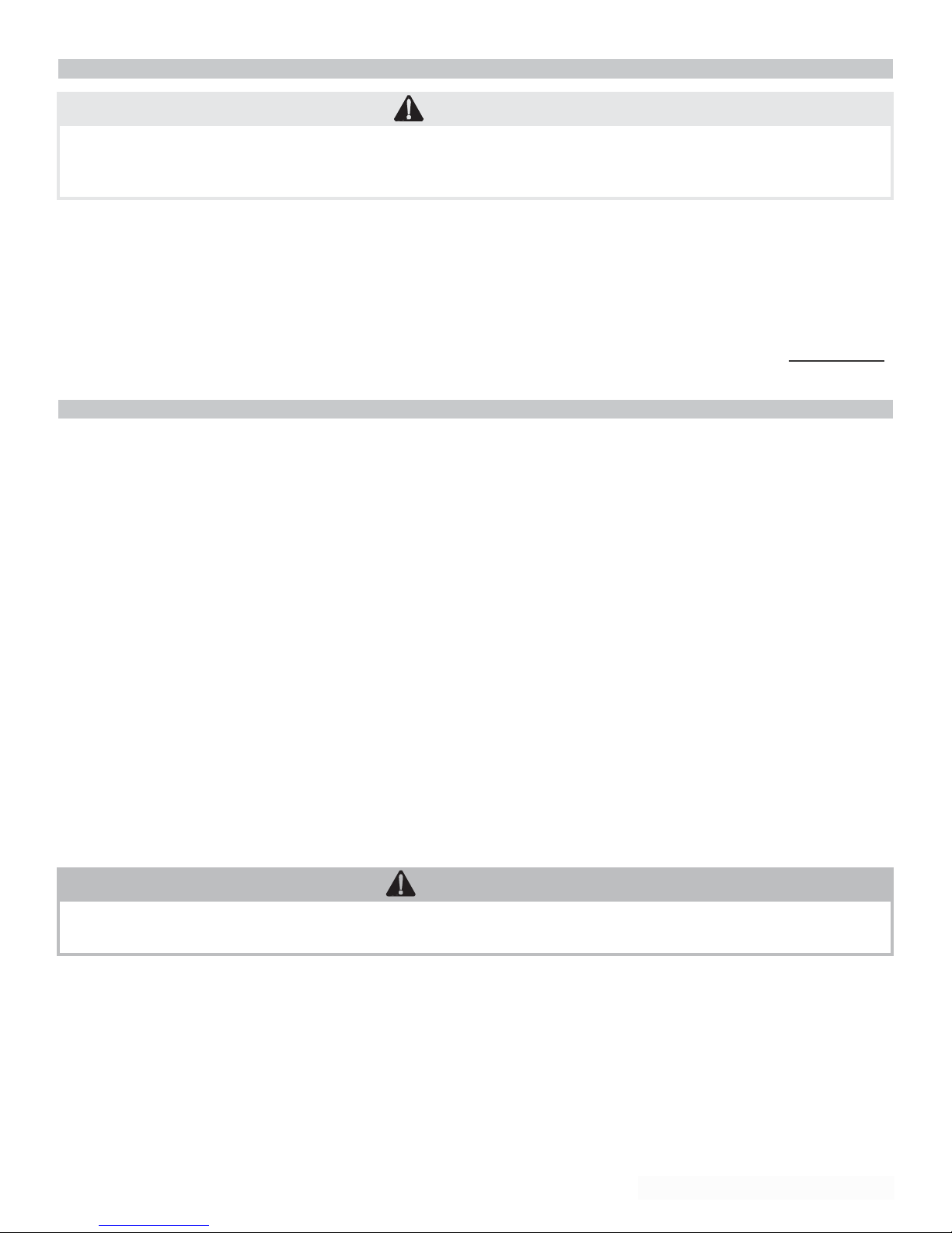
SPECIAL VENTING INSTRUCTIONS FOR 2" VENTED SSV100R, & SSV130R MODELS ONLY.
FOR 3" VENTED MODELS, SEE PAGE 5.
VENTING
SSV100R AND SSV130R ONLY
Inlet air supply, top pipe on the right of the shroud. Use 2" PVC, schedule 40, or 2" ABS for all inlet air piping. It is very important that
you plan the location properly, to eliminate long pipe runs, and excessive fittings. Inlet pipe size must not be reduced. Do not combine
the inlet air with any other inlet pipe including an inlet to an additional similar appliance. The joints must be properly cleaned, primed,
and cemented. The piping must also be properly supported as per local and national standard plumbing codes. It is important that the
piping must be clean and free from burs, debris, ragged ends, and particles of PVC, or ABS. Exhaust piping, lower pipe on right of
shroud, must be of 2" PVC schedule 40 NON FOAM CORE or 2" ABS NON FOAM CORE, 2" CPVC may also be used. 3" PVC, 3"
ABS solid NON FOAM CORE, or 3" CPVC can also be used. Exhaust piping should be sloped back to the connection on the Voyager,
at least 1/4" per foot to remove additional condensate that forms within the pipe. The total combined length of pipe including elbow
allowances (each elbow = 5’ of pipe) should not exceed 85’, both the intake pipe added to the exhaust pipe. The combined vent length
should not be less than a combined length of 6’, plus two 90 degree elbows. Choose your vent termination locations carefully; see
pages 22 and 23. You must place them in a open area, and use the guidelines found on page 20.
VERY IMPORTANT
SSV100R & SSV130R MODELS ONLY!
All venting must be 2", both intake and exhaust.
You may use 3" or 4" venting on both intake and exhaust, to lower the pressure drop, to provide additional venting length. It is impera-
tive when using 3" to follow these instructions very carefully. For longer venting lengths, the first 10’ of both the intake and exhaust pip-
ing are 2". For the intake 10’ of 2" PVC or ABS or CPVC, plus one 90 degree or two 45 degree elbows and for the exhaust 10’ of 2"
PVC NON FOAM CORE or ABS solid NON FOAM CORE or CPVC, plus one 90 degree or two 45 degree elbows. Then use a 2" x 3"
PVC or ABS reducing coupling. Then proceed with ABS solid NON FOAM CORE, CPVC, or PVC 3" NON FOAM CORE pipe and fit-
tings for both the intake and exhaust piping. On 3" piping you may go an additional 125 equivalent feet of pipe and fittings, combined
total length. Total equivalent would be 30’ of 2" plus 125’ of 3". The vent system must be balanced by friction loss equivalent.
CONDENSATE
This is a condensing high efficiency appliance, therefore this unit has a condensate removal system. Condensate is nothing more than
water vapor, derived from the combustion products, similar to an automobile when it is initially started. This condensate does have a
low PH and should be treated with a condensate filter. This filter contains either lime crystals or marble crystals, which will neutralize
the condensate. The outlet of the filter is sized for 5/8" ID (Inside diameter) plastic tubing. It is very important that the condensate line
is sloped away from and down to a suitable inside drain, if the condensate outlet on the Super-E is lower than the drain, you must use
a condensate removal pump. A condensate filter and a condensate pump kit are available from NATCO. It is also very important that
the condensate line is not exposed to freezing temperatures, or any other type of blockage. Plastic tubing should be the only material
used for the condensate line; as steel, brass, copper, or others will be subject to corrosion and deterioration. A second vent may be
necessary to prevent condensate line vacuum lock if a long horizontal run is used. Also an increase to 1" tubing may be necessary,
(See the diagram on page 25).
SSVH MODEL
PERFORMANCE
AND SET-UP INFORMATION
The SSVH models are available in the 90,000 BTU/hr, 130,000, and 199,000 BTU/hr. firing rates. The illustration on back page show
s
the location of the heat exchanger and other ports. For maximum output, the bronze circulator provided must be attached between th
e
hot outlet and cold inlet as shown on page 22. For complete SSVH information and sizing, refer to the back of this manual.
CONTROLDESCRIPTION
The fully integrated water heater control is an all electronic with a fully automatic controller that will provide many years of trouble free
service. The control requires no periodic maintenance and includes a built-in microprocessor which performs a number of diagnostic
tests to verify proper appliance and control operation. Should an unsafe condition occur, the burner will shut down and the appropriate
status indicators will illuminate indicating the need for service. Consisting of two printed circuit board assemblies, the controller’s main
board is attached to inside left of the shroud while the display board is mounted to the front top of the shroud. This arrangement simpli-
fies access to the user adjustments while enhancing the visibility of the temperature display and status indicators. A power step-down
transformer and blower pressure switch are also mounted on the inside left of the shroud. The controller display functions include a
high visibility three digit LED readout which is used to display the actual water temperature within the tank along with the programmed
desired water temperature (set point temperature). Nine individual LED indicators are also mounted on the display board which are
PAGE: 9

used to determine the operating status of the appliance and provide assistance when troubleshooting any problems which may occur.
All indicators are of the solid state variety and should last for the life of the appliance. The controller has sufficient built-in memory to
retain the programmed temperature set point in the event input power is ever interrupted. The final component of the control system
includes a temperature sensing probe which is threaded into the side of the tank. This probe is of unique construction in that both the
temperature sensing/control and safety limit functions are performed by this single device. All probe components are of solid state con-
struction to provide extended operational life.
START UP PROCEDURE
1. Make sure that the Super-E has been installed to these instruction procedures; along with all applicable province and local
codes;
2. Make sure all gas piping and connections have been verified and inspected by all applicable inspectors. Turn on gas supply.
Insure that the gas line and the LP tank, if applicable, have been properly purged. Failure to properly purge the gas lines will
result in failure to operate;
3. Make sure that the cold water supply has been turned on and that the Super-E is completely filled with water. Verify this by
opening a hot water faucet, and allowing water to flow until all air is removed and a clear water flow is present;
4. Turn on electrical supply;
5. The control will first display "102", then "88.8", which is the control display test; and finally the actual tank temperature at the
probe.
SET POINT ADJUSTMENT PROCEDURE
The three digit LED display will illustrate actual water temperature within the tank under normal operating conditions. However, this
display is also used to indicate the temperature set point when in the programming mode; and also ignitor amp draw and flame current.
The controller has a temperature set point range 70 degrees F. to 160 degrees F. The factory set point is 118 degrees F.
D
ANGER
Water temperature over 125 degrees F. can cause severe burns instantly,
or death from scalds. Children, disabled, and elderly are at highest risk
of being scalded.
See
instruction manual before setting temperature at
water heater. Feel water before bathing or showering!
T
e
mperature
limiting valves are available.
VERY IMPORTANT NOTE:
POWER MUST BE APPLIED TO THE CONTROLLER PRIOR TO ANY PROGRAMMING OPERATIONS.
SET POINT ADJUSTMENT
PROCEDURE
(CONTINUED)
To change or access the programmed temperature set point value, utilize the red button on the display panel. Momentarily depressing
the button will briefly illustrate the existing set point value. If the button is held down for more than one second, the programming mode
is entered and the set point value will begin incrementing by one degree per second. When the desired set point value is reached, sim-
ply release the button and the controller will automatically retain this value in temporary memory. After 30 seconds, this new set point
will be retained in permanent memory.
NOTE:
IF POWER IS INTERRUPTED DURING THIS 30 SECOND PERIOD, THE NEW SET POINT WILL NOT BE RETAINED IN PERMA-
NENT MEMORY. IT IS A GOOD PRACTICE TO RE-CHECK THE SET POINT VALUE APPROXIMATELY 60 SECONDS AFTER A
NEW VALUE HAS BEEN RE-ENTERED.
If the button is held down long enough, the set point will reach 160 degrees F. and stop, since this is its maximum value. At this point,
if the desired set point has not been obtained, release the button and depress it again, the set point will decrement down to 70 degrees
F. and stop. The set point value will now restart at 70 degrees F. (its minimum) and once again increase in value for as long as the
button is pressed.
DIFFERENTIAL
ADJUSTMENT PROCEDURE
To allow proper water heater operation, the control has a 8 degree F. "window" around the set point. This means that the burner will
be turned on when the water temperature drops to 4 degrees F. below the set point, and it will be turned off when the water tempera-
ture reaches 4 degrees F above the set point. Thus, if the set point is set to 120 degrees F., the control will turn on the burner when
the water temperature drops to 116 degrees F., and will continue to heat the water until the temperature reaches 124 degrees F. The
differential is factory set to 8 degrees F. (+ or- 4 degrees F.) If another differential is required, the value of the differential can be field
adjusted by holding the set point button when power is applied to the control. Shut off power to the control. Next hold in the set point
button. Now reapply power to the control. Using the set point button, the value of the differential can be incremented or decremented
as above. When the proper value is reached, release the button and the new differential has been stored into permanent memory.
PAGE: 10

O
VERALL
APPLIANCE
AND
CONTROL OPERATION
A normal operating sequence is as follows:
1. The control determines that the actual water temperature inside tank is 4 degrees F., with the factory set 8 degree F.
differential, below programmed temperature set point;
The control performs selected system diagnostic checks;
If all checks are successfully passed, the combustion blower is energized for the 40 second pre-purge cycle;
During the pre-purge cycle is complete, power is applied to the ignitor element for the ignitor warm-up period (blower should
continue to run);
The ignitor warm-up period will last for 30 seconds, then gas valve will be opened, allowing gas to enter the burner chamber;
The ignitor will remain on for an additional 4 seconds, then it will be turned off;
After an additional 2 seconds, the control will verify the presence of flame. If the flame was not established, the gas valve will
be closed, power will be removed from the ignitor element, and the control will run the blower for 30 seconds. At this point,
the control will return to step 2;
If flame is present, the control will enter the heating mode where it will continue heating the tank water until the set point
temperature plus 4 degrees F. is reached. At this point, the gas valve is closed and the control enters the post-purge cycle.
The flame can be viewed through a window on the lower right of combustion blower flange;
The post-purge cycle continues to run the combustion blower for an additional 30 seconds to purge the system of all
combustion gases. After this time period, the blower is de-energized and will coast to a stop;
The control will now enter the idle state while continuing to monitor internal tank water temperature. If the temperature drops
to 4 degrees F. below the set point value, the control will automatically return to step 1.
2.
3.
4.
5.
6.
7.
8.
9.
10.
ST
A
TUS
INDICA
T
ORS
Pages 15, 16, and 17 contain seven individual diagrams which illustrate the various operating states of the appliance and their relation
to the LED status indicators found on the controller. These diagrams reflect normal water heater operation.
MAINTENANCE
The control system requires no periodic maintenance under normal conditions. However, in unusually dirty or dusty conditions, period-
ic vacuuming of the cover to maintain visibility of the display and indicators is recommended. In dirty environments, construction sites,
building constructions, care must be taken to keep the appliance door in place and drywall or saw dust away from appliance.
INTERNAL WIRING
For specific wiring information, please refer to the diagrams on pages 18 and 19.
SHUTDOWN
PROCEDURE
If the burner is operating, lower the set point value to 70 degrees F. and wait for the burner to shut off. Continue to wait for the com-
bustion blower to stop so all latent combustion gases are purged from the system. This should take a maximum of 40 to 90 seconds.
Disconnect the electrical supply. If the burner is not operating, disconnect the electrical supply.
V
ACATION PROCEDURE
If there is danger of freezing, change the set point to 70 degrees F. DO NOT turn off electrical power. If there is no danger of
freezing, follow the "Shutdown Procedure".
F
AIL
URE
T
O
OPERA
TE
Should the burner fail to light, the control will perform two more ignition trials prior to entering a lockout state (“LOC”). Note that each
subsequent ignition trial will not occur immediately. After a failed ignition trial, the blower must run for approximately 10 seconds to
purge the system, then the ignitor element must complete a 30 second warm-up period. Therefore, a time period of approximately 40
to 90 seconds will expire between each ignition trial. If the burner lights during any one of these three ignition trails, normal operation
will resume. If the burner lights, but goes off in about 4 seconds, check the polarity of the wiring. See electrical connection section on
page 4. If the burner does not light after the third ignition trial, the control will enter a lockout state. This lockout state indicates that a
problem exists with either the appliance, the controls, or the gas supply. Under such circumstances, a qualified service technician
should be contacted immediately to properly service the appliance and correct the problem. If a technician is not available, depressing
the red button once will remove the lockout state so additional trials for ignition can be performed. Any time “LOC” is shown, you
must look for an LED out, or flashing. The LED that is out or flashing will assist you in diagnosing lock out condition.
PAGE: 11
C
A
UTION
In unusually dirty or dusty conditions, care must be taken
to keep
appliance door in place. Failure
to
do
so
VOIDS WARRANTY!

PAGE: 1
2

PROPANE/LP GAS CONVERSION FROM NATURAL GAS = .250"
100,000 BTU SUPER-E’S-
AIR ORIFICE = 1.125"
GAS ORIFICE SIZES-
NATURAL GAS = .280" PROPANE/LP GAS = .235"
NATURAL GAS CONVERSION FROM PROPANE/LP = .285"
PROPANE/LP GAS CONVERSION FROM NATURAL GAS = .250"
PAGE: 13
LOW VOLTAGE CABLE ASSEMBLY (710B0041)
INTERCONNECT RIBBON CABLE (7000-665)
LINE CABLE (710B0048)
PUSH BUTTON (7000-667)
TRANSFORMER (7000-666)
GASKET BURNER MOUNTING FLANGE (G5010)
GASKET BLOWER OUTLET FLANGE (G5020)
GASKET AIR INLET (G5030)
GASKET BURNER MOUNTING FLANGE WHITE (7000-815)
ORIFICES
All of the Voyager gas fired water heaters have unique air and gas orifice sizes. Special attention should be paid to these sizes when-
ever converting a heater from one fuel type to another, or when the orifice is changed for any reason. Below is a list of orifice sizes for
conversions to other fuel types and the sizes the voyager was shipped with from the factory. Please note that air orifices do not have
to be changed when switching from one fuel type to another. This information is not intended to allow field conversions by drilling ori-
fices. This is only a guide to correct orifice sizing.
W
ARNING
If
orifices are drilled, the result will be poor ignition,
explosion,
severe bodily injury or death.
All orifices must be obtained through the factory with all necessary labels and the serial number must be provided to the factoryOR
WARRANTY WILL BE VOIDED.
SUPER-E GAS CONVERSION INSTRUCTIONS
FOR CONVERSION OF THE VOYAGER TO PROPANE OR NATURAL GAS. YOU MUST ORDER A CONVERSION KIT FROM THE
FACTORY. BELOW IS A LIST OF THE DIFFERENT MODEL NUMBERS YOU WILL NEED TO REFERENCE WHEN ORDERING
YOUR KIT. PLEASE CALL THE FACTORY AT 1-800-323-9651, CUSTOMER SERVICE TO PLACE YOUR ORDER.
90,000 PROPANE TO NATURAL – (N9AG)
90,000 NATURAL TO PROPANE – (P9A6)
100,000 PROPANE TO NATURAL – (N10AG)
100,000 NATURAL TO PROPANE – (P10AG)
130,000 PROPANE TO NATURAL – (N13AG)
130,000 NATURAL TO PROPANE – (P13AG)
160,000 PROPANE TO NATURAL – (N16AG)
160,000 NATURAL TO PROPANE – (P16AG)
199,000 PROPANE TO NATURAL – (N19AG)
199,000 BTU SUPER-E’S- GAS ORIFICE SIZES-
AIR ORIFICE = 1.375" NATURAL GAS = .379" PROPANE/LP GAS = .295"
160,000 BTU SUPER-E’S- GAS ORIFICE SIZES-
AIR ORIFICE = 1.375" NATURAL GAS = .362" PROPANE/LP GAS = .295"
130,000 BTU SUPER-E’S- GAS ORIFICE SIZES-
AIR ORIFICE = 1.125" NATURAL GAS = .280" PROPANE/LP GAS = .235"
NATURAL GAS CONVERSION FROM PROPANE/LP = .285"
REPLACEMENT
PARTS NOT SHOWN

PAGE: 14
VERY IMPORTANT SET-UP INSTRUCTIONS!
IF YOU HAVE A COMBUSTION ANALYZER, THE FOLLOWING RATINGS WILL BE VERY HELPFUL IN SETTING UP
YOUR SUPER-E:
FOR NATURAL GAS - CO2 READING SHOULD BE BETWEEN 9 ½% & 10 ½%
O2 READING SHOULD BE BETWEEN 3 ½% & 4 ½%
CO READING SHOULD BE UNDER 10 PPM
FOR PROPANE GAS - CO2 READING SHOULD BE BETWEEN 10 ½% & 11 ½%
O2 READING SHOULD BE BETWEEN 3 ½% & 4 ½%
CO READING SHOULD BE UNDER 10 PPM
90,000 BTU SUPER-E’S- GAS ORIFICE SIZES-
AIR ORIFICE = 1.000" NATURAL GAS = .261" PROPANE/LP GAS = .205"
NATURAL GAS CONVERSION FROM PROPANE/LP = .253"
PROPANE/LP GAS CONVERSION FROM NATURAL GAS = .215"
CAUTION:
THERE ARE NO USER SERVICEABLE PARTS WITHIN THE CONTROL SYSTEM. TO MAINTAIN SAFETY AND PROPER APPLI-
ANCE PERFORMANCE, REFER ALL TROUBLE-SHOOTING TO QUALIFIED SERVICE PERSONNEL.
TROUBLE-SHOOTING
The appliance controller has many inherent diagnostic and fault detection routines built into its operating software and hardware.
These routines, along with the three digit LED display and nine LED status indicators present on the display panel, can greatly assist
the service person in quickly pinpointing the source of problems that may occur with the appliance. In certain circumstances, multiple
LED’s may be lit or flashing to better pinpoint the problem. Also, there is a green LED on the main control board to indicate proper
polarity and grounding. The following charts, diagrams, and information can be used during
troubleshooting procedures:
LED CONTROLLER FUNCTION MEANING
LINE MONITORS INCOMING AC LINE VOLTAGE “ON” WHEN LINE VOLTAGE IS PRESENT
BLOWER MONITORS THE BLOWER MOTOR OUTPUT “ON” WHEN OUTPUT IS ENERGIZED
(POWER APPLIED TO BLOWER)
IGNITOR MONITORS IGNITOR ELEMENT OUTPUT “ON” WHEN OUTPUT IS ENERGIZED
(POWER APPLIED TO IGNITOR)
24V MONITORS INCOMING VOLTAGE FROM THE “ON” WHEN SECONDARY VOLTAGE IS PRESENT
TRANSFORMER SECONDARY
ECO MONITORS STATE OF THE ECO SWITCH “ON” WHEN ECO SWITCH AND LOW WATER CUT-OFF
AND LOW WATER CUT-OFF IS IN CLOSED POSITION (NORMAL POSITION)
PRESSURE MONITORS STATE OF THE AIR SWITCH “ON” WHEN THE PRESSURE SWITCH IS CLOSED
(SUFFICIENT COMBUSTION AIRFLOW EXISTS)
GAS VALVE MONITORS THE GAS VALVE OUTPUT “ON” WHEN OUTPUT IS ENERGIZED
(POWER APPLIED TO GAS VALVE)
WATER TEMP. MONITORS WATER TEMP. WITHIN TANK “ON” WHEN TEMP. DROPS BELOW SET POINT
CONTROL MONITORS INTERNAL STATE OF THE “ON” WHEN CONTROLLER FUNCTIONALITY IS O.K.
HEALTH CONTROLLER’S HARDWARE AND SOFTWARE
GREEN ON MONITORS POLARITY AND GROUND CIRCUIT “ON” WHEN GROUND AND POLARITY ARE O.K.
MAIN CONTROL
BOARD

PAGE: 15

PAGE: 16

PAGE: 17

PAGE: 18

PAGE: 19

PAGE: 20
PLEASE NOTE: THE METHODS DESCRIBED ARE SUGGESTED GENERIC METHODS ONLY. SPECIFIC JOB SITE
OBSERVATIONS AND SIZING MAY REQUIRE ALTERNATE INSTALLATION METHODS.
REFER TO FIG. 3A PG. 21 FOR FURTHER DETAILS.
1) Never vent into a walkway or patio area, or any alley, or otherwise public area less than 7’ from the ground.
2) never install a heat saver or similar product to capture waste heat from exhaust.
3) Always have a vent location at least 1’ above maximum snow level.
4) Always have vent 1’ above ground level, away from shrubs and bushes.
5) Always be at least 2’ horizontally from doors or windows. (36” for Canadian installations. Refer to Fig. 3A pg. 21.)
6) Always have vent at least 3’ from inside corner of outside walls.
7) Maintain at least 4’ clearance to electric, bas meters, and exhaust fans or inlets.
8) VERY IMPORTANT!! Inlet air must be taken from outside of building, next to exhaust outlet, no closer than 8”.
9) Always place screens in all the intake and exhaust openings to prevent foreign matter from entering the Voyager.
10) The vent intake and exhaust must be properly cleaned and glued for pressure tight joints.
11) The vent intake and exhaust must be properly cleaned and glued, for pressure tight joints. Several methods for
venting the Super-E can be found on pages 22 and 23. Use the following layout as a guideline; certain site
conditions such as multiple roof lines/pitches may require venting modifications – consult factory. The air inlet must
be a minimum of 1’ vertically above the maximum snow level of 24”, whichever is greater. The air inlet must also be a
minimum of 10’ horizontally from the roof, and terminated with a tee. The exhaust must be minimum of 24” above the
air inlet opening, and terminated with a coupling. It is very important that there are no other vents, chimneys, or air
inlets in any direction for at least 4’. Please refer to typical venting on pages 22 and 23. ALL VENTING MUST BE
PROPERLY SUPPORTED, AS THE VOYAGER IS NOT INTENDED TO SUPPORT ANY VENTING
WHATSOEVER. All piping, glue, solvents, cleaners, fittings, and components, must conform to ASTM (American
Society for Testing and Materials), and ANSI (American National Standard Institute).
12) It is recommended that you use one of the mentioned vent kits specifically for Super-E installations; either
KGAVT0501CVT (2 in.) or KGAVT0601CVT (3 in.) or the V1000.
NOTE: CLEARANCE SHALL BE IN ACCORDANCE WITH LOCAL INSTALLATION CODES AND TH REQUIREMENTS OF
THE GAS SUPPLIER.
C
A
UTION
YOU MUST USE SUPPLIED ABS PIPE FOR FIRST 84” OF EXHAUST PIPING. ADDITIONAL PIPING
CAN BE ABS OR PVC. YOU MUST SUPPORT ALL PIPING, THE APPLIANCE IS NOT INTENDED TO
SUPPORT VENTINGPIPES.
TYPICAL VENTING
This manual suits for next models
1
Table of contents
Other Natco Water Heater manuals
Popular Water Heater manuals by other brands

Giant
Giant UG40-92TFTT-N2U Operation and installation manual

Leda
Leda LCN20 Installation and owner's manual

EHC
EHC NDIR120L Installation and technical manual

Kenmore
Kenmore 153.338071 owner's manual

Rheem
Rheem RUUD Commercial Booster Specifications

Little Giant
Little Giant SS-1.5-42HL Installation and operating instructions