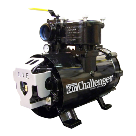
National Vacuum Equipment 607 challenger series Use and care manual

National Vacuum Equipment
MADE
IN USA
Vane Replacement &
Complete Rebuild Manual
607 Challenger Series Rotary Vane Vacuum Pumps

2| 607 Challenger Series www.natvac.com | 800.253.5500
© 2013 National Vacuum Equipment, Inc.
Revision: 5 (Release) March 2013
No part of this manual may be reproduced without the written permission of
National Vacuum Equipment, Inc.

607 Challenger Series | 3www.natvac.com | 800.253.5500
607 Challenger
Owner’s Record
Date of Purchase: _________________________
Purchased from: __________________________
Serial Number: ____________________________

4| 607 Challenger Series www.natvac.com | 800.253.5500
Contents
Introduction 5
General Information���������������������������������������������������������5
Pump Rebuilding
Vane Replacement ����������������������������������������������������������6
Complete Rebuild ����������������������������������������������������������10

607 Challenger Series | 5www.natvac.com | 800.253.5500
Introduction
General Information
About National Vacuum Equipment
Congratulations! You now own a quality vacuum/pressure pump proudly
manufactured in the U�S�A� by National Vacuum Equipment, Inc� You
have not only acquired a superior piece of equipment from a qualied
dealer, you have hired a team of vacuum experts� We stand ready to
work with your dealer to answer your questions and provide you with the
information necessary to keep your equipment in peak working condition�
Thank you for using National Vacuum Equipment�
Our Mission
We are dedicated to the manufacture and wholesale distribution of quality
vacuum system products at a reasonable price, on a timely basis� We are
a “one-stop shop” for manufacturers and distributors of vacuum equip-
ment�
Our History
National Vacuum Equipment, Inc� was founded in 1980 by Bruce Luoma�
The Company started as a retailer of vacuum pumps� Soon after it
started, the Company secured the rights to exclusive distribution of the
Battioni vacuum pumps in North America� This helped the Company to
evolve into its current status as a wholesale supplier�
To reach the goal of becoming a full service supplier of vacuum system
components, the Company began fabrication its own line of componen-
try, purchased and developed its own line of vacuum pumps, and began
purchasing for resale various valves and accessories�
Today, NVE has full service machine, fabrication and powder-coating
shops complete with CNC-controlled production equipment designed for
close tolerance work� The company has a highly trained staff all of whom
are dedicated to quality�

6| 607 Challenger Series www.natvac.com | 800.253.5500
Pump Rebuilding
1� Clean off the exterior of the pump
2� Remove the oil line guard�
Disconnect all oil lines feeding
from the oil pump
Uninstall the oil pump from the
rear bearing cover�
3� Remove the four (4) bolts that
hold the rear bearing cover to
the rear endplate and note that
the wave spring seal is to be
re-used�
607 Fan & Liquid
Vane Replacement

607 Challenger Series | 7www.natvac.com | 800.253.5500
4� Remove the oil pump
drive key from the end of
the rotor�
6� Remove the top two end-
plate bolts and replace
with two (2) 3/8-16 stud/
dowels (or de-headed
bolts), and then remove
the remaining bolts�
5� (Fan Cooled Only)
Remove the fan shroud
supports connecting the
shroud “tin” to the rear
endplate�
7� Remove the rear end-
plate with a gentle
“wiggle”, clean gasket
surface and remove the
vanes for inspection�

8| 607 Challenger Series www.natvac.com | 800.253.5500
8� Inspect the original vanes for
any delamination, chipping or
other damage�
If any of the vanes are worn
more than 1/4”, are chipped
or delaminated they should be
replaced�
We highly recommend replac-
ing vanes in sets� Apply a liberal
amount of lubricant to the vanes
before installing in the rotor
slots�
It is always a good idea to have
a spare set of replacement
vanes on hand to reduce pump
downtime�
9� Install one (1) new endplate
gasket between the housing and
the endplate, do not use any
gasket sealer.
Carefully guide the endplate
onto the rotor and threaded
dowel pins
(Fan Cooled Only) Reinstall the
eleven (11) self-tapping screws
and holding the fan shroud to the
rear end-plate� Fasten the upper
fan shroud tin to the fan shroud
support on the rear endplate�

607 Challenger Series | 9www.natvac.com | 800.253.5500
10� Insert the two (2) “T-handle” pins
provided in your rebuild kit through
the endplate and into the locator
holes at 3 and 6 O’clock positions
on the housing�
Snug the endplate close to the
housing�
(Liquid Cooled Only) The 3/8 hex
bolts located on the water jacket
side of the pump housing need to
have high temperature (Red) RTV
Silicone re-applied�
Install the hex head bolts�
Reseat the outer bearing in the end-
plate pilot�
Tighten the endplate bolts to
35-40 ft-lbs of torque�
At this point you should be able to
turn the rotor by hand�
11� Reinstall the oil pump drive key in the
rotor�
Reinstall the oil pump / rear bearing
cover� Ensure the oil pump shaft is
aligned with the drive key�
Reconnect the oil lines to the oil
pump, and front bearing� Do not
overtighten ttings.
Reconnect the pump to its oil reser-
voir and start at a slow R�P�M�
Run the pump for a few minutes to
allow oil to ll the lines. Inspect the
translucent oil lines to check that oil
is owing.

10 | 607 Challenger Series www.natvac.com | 800.253.5500
Pump Rebuilding
607 Fan & Liquid
1� Clean off the exterior of the pump
2� Remove the oil line guard�
Disconnect all oil lines feeding
from the oil pump
Uninstall the oil pump from the
rear bearing cover�
3� Remove the four (4) bolts that
hold the rear bearing cover to
the rear endplate and remove
the rear bearing cover�
Complete Rebuild

607 Challenger Series | 11www.natvac.com | 800.253.5500
4� Remove the oil pump drive
key from the end of the rotor�
6� Remove the top two (2) bolts
that hold the rear endplate
to the pump housing and
replace with two (2) 3/8-16
threaded dowels� Once in
place, remove the lower six
(6) 3/8 hex bolts�
5� (Fan Cooled Only) Remove
the eleven (11) self-tapping
screws that fasten the fan
shroud “tin” to the pump� Re-
move the fan shroud support
connecting the fan shroud “tin”
to the rear endplate�
7� Remove the rear endplate,
gasket, and vanes�

12 | 607 Challenger Series www.natvac.com | 800.253.5500
8� Place a cushion beneath the
rotor to prevent damage when
the front endplate is unbolted
(cardboard, rag, etc�)�
9� (Fan Cooled Only) Remove the
fan guard on the drive end side
of the pump� Remove the fan
and key from the rotor drive end
by rst loosening the fan hub
screw. You may nd it neces-
sary to drive the hub apart with
a screw driver in order to slide
the fan assembly off of the rotor�
10� Repeat step 6 to drop the rear
end of the rotor down onto the
cushion�
(Fan Cooled Only) Remove
the six (6) hex bolts holding
the aluminum fan shroud to the
front endplate and remove the
shroud�
11� Gently guide the front end-
plate off of the (2) 3/8-16
threaded rod segments to
fully settle the rotor body on
the base of the housing bore�
Remove the rotor with care
from the housing. Place a Tag
on the housing side that corre-
sponds to your drive end side!

607 Challenger Series | 13www.natvac.com | 800.253.5500
12� Remove the four-way
assembly, gaskets, and check
valve assembly� Carefully turn
the housing upside down so
that the pump feet are facing
the ceiling�
13� Inspect the housing for wear or damage� If the housing needs
to be bored or honed, remove only as much material as is
necessary to give a smooth clean bore�
The maximum overbore we recommend is 0�060 inches� A new
housing has a bore of 7�875 inches�
If you bore or hone the housing, remove all connected accessories,
including the fan shroud, 4-way valve, gaskets, etc�
14� Clean the housing of any
debris and apply a liberal
amount of lubrication to the
housing bore�
15� (Optional) If there is damage
evident to the bearings, they
will need to be replaced� Once
the rotor is removed, start
by cutting off the old bearing
inner race on both ends of the
rotor� Be sure to line up the
cutting wheel with one of the
vane slots so as not to dam-
age the rotor or seal sleeve�

14 | 607 Challenger Series www.natvac.com | 800.253.5500
16� Clean the rotor and rotor slots
and inspect the rotor for wear
or damage�
Place the clean rotor inside the
housing with the drive end in the
same orientation it originally was�
This will be the side you tagged in
step 11 of this procedure�
17� (Continuation of Step 15)
Remove the two (2) inner
races from the replacement
bearings provided in your
repair kit�
Place the inner races onto a hot
plate and get them hot� Do not
leave them on the plate so long
that they become discolored�
Use a welding glove to take the
hot inner race from the hot plate
and slide it onto the rotor shaft�
The bearing race shoulder
should be tight against the seal
sleeve�
Install on both sides of the rotor�
Allow ample time for the inner
races to cool and set onto the
rotor before continuing�

607 Challenger Series | 15www.natvac.com | 800.253.5500
19� Shift the housing so that
the intake (Square port) is
hanging slightly off of the
rebuild work surface�
Place one of the 0�007” shims
between the rotor and rotor
bore so that the shim is within
the housing and will not inter-
fere with the endplate when
they are reinstalled�
Divert the pull wire into the
housing cavity and out through
the intake port�
Repeat for both ends of the
rotor�
18� Inspect the original vanes for
any delamination, chipping
or other damage�
A new vane is ush with the
outside diameter of the rotor�
If any of the vanes are worn
more than 1/4”, chipped or
delaminated they should be
replaced�
We highly recommend replac-
ing vanes in sets� Apply a liberal
amount of lubricant to the vanes
before installing in the rotor slots�
It is always a good idea to have
a spare set of replacement
vanes on hand to reduce pump
downtime�

16 | 607 Challenger Series www.natvac.com | 800.253.5500
20� Remove the seals from the
endplates� Inspect for dam-
age, the seals should be soft
and pliable�
Clean the endplate as needed�
Apply new lubricant along the
seal pilot in each of the end-
plates�
The seals need to be installed
back to back� The faces without
the oil groove should be touching�
We recommend using a seal
driver tool to properly seat the
seals in the endplate� Drive the
seals into the endplate�
Repeat for both endplates�
22� Install two (2) 3/8-16 threaded
dowels so that they can sup-
port the weight of the end-
plate for installation�
Install one (1) new endplate gas-
ket between the housing and the
endplate, do not use any gasket
sealer�
Carefully guide the endplate onto
the rotor and threaded rod seg-
ments
21� Lubricate the roller bearing
pilot in the endplate� Using a
bearing driver, seat the roller
bearing into the endplate�
Repeat for both endplates�

607 Challenger Series | 17www.natvac.com | 800.253.5500
23� Insert one (1) of the dowel pin
“T-handles” into either of the
dowel pin holes on the end-
plate through into the housing�
Snug the endplate close to the
housing and install the 3/8 hex
head bolts�
(Liquid Cooled Only) The 3/8 hex
bolts located on the waterjacket
side of the pump housing need to
have high temperature (Red) RTV
Silicone re-applied�
Tighten the endplate bolts to
35-40 ft-lbs of torque�
Repeat the process for the op-
posite endplate, but make sure
to install the “T-handle” dowel pin
on the same side of the hous-
ing as the other endplate, so as
to prevent the rotor from twisting
when the endplates are fully bolted
into place
Rotate the housing right side up
again, so the pump feet are on the
work station�
24� Grasp the shim pull wires
hanging out of the inlet, and
gently pull to remove the
0�007” shims�
You may need to rotate your pump
and pull the wires simultaneously
to get them to release�
25� Reinstall the bearing cover
gaskets, lubricate along the
rotor bearing cover interface,
reinstall the bearing covers
(with wave washers installed)

18 | 607 Challenger Series www.natvac.com | 800.253.5500
27� (Fan Cooled Only) Reinstall
the fan assembly, the key
should be pushed all the way
to the end of the key slot on
the drive end�
Make sure there is sufcient
clearance to mount the fan cover
when positioning the fan assem-
bly� Tighten the fan hub screw�
Refer to step 9 for additional
information�
26� Reinstall the oil pump drive
key in the non-drive end of
the rotor�
Use hardening gasket sealer on
both sides of the oil pump gas-
ket. Apply teon tape to oil pump
bolts�
Install oil pump to the rear bear-
ing cover� Ensure the oil pump
shaft is aligned with the drive key�
Reconnect the oil lines to the oil
pump, and front bearing�
Do not overtighten ttings to the
plastic oil line, or oil ow may be
restricted�

607 Challenger Series | 19www.natvac.com | 800.253.5500
28� Install two (2) four-way
gaskets to the housing
interface�
Reinstall the four way mani-
fold, making sure to line up the
square port on the housing with
the square port on the four way
manifold�
Replace any gaskets / O-rings
as needed�
29� We highly recommend pres-
sure testing your pump for
leaks before putting it to
work� We test our pumps at
20 psi of pressure�
Put a 3” Male NPT plug in the
exhaust port and a similar
adapter that can connect to a
controlled pressurized air supply
in the inlet�
Spraying your pump with soapy
water while pressurized will
expose any bubbling air leaks in
your vacuum pump�
30� Reconnect the pump to its
oil reservoir and start at a
slow R�P�M�
Run the pump for a few min-
utes to allow oil to ll the lines.
Inspect the translucent oil lines
to check that oil is owing.
The pump is now ready to go
to work!

20 | 607 Challenger Series www.natvac.com | 800.253.5500
P.O. Box 685
Traverse City, MI 49685 USA
231.941.0215 Phone | 231.941.2354 Fax
National Vacuum Equipment, Inc.
Other manuals for 607 challenger series
1
Table of contents
Other National Vacuum Equipment Water Pump manuals

National Vacuum Equipment
National Vacuum Equipment 607 challenger series Manual

National Vacuum Equipment
National Vacuum Equipment WPT 480/P Manual

National Vacuum Equipment
National Vacuum Equipment 887 Challenger Series User manual

National Vacuum Equipment
National Vacuum Equipment 607 PRO Challenger Series User manual