Natures Flame EcoChoice PS35 User manual

EcoChoice PS35 Freestanding
Wood Pellet Burning Heater
EcoChoice PS35 Freestanding
Wood Pellet Burning Heater
Installation Specications
Safety testing of the Heatilator PS35
Freestanding Wood Pellet Burning Heater
to AS/NZS 2918:2001 Report 11/2402 & Report 11/2401

2
Installation
Dimensions – EcoChoice PS35 Freestanding
Refer to Safety Test 11/2401 and 11/2402 for all clearances to combustibles.
Installation Clearances & Specications
Minimum clearances shown are in millimetres. The EcoChoice PS35 is tested to AS/NZS2918:2001.
Specications were correct at time of printing but may alter and those detailed below should be used as
a guide only. Refer to the Installation and Operation Manual supplied with every EcoChoice PS35 pellet
re, or if in doubt, consult your Switch Retailer.
External Flue
Location Dimension
(mm)
A 200
B 150
C* 25
D 172
E 75
F 50
G* 75
H 50
I* 53
J* 25
EcoChoice PS35 Pellet Fire
Minimum clearances to combustibles
* from shielded ue
Note: AS/NZS 2918
requires a minimum
of 100mm clearance
for any side requiring
access.
Note: These are
minimum clearances to
combustibles. Actual
installation distances
may be greater.
Internal Flue
B
C
AE
D
G
F
B
F
G
E
B
J
H
A
E
J
J
F
B
IF
E
806mm
514mm
711mm
247mm
527mm
565mm
308mm 223mm
583mm
630mm
Front Side Top

3
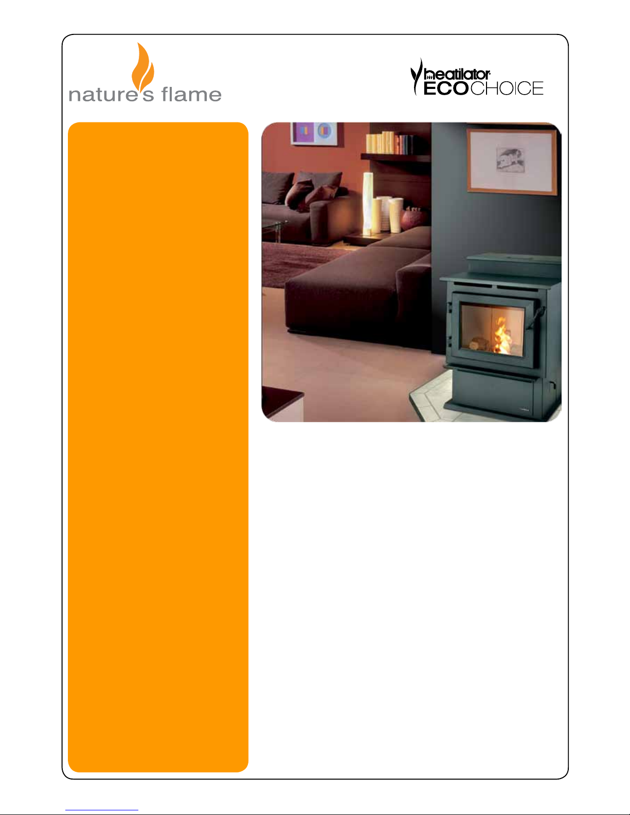
Location of the Pellet Fire
Installation of the EcoChoice PS35 Freestanding Wood Pellet Burning Heater should be
undertaken by an experienced installer. Please read the EcoChoice PS35 Owner’s/Installation
Manual thoroughly before commencing installation as failure to follow the instruction could
cause damage to the pellet re or property.
Positioning the re:
Generally the EcoChoice PS35 should be installed in a centrally located position within the
home. When deciding where to position the appliance in your room you need to consider the
following:
• Location of a power source.
• The EcoChoice PS35 has a convection fan which blows air in the direction that the re
faces, for optimum performance this location should be in a large room centrally located.
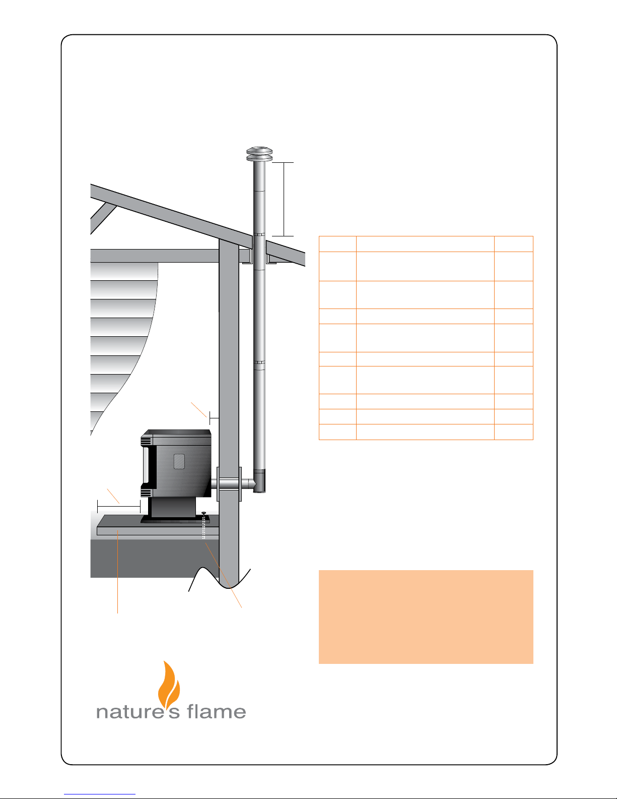
• The EcoChoice PS35 must be installed on a non-combustible surface. This surface
must protrude 150mm from the front of the closed pellet re door.
• The EcoChoice PS35 has been Safety Tested to AS/NZS 2918 using the Davins
manufactured ue. Test Report ARS 05/1185. Installation is not exclusive to these
nominated kits, though alternative ue should only be considered following consultation
with your local council.
• Please consult page 2 for the required clearances to combustible material also ensure
the position of structural elements near the proposed ue.
• Because of the positive pressure in the ue, sealing of all 75mm stainless joints is
mandatory – use high temperature sealant. Both inner and outer ue joints must be
riveted.
• Seismic Restraint: Please view page 6 for requirements.
• Warranty: To validate warranty following installation a copy of the completed Warranty/
Producer’s Statement must be forwarded to: Switch - Fax (03) 341 8057.

4
Internal Standard Flue Kit (50)
Internal Standard Flue Kit
Each 50 Internal Standard Flue Kit contains:-
ytitnauQnoitpircseDoNtraP
1Galvanised outer liner
ø100mm x 900mm long 1
4
3
2
1
1
1
1
1
1
2
2 Stainless steel inner liner
ø75mm x 900mm long
4a Black p/coat outer liner
ø100mm x 900mm long
5Inner/outer ue liner spacer
6c Ceiling thimble ø107mm hole
7c Ceiling decor plate
ø107mm hole – white
8Rain cap 75mm
9Rain Cap 100mm
10b Elbow 45° – ø75mm stainless
–black (painted)
12H T-adaptor/cleanout – ø75mm
–black (painted)
23 Support angle 950mm long
– 50mm x 50mm sides
This ue kit may be used in new and replacement
applications in rooms with stud height of 2.4m. The
overall height of the ue is 3.6m. The visible u e is
nished in black and the ceiling plate is white. T he
support angles for securing the liner to the ceilin g are
not shown. Kit is supplied in a carton.
Heat-resistant
oor protector
Seismic restraint
(to be tted)
25mm minimum clearance if lined ue
600mm from
roof
penetration
172mm
(minimum)
150mm
(minimum)
Note: The Davin 50 Internal Standard Flue
Kit complies with AS/NZS 2918:2001 as per
Applied Research Test Report 05/1185, dated
15 September 2005.
All res must be installed by a qualied
installer as per the manufacturer’s
instructions and AS/NZS2918:2001.
50
To order : Telephone 0800 765 431. Fax 64 3 341 8057 info@switchenergy.co.nzwww.switchenergy.co.nzDecember 2006
Drawing representative only - not to scale.
This ue kit may be used in new and replacement
applications in rooms with stud height of 2.4m.
The overall height of the ue is 3.6m. The visible
ue is nished in black and the ceiling plate is
white. The support angles for securing the liner
to the ceiling are not shown. Kit is supplied in
carton.

5
External Standard Flue Kit (51)
Each 51 External Standard Flue Kit contains:-
ytitnauQnoitpircseDoNtraP
1Galvanised outer liner
ø100mm x 900mm long
2 Stainless steel inner liner
ø75mm x 900mm long
5Inner/outer ue liner spacer
6w Wall thimble – 2 pieces
ø102mm holes
6s Sot thimble ø107mm hole
7w Wall decor plate
ø102mm hole – white
8Rain cap 75mm
9Rain Cap 100mm
26 Lined T-adaptor
This ue kit may be used in new and replacement
applications with the ue penetrating the wall behind
the re, running vertically up an outside wall and
penetrating the sot. The overall height of the f lue is
3.6m. All visible ue has a galvanised nish, and can be
powdercoated on request. Kit is supplied in a carton.
Note: The Davin 51 External Standard Flue
Kit complies with AS/NZS 2918:2001 as per
Applied Research Test Report 05/1185, dated
15 September 2005.
All res must be installed by a qualied
installer as per the manufacturer’s
instructions and AS/NZS2918:2001.
Heat-resistant
oor protector
Seismic restraint
(to be tted)
600mm from
roof penetration
100mm
(minimum)
150mm
(minimum)
External Standard Flue Kit51
4
4
2
1
1
1
1
1
1
To order :December 2006 Telephone 0800 765 431. Fax 64 3 341 8057 info@switchenergy.co.nzwww.switchenergy.co.nz
Drawing representative only - not to scale.
This ue kit may be used in new and replacement
applications with the ue penetrating the wall
behind the re, running vertically up an outside
wall and penetrating the soft. The overall
height of the ue is 3.6m. All visible ue has a
galvanised nish, and can be powdercoated on
request. Kit is supplied in a carton.

6
Flashing Options:
Decktite - For all Steel Roof Proles
Please circle the ashing option to be used. When considering an alternative method please consult
your local council.
SEISMIC RESTRAINT:
All installation scenarios for the EcoChoice PS35 require the use of hold-down anchors (one on each
side)
Fixing to Concrete Floor:
Minimum M8 expansion anchors (M10 recommended) or min M8 epoxy- set anchors.
Approved Anchors: Expansion Anchors-Ramset Dynabolt and Trubolt, Hilti HAS.
Epoxy-set Anchors – Ramset Epcon, Ramset Chemset and Hilti HVU.
Fixing to Timber Floor Framing:
Minimum 14g x 60 screws (6.3mm diameter) or M10mm X 90mm coach-screws. These shall be xed
a minimum of 40mm into the centre-line of the existing oor joists. If screws cannot be installed directly
into an existing oor joist, solid blocking between joists (min size 90x45) shall be provided.
Table of contents
Popular Pellet Stove manuals by other brands

Pelpro
Pelpro PP130 owner's manual

United States Stove Company
United States Stove Company King owner's manual

EdilKamin
EdilKamin VYDA AIR TIGHT Installation, use and maintenance

Quadra-Fire
Quadra-Fire SANTAFE-B1 owner's manual

Erato
Erato Pony PS9 user manual

Buffalo
Buffalo B100 Owner's installation and operation manual