NAUTICAST B2 User manual

PRODUCT MANUAL
Class-B AIS Transponder
Prod.no. 300 1001
Prod.no. 300 1020
Nauticast GmbH
Lützowgasse 12-14 / 3.OG
1140 Vienna, Austria
T: +43 (1) 5 237 237-0
F: +43 (1) 5 237 237-150
office@nauticast.com

DISCLAIMER
Although Nauticast GmbH strives for accuracy in all its publications this material may contain errors or omissions and is
subject to change without prior notice. Nauticast GmbH shall not be made liable for any specific, indirect, incidental or
consequential damages as a result of the usage of this manual. Please visit our website for the latest manual revision at
www.nauticast.com.
COPYRIGHT PROTECTION
This document is protected by copyright law. Copying or duplicating be it physically or electronically for any usage other
than the operation of a Nauticast B2 AIS System is prohibited and any offender may be liable to the payment of damages.
Dieses Dokument ist urheberrechtlich geschützt. Jede Weitergabe oder Vervielfältigung dieser Unterlage ist ausschließlich
zur Unterstützung des Betriebes eines Nauticast B2 AIS Systems zulässig. Zuwiderhandlungen verpflichten zu
Schadenersatz.
Ce document est protégé par le droit d'auteur. Toute redistribution ou reproduction de ce document est autorisée
exclusivement pour appuyer le fonctionnement d'un système AIS B2 Nauticast. Les contrevenants seront passibles de
dommages-intérêts.
Este documento está protegido por derechos de autor. Cualquier redistribución o reproducción de este documento está
permitida exclusivamente para apoyar la operación de un sistema AIS B2 Nauticast. Los infractores quedan obligados por
daños y perjuicios.
GENERAL WARNINGS
An AIS device is a means of communication and relieves the skipper from standard communication for the coordination of
course information with other ships and the traffic control. AIS devices are no navigation devices and do not replace good
seamanship or any other navigational aids such as RADAR. It is the responsibility of the skipper to ensure safe operation
of the ship and to gain knowledge of water, current hazards and other navigation-relevant information.
The function of AIS equipment may be affected by internal and external influences or by defects. Influencing factors are,
for example, electromagnetic environment, interference from other radio emissions, weather, "visibility" and availability of
satellites of the positioning system, physical obstacles to VHF propagation or the quality of the device and in particular the
antenna installation. It is therefore necessary to regularly check the functioning of the AIS and the quality of the data
output by the AIS.
The compass safe distance of this unit is 0.55m or greater for 0.3° deviation.
Every AIS device needs to be registered with the competent authority for radio communication. In most countries the
operation of an AIS unit is included under the vessel’s marine VHF license provisions. The vessel onto which the AIS unit
is to be installed must therefore possess a valid VHF radiotelephone license which lists the AIS system and the vessel Call
Sign and MMSI (Maritime Mobile Service Identity) number. Please contact the relevant authority in your country for more
information.
NOTE FOR OPERATION IN THE USA
In the United States the MMSI and static data may only be entered by an authorized dealer; the end user of the equipment
is not authorised to enter or change their own vessel data.
If your AIS transceiver has not been pre-configured please contact your dealer for details of how to have it configured.
LIMITED WARRANTY
This product is warranted against factory defect in material and workmanship for a period of 24 months from the date of
purchase. During the warranty period Nauticast GmbH will repair or at its option, replace the product at no cost to the
buyer. In any warranty case please contact your dealer or Nauticast GmbH, Lützowgasse 12-14 / 3. OG, 1140 Vienna,
Austria (see Contact & Support information). This warranty does not apply if the defect is caused by mechanical or electrical
forces beyond the specifications in this manual or as a result of service or modification by unauthorized personnel. For
authorized service partners see our homepage www.nauticast.com or contact Nauticast support directly.
Warranty and certification void if device is opened.
© 2019 Nauticast GmbH
Nauticast is a protected trademark of Nauticast GmbH

Page 3 of 32
B2 Product Manual 2.6
Index
1WHAT IS AIS? ..................................................................................................................................................... 5
1.1 THE AIS STANDARD ........................................................................................................................................ 5
1.2 THE "AIS FAMILY".......................................................................................................................................... 5
1.2.1 Class A........................................................................................................................................................... 5
1.2.2 Inland AIS ...................................................................................................................................................... 6
1.2.3 Class B ........................................................................................................................................................... 6
1.2.4 AIS Base Station ............................................................................................................................................ 6
1.2.5 AIS AtoN (Aids to Navigation) Stations ......................................................................................................... 6
1.2.6 AIS SAR (Search and Rescue Aircraft)............................................................................................................ 6
1.2.7 AIS SART (Search and Rescue Transmitter) ................................................................................................... 6
1.2.8 AIS EPIRB (Emergency Position Indicating Radio Beacon) and AIS PLB (Personal Locator Beacon).............. 6
1.3 INFORMATION TRANSMITTED BY AIS TRANSPONDER............................................................................................... 6
1.4 TRANSMISSION INTERVALS................................................................................................................................ 6
2INSTALLATION.................................................................................................................................................... 7
2.1 CONTENTS OF THE NAUTICAST B2 SET (P/N:300 1001)......................................................................................... 7
2.2 SOFTWARE PREREQUISITES ............................................................................................................................... 7
2.3 INSTALLING THE LINK2AIS SOFTWARE ONTO YOUR PC ............................................................................................ 7
2.4 ENTER YOUR SHIP’S DATA ................................................................................................................................. 7
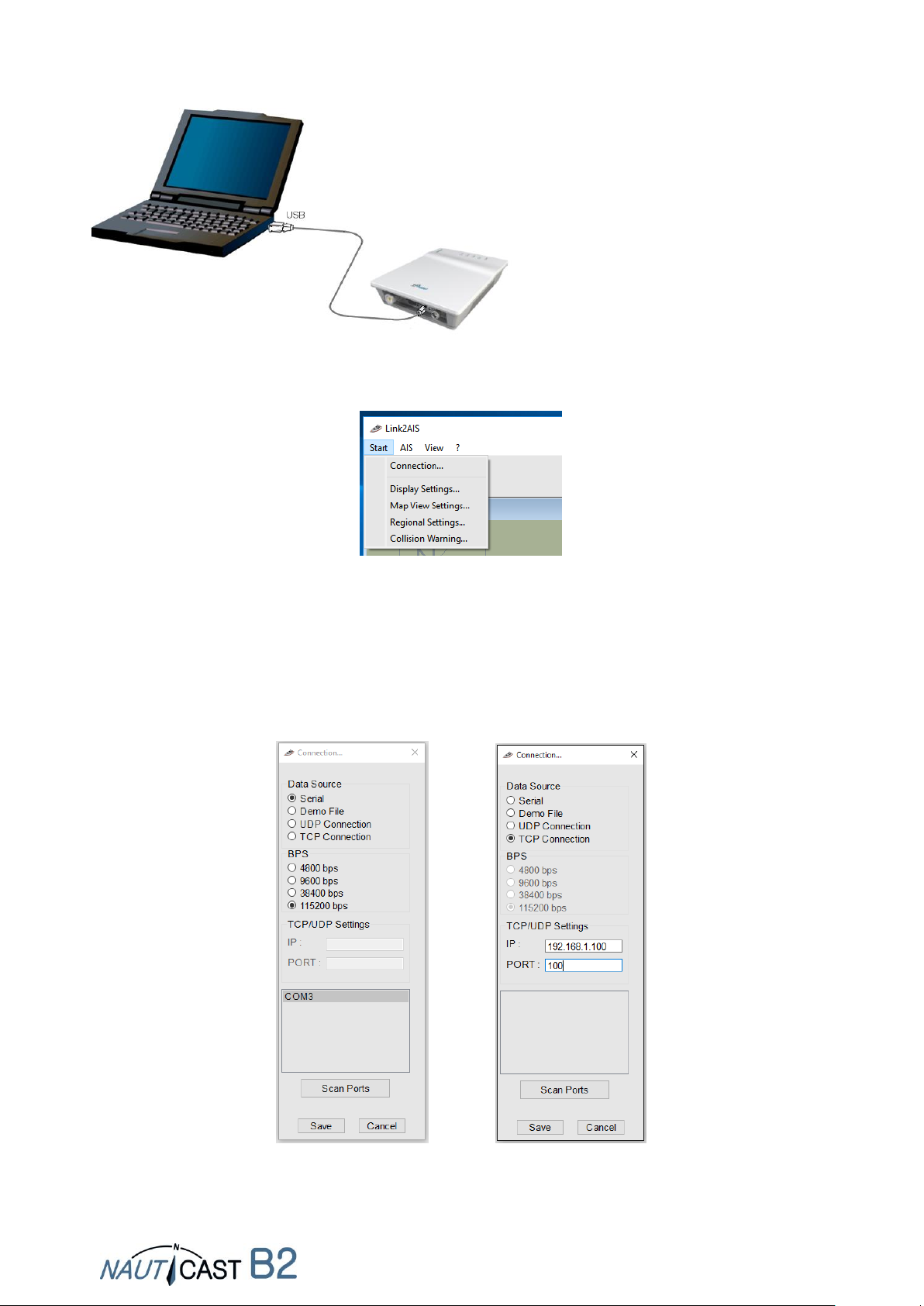
2.4.1 Connecting the Nauticast B2 to your PC ....................................................................................................... 7
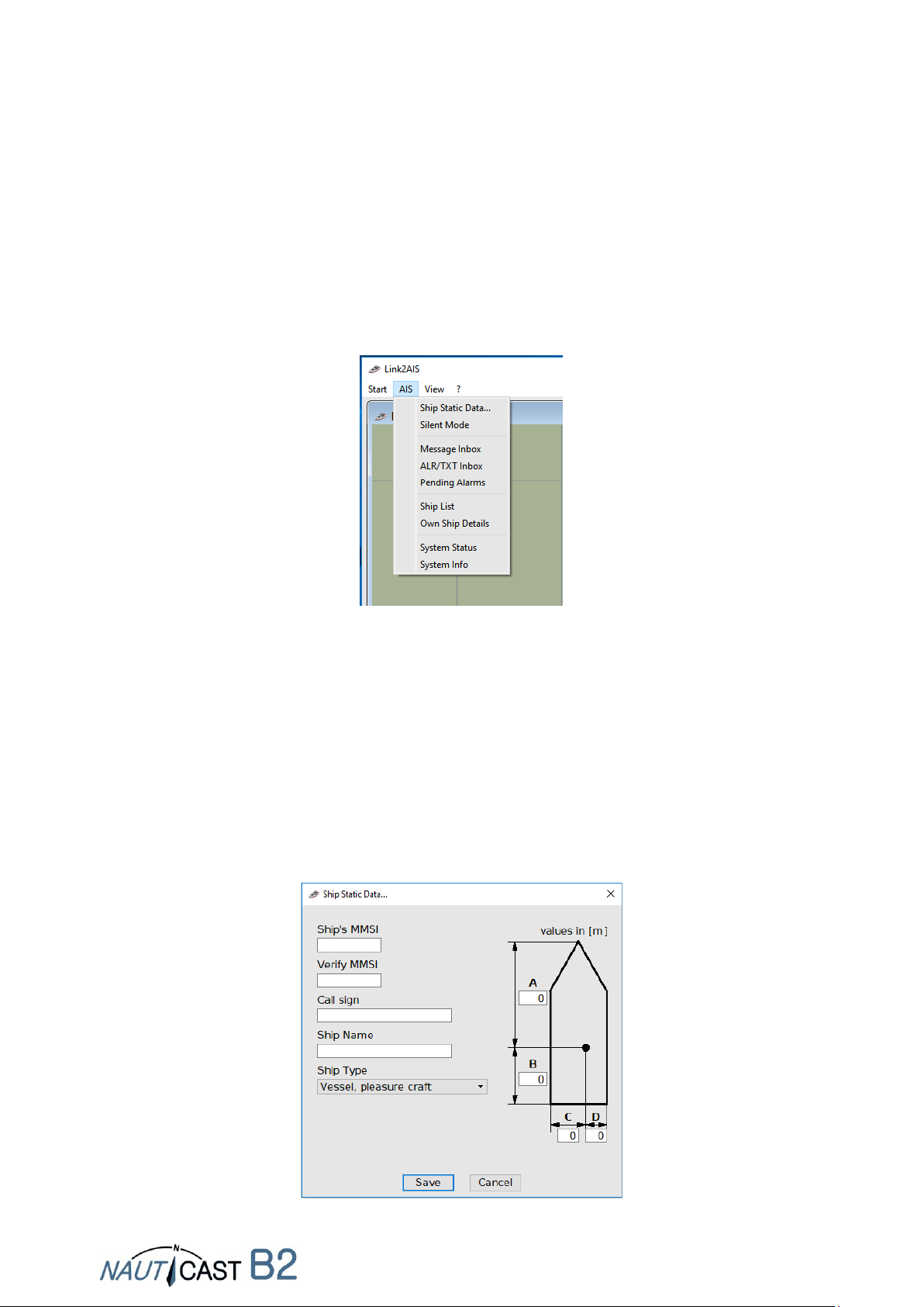
2.4.2 Configuring Software and Nauticast B2 static data...................................................................................... 9
2.4.3 Transferring and saving static data to the Nauticast B2 ............................................................................ 10
2.5 INSTALLING YOUR NAUTICAST B2 HARDWARE ON THE VESSEL ..................................................................................11
2.5.1 Installation hints ......................................................................................................................................... 11
2.5.2 Warnings..................................................................................................................................................... 11
2.5.3 Mounting the Nauticast B2......................................................................................................................... 12
2.5.4 Connecting the antennas ............................................................................................................................ 12
2.5.5 Connecting Power ....................................................................................................................................... 12
2.5.6 Installation Check........................................................................................................................................ 12
3CONNECTING EXTERNAL EQUIPMENT ...............................................................................................................13
3.1 CONNECTING TO A PC.....................................................................................................................................13
3.2 CONNECTING TO OTHER MARINE EQUIPMENT VIA NMEA0183................................................................................13
3.3 ALARM OUTPUT /CONNECTING AN ALARM RELAY ................................................................................................13
3.4 SILENT MODE................................................................................................................................................14
3.5 EXTERNAL LED STATUS INDICATORS (OPTIONAL DATA CABLE P/N 300 1004 REQUIRED)................................................15
3.6 USING DIFFERENT ANTENNAS............................................................................................................................15
3.6.1 GPS Antenna ............................................................................................................................................... 15
3.6.2 VHF Antenna ............................................................................................................................................... 15
4OPERATION OF YOUR NAUTICAST B2................................................................................................................17
4.1 NOTE..........................................................................................................................................................17
4.2 INTERPRETING STATUS LEDS............................................................................................................................17
4.2.1 PWR............................................................................................................................................................. 17
4.2.2 TX (Timeout)................................................................................................................................................ 17
4.2.3 ERR - Error ................................................................................................................................................... 18
4.2.4 CH1 and CH2 –channel information........................................................................................................... 18
4.3 DATA PORT MESSAGES (NMEA 0183) .............................................................................................................18
4.4 STANDARDS .................................................................................................................................................18

Page 4 of 32
B2 Product Manual 2.6
5MAINTENANCE AND TROUBLESHOOTING .........................................................................................................19
6CONTACT & SUPPORT INFORMATION ...............................................................................................................19
7TECHNICAL DETAILS...........................................................................................................................................20
7.1 PRODUCT SPECIFICATION.................................................................................................................................20
8APPENDIX..........................................................................................................................................................21
8.1 APPENDIX A–BLOCK DIAGRAM ....................................................................................................................21
8.2 APPENDIX B–PIN LAYOUT /CABLE CONNECTIONS ............................................................................................22
8.3 APPENDIX C–DIMENSIONS NAUTICAST B2......................................................................................................23
8.4 APPENDIX D–GPS ANTENNA.......................................................................................................................24
8.5 APPENDIX E–VHF ANTENNA .......................................................................................................................25
8.6 APPENDIX F–DECLARATION OF CONFORMITY...................................................................................................26
8.7 APPENDIX G–BSH CLASS BTYPE APPROVAL ...................................................................................................27
8.8 APPENDIX H–FCC CLASS BTYPE APPROVAL....................................................................................................28
8.9 APPENDIX I–DIAGNOSTICS AND TROUBLESHOOTING..........................................................................................29
History of Changes in this Product Manual
Software/firmware dependencies
This revision of the manual is valid for the latest software/firmware versions listed below.
Date
Version
Status
Comments
2018-01-31
2.5
Release
Adaptations to Link2AIS 4.0
2019-02-28
2.6
Release
Communication test
Date
B2 Firmware
Status
Comments
2017-10-31
FW3033-010
Release
Improvements for firmware update
2018-06-27
FW3033-12
Release
Communication test, internal
optimizations for transmission behaviour
Date
Link2AIS
Status
Comments
2017-10-31
4.0
Released
New menu structure, Silent Mode Switch,
collission warning
2018-05-16
4.1
Release
Status bar, Communication test
2018-09-07
4.2
Release
Update for Link2AIS, guided
troubleshooting, vessel types added,
display corrections for HR Screens and
Windows scaling

Page 5 of 32
B2 Product Manual 2.6
1WHAT IS AIS?
1.1 The AIS Standard
AIS stands for "Automatic Identification System". AIS-devices permanently send and receive
standardized digital messages with significant ship information such as vessel name, MMSI, callsign
and navigational data on two exclusively reserved channels of the marine radio band (channel 87B
161.975 MHz and channel 88B 162.025 MHz). This allows vessels to be identified without eye contact
and their position to be located (eg. at night, in bad weather, at blind spots of the radar or at a great
distance). AIS devices thereby increase the safety of the navigation and contribute to the avoidance
of collisions. For the participation in the AIS network technically only a corresponding AIS device is
necessary.
AIS is a worldwide standard based essentially on 2 pillars:
•International Telecommunication Union (ITU) radio standard: currently ITU-R M.1371-5 and
M.825-3 and M. 1084-5.
•AIS International Maritime Organization (IMO) Standards of Operation: IMO Resolution
MSC.74 (69) Annex 3
AIS devices are part of the Global Maritime Distress and Safety System (GMDSS).
1.2 The "AIS family"
The AIS standard is not only supported by devices on ships, but increasingly also on land by base
stations, on marine and river infrastructure such as buoys, offshore platforms, on aircraft in the
framework of sea rescue operations and as a personal safety device.
The following exhibit illustrates a typical AIS network in which multiple AIS-equipped ships and
systems communicate with each other on land and in the air.
1.2.1 Class A
Class A devices comply with the highest AIS standards and are typically installed on all major vessels
(carriage requirement for vessels above 300 gross tons since 2004). On large vessels AIS targets, ie
other ships, are visualized on very large electronic chart systems (ECDIS). This ensures that even
small ships are visible when sending out AIS messages. Class A devices transmit at 12.5W and take
precedence over Class B devices in overcrowded regions when transmitting.

Page 6 of 32
B2 Product Manual 2.6
1.2.2 Inland AIS
AIS is not only used at sea but also on inland waterways. There are minimal differences to the
class A standard.
1.2.3 Class B
Class B devices are simplified devices for recreational shipping and transmit with 2W transmission
power. With a good antenna installation and generally favorable conditions this allows for up to
15 km range.
1.2.4 AIS Base Station
AIS base stations of naval authorities serve to monitor and control shipping. Base stations can also
control the functions of AIS devices (eg. broadcasting intervals).
1.2.5 AIS AtoN (Aids to Navigation) Stations
AtoNs mark facilities such as buoys, platforms, wind farms and provide navigation support. AtoNs
can also transmit (encrypted) individual messages, for example, to forward sensor information.
1.2.6 AIS SAR (Search and Rescue Aircraft)
AIS for helicopters and aircraft participating in Maritime Search and Rescue operations.
1.2.7 AIS SART (Search and Rescue Transmitter)
Is in a lifeboat or on a life jacket and sends AIS position signals in an emergency. These are received
by AIS-equipped ships within a radius of up to 10km and can facilitate the search operation. SART
do not trigger a distress alert (GMDSS emergency procedure).
1.2.8 AIS EPIRB (Emergency Position Indicating Radio Beacon) and AIS PLB (Personal Locator
Beacon)
EPIRBs and PLBs are functionally very similar devices that issue a distress alert (GMDSS emergency
procedure) with position notice. EPIRBs are associated with a boat, PLBs with a person. Traditionally,
satellite signals have been sent. Now additionally or exclusively AIS signals are sent out.
1.3 Information transmitted by AIS transponder
The following table contains data sent by Class A devices. Information sent by Class B is in blue
and bold print:
• Vessel Name
• Vessel Dimensions
• Status
• MMSI Number
• Vessel Type
• Draught
• Position
• Rate of Turn (ROT)
• ETA
• Speed (SOG)
• Navigational Status
• True Heading
• Call Sign
• IMO Number
• Cargo
• Course (COG)
• Destination
1.4 Transmission Intervals
AIS devices send different messages with different standardized content. For example, static ship
data such as the ship's name will only be sent out every 6 minutes independent from the position
report (same for class A and class B). Dynamic data such as speed and course over ground are
transmitted by Class A equipment at intervals of 2 sec (speed> 23 knots) up to 3 min (ship at
anchor), and in class B equipment at intervals of 5 sec to 3 min.
The Nauticast B2 transmits position reports (Message 18) at intervals of
• 30 seconds: when sailing (SOG)> 2kn;
• 3 minutes when sailing (SOG) <2kn
The transmission intervals can be controlled by base stations and also depend on the availability of
time slots in the transmission area.

Page 7 of 32
B2 Product Manual 2.6
2Installation
2.1 Contents of the Nauticast B2 Set (p/n: 300 1001)
(*: contents of Nauticast B2 device (p/n: 300 1020)
Before proceeding with the installation of the Nauticast B2 please check the contents of the box,
which includes:
•The Nauticast B2 AIS transponder (p/n: 300 1010) *
•Mounting plate *
•Power Cable *
•USB Cable *
•VHF Antenna with connection cable and mount
•GPS Antenna with connection cable and mount
•Data Cable for NMEA0183 (p/n: 300 1012) *
•Printed manual (English, 32 pages) *
•USB data card with documatation and software:
oNauticast B2 Product Manual (EN, DE, ES, FR, NL, PL)
oNauticast B2 Product Sheet
oLink2AIS Setup
oLink2AIS User Guide
The installation should be completed in 3 separate steps. Complete each step before proceeding to
the next:
1. Install the Link2AIS software onto your PC (Windows).
2. Enter your ship’s data (MMSI, Vessel Name, Call sign, Length, Beam, ship type) into the
Link2AIS software and save them onto the Nauticast B2 (only USB connection necessary).
Install your Nauticast B2 hardware on your vessel.
2.2 Software Prerequisites
The Link2AIS-software is designed to operate with Microsoft Windows operating systems. The
recommended minimum system requirements are:
•Microsoft Windows 7, 8, 8.1 or 10
•Recommended screen resolution of 1280 x 1024 (although the Link2AIS-software can
operate on screens with smaller resolution, with the use of scroll bars).
•One free USB port –minimum USB 2.0.
•A pointing device (mouse or equivalent).
•An Internet Browser used for the help system.
2.3 Installing the Link2AIS software onto your PC
The Link2AIS-software is in the ‘software’ folder of the USB data card or may be downloaded from
the homepage of Nauticast GmbH (https://www.nauticast.com/en/cms/downloads). Unzip the
package when necessary, double click on ‘setup.exe’ to start the installation process. Follow the
screen prompts to install the Link2AIS software.
A Start Menu folder and a shortcut on your desktop will be created with the name 'Link2AIS'. This
short cut should be used to launch the application.
2.4 Enter your ship’s data
2.4.1 Connecting the Nauticast B2 to your PC
Connect the Nauticast B2 to your PC/notebook where Link2AIS is installed. We recommend using
the USB connection as then no other external power source is necessary for the Nauticast B2. If you
use the data cable (p/n 300 1012 or 300 1004) for connecting, the Nauticast B2 needs to be
connected to a 12VDC or 24 VDC power source and and the serial connection established after that.
Make sure the device is recognized correctly by your PC (Windows shows a message on the task
panel what COM port has been assigned).
Alternatively the connection for programming the Nauticast B2 may also be established via the
Nauticast W1 Serial to Wifi server (TCP protocol).

Page 8 of 32
B2 Product Manual 2.6
•Start the Link2AIS software program on the PC.
•Open the connection settings: Start - Connection
•By pressing ‘Scan Ports’ the software checks the available ports for the device and gives
you a suggestion when an AIS device is found. The serial port (port number can be found
in the device manager of Windows) can also be selected manually from the menu. Click
'Save' when the right port is selected. For the Nauticast B2 115200 bps need to be used.
•If you are using the Nauticast W1 for programming the Nauticast B2, please use
analoguos settings as in the exhibit below. Detailled instructions can be found in the
Product Manual of the Nauticast W1.

Page 9 of 32
B2 Product Manual 2.6
2.4.2 Configuring Software and Nauticast B2 static data
•Once a connection is established, you can start programming static data into the
Nauticast B2. Any error messages shown during USB-only connection can be ignored
(such as send and receive errors, position errors etc.). There is a context based Help
available. The help system is started by pressing the F1 key on your PC or via the menu
‘? – Link2AIS Help’.
•The functions of Link2AIS are arranged in several menus. The menu will adapt
dynamically to the the connection status and device type connected. Hence not all menu
entries shown below may be visible.
•Open ‘AIS – Ship Static Data’. This will display the 'Static Data' for the connected
Nauticast B2. This includes the vessel's name, call sign, MMSI number and other fixed
information. For a Nauticast B2 in factory settings, the fields will be empty.
Enter all vessel information in the appropriate fields:
•MMSI number - enter the vessel's Maritime Mobile Service Identity number (see warning
and further notes regarding MMSI below!)
•Repeat input of the MMSI to prevent typos
•Call Sign - enter the vessel's radio call sign (7 characters minimum)
•Ship name - enter the name of the vessel (20 characters maximum)
•Select the appropriate vessel type from the drop down menu.
•Enter the vessel’s dimensions as follows, rounded to the nearest meter:
oDimension A - distance from GPS antenna location to bow
oDimension B - distance from GPS antenna location to stern
oDimension C - distance from GPS antenna location to port
oDimension D - distance from GPS antenna to starboard

Page 10 of 32
B2 Product Manual 2.6
2.4.3 Transferring and saving static data to the Nauticast B2
CAUTION:
For security reasons the MMSI cannot be changed by the end user once they are
programmed. Please check the number entered carefully. You can change all other static
data (except the MMSI) at any time by running Link2AIS, should the need arise. If the
MMSI is programmed incorrectly or has to be changed lateron date you have to contact
your Nauticast dealer or Nauticast GmbH (www.nauticast.com) for a MMSI reset.
When you have entered all of the vessel's data click the 'Save' button to program this configuration
into the AIS transponder. A warning will be displayed asking you to verify the MMSI number. Please
check the MMSI.
•if the MMSI is not correct, click the 'No' button to cancel programming of the MMSI.
•Click the 'Yes' button if the MMSI is correct.
The ‘Identification’ window will refresh and show the current vessel information stored in the device.
The MMSI number will be displayed with a grey background, to indicate that it has been programmed
and cannot be changed.
You can now disconnect the device from the USB cable / PC and install the hardware on your vessel.
A PC is not necessary for normal operation but can be useful to display AIS data, maps and system
status.
For additional information about the Link2AIS software please refer to the Link2AIS Software User
Guide (‘Help –Link2AIS-Help’, section Documentation).

Page 11 of 32
B2 Product Manual 2.6
2.5 Installing your Nauticast B2 hardware on the vessel
2.5.1 Installation hints
•The GPS antenna needs a free view to the sky through 360 degrees with a vertical angle of
5 to 90 degrees above the horizon and free of shadow effects from the ship’s rig or other
super-structure. Avoid mounting in strongly fluctuating places, such as at the top of the mast.
GPS reception may be affected by DC motors, coils and other electrical equipment. Make
sure that the GPS antenna is as far away as possible from Radar, Inmarsat and Iridium
antennas and is not located directly in their transmission beam. Keep a minimum distance of
2m to MF / HF and other VHF transmitting antennas.
•The decisive criterion for a good signal range is a high and free-standing position of the VHF
antenna. Make sure that the VHF antenna is as far away as possible from radar, Inmarsat
and Iridium antennas and is not located directly in their transmission beam. Maintain a
minimum distance of 2m (ideally vertically offset) to MF / HF and other VHF transmit
antennas and also people's permanent location.
•The supplied VHF antenna can be shared with other VHF transmitters / receivers using a
VHF-splitter. The splitter must be suitable for use with an AIS transponder (receive and
transmit). A splitter for an AIS receiver is not suitable.
•The Nauticast B2 transponder should be mounted on a vertical bulkhead or surface with the
connectors / cables in the downward position. Use the provided mounting plate. The
mounting location must be protected from weather (e.g. rain, snow, ..) and direct water
spray. The best place, therefore, is at the navigation desk, under the helm station or some
other suitable location in the cabin. Keep a safe distance to other electronic equipment of at
least 0.55m.
•The cables (GPS, VHF, power and data) need to be secured to the bulkhead within 6” to 12”
(15 to 30cm) from the connectors. Run cables in cable ducts, avoiding strains, sharp bends
or edges and kinks in the cables. Do not route cables through very hot areas, near motors,
other electrical equipment, or electromagnetically radiating components.
2.5.2 Warnings
•We recommend using the parts and cables provided with the Nauticast B2 to connect
antennas, power and display devices in order to ensure the proper functioning of the system.
•Do not connect the Nauticast B2 unit to a main line 110/220V AC electrical supply as this
could cause electric shock or fire. Only use 12-24V DC power sources!
•Do not connect the Nauticast B2 unit to a DC supply exceeding 24V DC and mind the supply
polarity.
•The length of either data or power cable must not exceed 3 meters.
•Do not apply excessive force to connectors during installation!
•The Nauticast B2 unit is designed for operation in the temperature range -15 °C to +55 °C.
Do not install (or use) the Nauticast B2 unit in environments which exceed this range.
•Connecting a mismatched or defect VHF antenna, leaving the VHF antenna port disconnected
or shorting the VHF antenna socket, will prevent the unit from properly sending position
reports and may cause damage to the transponder.

Page 12 of 32
B2 Product Manual 2.6
2.5.3 Mounting the Nauticast B2
Attach the mounting plate with Phillips self tapping head screws (10-32 x 1,2) on a vertical surface.
Please see Appendix C for the mounting plate’s exact dimensions.
Then insert the Nauticast B2 main unit and press down firmly until it snaps in.
2.5.4 Connecting the antennas
Connect the down-lead cable from the VHF antenna to the VHF antenna socket and connect the
down-lead cable of the GPS antenna to the GPS antenna socket. Please see 8.1 APPENDIX A –Block
Diagram for proper antenna installation.
2.5.5 Connecting Power
Connect the power cable to a 12 VDC or 24 VDC power supply, capable of supplying 2A peak to the
DC power lead (red = positive, black = negative) ). Make sure the power supply is stable and
protected by fuses or circuit breakers. If the DC power source is shared with multiple loads, make
sure 2A is available for the Nauticast B2. Then plug the power connector into the Nauticast B2.
Please see 8.2 APPENDIX B –Pin Layout / Cable Connections of this manual for details of the power,
data and RF cables supplied.
2.5.6 Installation Check
You now have successfully completed the installation of your Nauticast B2 AIS system. After
connecting the main power supply allow the system 5 minutes to calibrate and start operation.
Then check the LED status. Normal operation is indicated by:
PWR: green (Note: LED will be a dimmer shade of green on USB power supply as well,
however, USB-only power supply is NOT sufficient for full operation, so make sure
12-24VDC main power is actually supplied!)
TX: off
ERR: off
CH1, CH2: blinking green, amber or red (when actual transmissions occur, dark in between
transmissions)
When you encounter a different behaviour please consult section 4 Operation of your Nauticast B2.
2.5.7 Communication test
By right-clicking on a vessel in the ship list, an autonomous test of 2-way transmission with the other
device can be performed. The test does not require oiperator intervention. We recommend a
distance of the other vessel of approx.. 3 to 5 km.

Page 13 of 32
B2 Product Manual 2.6
3Connecting external equipment
External equipment can be any device complying with NMEA0183 standard or a PC with appropriate
AIS software installed. For information about the data see section 4.3 “Data Port Messages (NMEA
0183)”. Please note that a USB connection disables the serial interfaces (RS232 and RS422),
therefore they can’t be used simultaniously. However the RS232 and the RS422 interfaces and all
other ports of the data cable will communicate at the same time.
3.1 Connecting to a PC
The connection to a PC can be established either via USB (provides a Virtual Serial Interface) or with
the Data Cable (p/n 300 1012 or optional p/n 300 1004) and a serial interface (RS232), if the latter
is available on the PC. Alternatively data can be broadcast via Wifi by connecting to a Nauticast W1
Serial to Wifi Server.
3.2 Connecting to other marine equipment via NMEA0183
All other devices that support the NMEA0183 standard can be connected with Cable 1 (RS422) or
Cable 2 (RS232) of the Data Cable (p/n 300 1012 or optional p/n 300 1004). (see 8.2 Appendix B
for more details).
Data cable 300 1004 / 300 1012
On connecting your Nauticast B2 to a chart plotter, please check the details for the settings in your
chart plotter manual. Each chart plotter behaves slightly differently.
Furthermore make sure you choose the correct NMEA channel as most devices have several input
channels. The Baud rate for the channel must be set to 38400 when using the RS422 interface and
115200 when using the RS232 interface.
In the table for cable 1 of the data cable below you can find the wire connections for a chart plotter
or any other attached NMEA compatible device.
CABLE 1 (RS422):
Connect the appropriate cable ends to the designated NMEA 0183 device (Baud rate 38400).
Wire end Nauticast B2
end of attached NMEA device
RS422 TX B (+), yellow (Output)
connect to
RX B (+)(Input)
RS422 TX A (-), green (Output)
connect to
RX A (-)(Input)
RS422 RX B (+), white (Input)
connect to
TX B (+) (Output)
RS422 RX A (-), grey (Input)
connect to
TX A (-) (Output)
CABLE 2 (RS232):
Connect the D-SUB 9-pin connector to a matching RS232 serial interface. This connection uses a
Baud rate of 115200 by default.
3.3 Alarm Output / Connecting an alarm relay
There are 2 ways to signal an alarm output from Cable 3 of the Data Cable:
•LED visualisation
•Connected alarm relay

Page 14 of 32
B2 Product Manual 2.6
LED visualisation:
If you want to signal an alarm with a LED only, you can connect the LED with a series resistor R
between + (grey) and ALARM OUT (yellow). Depending on the Voltage used for the Nauticast B2
you either have to use a 470 (calculated 500) resistor (LED: UF=2V, IF=20mA) when using 12VDC
or a 1k(calculated 1100) when using 24VDC.
How to connect a LED to Alarm OUT (cable 3)
Alarm Relay:
The optional alarm relay (p/n 300 1009) needs to be connected to the yellow and grey wires of
cable 3 of the data cable. The input voltage of the alarm relay is matched to the operating voltage
of the Nauticast B2. The operating voltage of the alarm relay is 3 to 60 VDC with a load current of
0.1 to 2A (3A when using a heat sink).
Alarm Relay with dimensions
Connection of the Alarm Relay
3.4 Silent mode
By connecting a silent mode switch with Cable 3 of the Data Cable (p/n 300 1012 or optional p/n
300 1004) the transmitting function of the Nauticast B2 can be switched off and on.
You have to connect a switch between TX OFF (green) and GND (brown). To turn transmission off,
the switch has to be activated:
ALARM OUT (Yellow)
R
+ (grey)
ALARM OUT
Yellow
+
grey

Page 15 of 32
B2 Product Manual 2.6
Transmission ON Transmission OFF
Alternatively the Silent mode may also be activated in Link2AIS when connected.
Note: The TX LED will start flashing amber when the silent mode is active.
3.5 External LED status indicators (optional data cable p/n 300 1004 required)
If the Nauticast B2 is not visible and the status LEDs should still be monitored, external LEDs can be
connected with Cable 4 of the optional Data Cable (p/n 300 1004).
Depending on the Voltage used for the Nauticast B2 you have to connect a series resistor with the
LED between the + wire (grey) and the OUTPUT wire (CH1 LED RED, green; CH2 LED RED, brown;
TX TIMEOUT LED, white; ERROR LED, yellow). A series resistor of 350for 12VDC and 910or
1kfor 24VDC is needed for a typical LED with a forward voltage of 2V and a forward current of
0.2A. For a calculation with different values please contact us at support@nauticast.com.
How to connect a LED to XXX LED OUT
Note: there is already a 150resistor included for the LED OUT ports on cable 4, but not on the
ALARM OUT on cable 3. Therefore the resistance needed on cable 3 needs to be higher than on
cable 4.
3.6 Using different antennas
It is possible to use different antennas than the ones provided with the Nauticast B2. For instance,
a combined antenna for VHF and GPS (“combi antenna”) can be used, if there is not enough space
to fit two antennas on the vessel without disturbing other equipment. A combined antenna solution
is available on our website (prod. no.: 1001027 –“AC Marine VHF/GPS-2”).
If other antennas are being used, please take note of the following minimal requierements:
3.6.1 GPS Antenna
The Nauticast B2 uses a 5VDC active GPS antenna (i.e. it should incorporate an LNA) and has a TNC
female connector. The antenna must be suitable for marine applications (protection, ruggedness,
means of mounting). An antenna should be selected with a gain (in dB) depending on the length of
cable between the antenna and the AIS unit. After substraction of cable and connector losses a
minimum total gain of 20 dB should be available at the Nauticast B2 GPS antenna connector. The
GPS antenna must be a dedicated antenna, i.e. not shared with any other GPS receiver. Installation
of the GPS antenna is crucial for flawless operation of the built in GPS receiver, which in turn is used
for timing of the transmitted time slots and for the supply of navigational information.
3.6.2 VHF Antenna
The Nauticast B2 has a UHF female connector. The VHF antenna employed for AIS use:
•.. can in principle be any marine VHF antenna, working in the marine band from
156-163 MHz. Dedicated AIS antennas have their characteristics optimized for the AIS
TX OFF
GND
TX OFF
GND
XXX LED
R
+

Page 16 of 32
B2 Product Manual 2.6
frequencies and may thereby improve sending and receiving performance.
•.. may only be shared with other VHF equipment by the use of suitable switches.
•.. must be suitable for marine applications (index of protection, ruggedness, means of
mounting, etc.).
•.. must be omni-directional and vertically polarized with unity gain 0 dB. A VSWR <1.5 has
to be maintained over the frequency range 156 –163 MHz.

Page 17 of 32
B2 Product Manual 2.6
4Operation of your Nauticast B2
4.1 Note
•If no valid MMSI is entered (MMSI is pre-set to 000000000) the AIS transponder will only
operate in Receive mode, which means the vessel’s position is NOT transmitted. As a
consequence, the TX LED will flash amber even when all antennas and main power are
connected.
•There is no transmission without a valid GPS position.
•AIS devices use satellite networks such as the Global Positioning System (GPS) or the Global
Navigation Satellite System (GLONASS) to determine their position. The Nauticast B2 uses
the GPS network.
•Static ship data and dynamic position and heading data are transmitted at different times in
different messages. Therefore after switching on the AIS, you will see ships with their MMSI
only in the ship list. After some time, the ship's name is assigned, because static data are
sent less frequently.
•Class B devices send with lower power than class A devices. Therefore a class A device may
be visible to the Nauticast B2, while the reverse may not be the case at larger distances.
•All Class B Devices and hence the Nauticast B2 have a lower priority than Class A devices
and base stations whenever the AIS-channel is highly loaded. Omitted transmissions of the
Nauticast B2 will be rescheduled and retried as soon as possible.
4.2 Interpreting Status LEDs
4.2.1 PWR
A green LED indicates that the unit is connected to a external power source.
NOTE: LED will be a dimmer shade of green on USB power supply as well; however, USB-only power
supply is NOT sufficient for full operation, so make sure 12-24VDC main power is actually supplied
if you want to operate the B2 in normal operational mode (i.e. transmitting AIS data to other ships).
4.2.2 TX (Timeout)
This LED will show up in amber if the unit has failed to transmit a position report during the last two
reporting intervals.
Reasons for missing reporting intervals might be (examples):
•Unit (MMSI) has not been configured
•A high VDL load
•GPS/Positional information unavailable
•Connection problems with one of the antennas

Page 18 of 32
B2 Product Manual 2.6
•Transmission disabled
•Irregularities in the power supply (USB power alone is insufficient for sending!)
•Message 23 “quiet period”
4.2.3 ERR - Error
An amber LED shows up if the unit has failed its integrity test. The unit is equipped with built-in
integrity tests (BIIT) which is performed in parallel with standard AIS operation.
The BIIT provide the following test functions:
•Receiver monitoring of background noise level –indicates if background noise level
exceeds -77dBm
•GPS antenna connection –indicates open or shorted circuit
•GPS module –indicates if module has failed
4.2.4 CH1 and CH2 –channel information
Two tri-colour LEDs briefly light up (flash), indicating activity on channel 1 and channel 2:
•Green flash: channel has received an AIS message
•Amber flash: channel is transmitting
•Red: indicates the channel is in DSC mode
4.3 Data Port Messages (NMEA 0183)
The data port will output the following:
•Details of relevant AIS transmissions received (VDM messages)
•Details of AIS transmissions sent (VDO messages)
•Details of channel management messages received (VDM messages)
•Alarm messages generated by the BIIT function (ALR messages)
•System notifications generated by the transponder (TXT messages)
•GPS information (RMC, GSA, GSV)
The data port will accept the following inputs:
•Programming information (SSD, proprietary command PNAU)
•Alarm acknowledgements (ACK)
4.4 Standards
The Nauticast B2 complies with all standards under the European RED directive. Among other, these
standards have been implemented:
•IEC 62287-1: 2006-03 Maritime navigation and radio communication equipment and systems
–Class-B ship borne equipment of the automatic identification system (AIS) –Part 1: Carrier-
sense time division multiple access (CSTDMA) techniques
•IEC 60945: 2002-08 Maritime navigation and radio communication equipment and systems
–General requirements –Methods of testing and required test results
•IEC 61162-1: Maritime navigation and radio communication equipment and systems –Digital
interfaces –Part 1: Single talker and multiple listeners
•IEC 61162-2 Ed.1.0, 1998: Maritime navigation and radiocommunication equipment and
systems –Digital interfaces –Part 2: Single talker and multiple listeners, high-speed
transmission
•IEC 61108-1: GLOBAL NAVIGATION SATELLITE SYSTEMS (GNSS) –Part 1: Global positioning
system (GPS) -Receiver equipment - Performance standards, methods of testing and required
test results
•IMO MSC. 74(69) Annex 3: Adoption of new and amended performance standards
•ITU-R M. 825-3, 1998: Characteristics of a transponder system using digital selective calling
techniques for use with vessel traffic services and ship-to-ship identification
•ITU-R M. 1084-4, 2001: Interim solutions for improved efficiency in the use of the band 156-
174 MHz by stations in the maritime mobile service
•ITU-R M. 1371-4, 2010: Technical characteristics for an automatic identification system using
time-division multiple access in the VHF maritime mobile band

Page 19 of 32
B2 Product Manual 2.6
5Maintenance and Troubleshooting
WARNING: Unauthorized opening of the Nauticast B2 (case) will invalidate the warranty!
CAUTION: Avoid using chemical solvents to clean the Nauticast B2 as some solvents can damage
the case material. To clean, wipe down with a damp cloth.
NOTE: The Nauticast B2 contains no user serviceable parts.
If you are experiencing unexpected behaviour or malfunctioning of the Nauticast B2, please follow
the instructions in section 8.9 APPENDIX I –Diagnostics and Troubleshooting.If the problem is still
unsolved, please connect a PC, start Link2AIS and log AIS data in operation for at least 2-3 hours
as described in the same section. Contact support@nauticast.com with the log file attached.
6Contact & Support information
Contact your local dealer for Nauticast B2 support. Please see our Website www.nauticast.com for
Dealer / Service Listings.
Nauticast GmbH
Lützowgasse 12-14 / 3. OG
1140 Vienna
Austria
Tel: +43 (1) 5 237 237-240
Fax: +43 (1) 5 237 237-150
Mail: support@nauticast.com
Web: www.nauticast.com

Page 20 of 32
B2 Product Manual 2.6
7Technical Details
7.1 Product Specification
Product Number:
300 1010
Distributed as complete set including antennas as p/n 300 1001
or as device only (with all cables and without antennas) as
p/n 300 1020
Model Number:
Nauticast B2
Size:
195x145x35mm
Power:
12 VDC (24VDC)
3W average power consumption, 12W peak consumption
1A (0,5A) peak current
Electrical Interfaces:
USB, RS232: baudrate 115200
RS422: baudrate 38400
VHF receivers:
2 AIS receivers (shared between AIS and DSC)
1 DSC receiver (shared between AIS and DSC)
Frequency 156–162MHz
Sensitivity @ -111dBm < 20% PER
VHF transmitter:
1 Transmitter
Output PWR 2W nominal
Frequency 161–162MHz
Internal GPS Receiver:
48 channels
1 Hz Update rate
5V DC Antenna feed
IEC61108-1 compliant
5 LEDs
PWR
Green
Connected to power supply (both USB and main)
TX
Amber
Transmit Timeout
ERR
Amber
Rx noise level >77dBm
GPS antenna connection failure
GPS module failure
CH1 Tricolour
Green - Receive AIS data
Amber - Transmit AIS data
Red - DSC data mode
CH2 Tricolour
Green - Receive AIS data
Amber - Transmit AIS data
Red - DSC data mode
Environmental Class
“Protected” according to IEC 60945-Ed.4
-15°C bis +55°C
Compass Safe Distance
0,55m
Other manuals for B2
2
This manual suits for next models
2
Table of contents
Other NAUTICAST Marine Radio manuals