manuals.online logo
Brands
  1. Home
  2. •
  3. Brands
  4. •
  5. Navien
  6. •
  7. Boiler
  8. •
  9. Navien NFC-250/175H User manual

Navien NFC-250/175H User manual

28884 049
1
󱂓Unpacking
>
Navien
Condensing
Boiler
User’s Information
Manual,
Installation &
Operation Manual
Quick
Installation
Manual
Air Vent
High Altitude
Conversion Kit
(Natural Gas Only)*
Propane
Conversion
Kit*
Tapping Screws
and Anchors
Pressure Relief
Valve, Heating
2 in Vent
Termination
Caps
Air Vent
Bushing
(3/4 in to 1/2 in)
Outdoor
Temperature
Sensor and Cable
Condensate
Trap
Wall Flanges Wall Mounting
Bracket
Universal
Temperature
Sensor
Spare Parts *High Altitude Conversion kit and Propane Conversion kit are attached
to the inside of Product’s cover.
Model
NFC-250/175H
NFC-250/200H
Quick Installation Guide
STEP 1 Before Installing
Read the Installation & Operation Manual before installing.
This product must be installed and serviced by a licensed plumber,
a licensed gas tter, or a professional service technician. Navien is
not liable for any damages or defects resulting from improper
installation.
WARNING
Follow all local codes and/or the most recent edition of the National Fuel Gas Code (ANSI
Z223.1/NFPA 54) in the USA, or the Natural Gas and Propane Installation Code in Canada
(CAN/CGA B149.1).
Safety
DO NOT install the boiler in areas with excessively high humidity.
Location Requirements
Select the best location on “Choosing an Installation Location” in the Installation &
Operation Manual.
Allowable minimum clearances
Top
Back
Side
Side
Front
Bottom
Clearance Indoor Installation
Top 9 in (229 mm) minimum
Back 0.5 in (13 mm) minimum
Front 4 in (100 mm) minimum
Sides 3 in (76 mm) minimum
Bottom 12 in (300 mm) minimum
STEP 2 Installing
󱂔Checking the Rating Plate
>
This boiler is congured
for Natural Gas from the
factory. If conversion to
Propane Gas is required,
the Propane Conversion
Kit supplied with the boiler
must be used.
WARNING
eBefore connecting the gas supply, determine the gas type and pressure for the boiler by
referring to the rating plate. Use only the same gas type indicated on the rating plate. Using a
dierent gas type will result in abnormal combustion and malfunction of the boiler. Gas
supplies should be connected by a licensed professional only.
eThe appliance and its gas connection must be leak tested before placing the appliance in
operation.
eThis boiler cannot be converted from natural gas to propane or vice versa without a Navien gas
conversion kit. Do not attempt a eld conversion of this boiler without a Navien gas conversion
kit. Doing so will result in dangerous operating conditions and will void the warranty.
Navien Inc. is not liable for any property damage and/or personal injury resulting from
improper conversions.
󱂕Mounting on the Wall
>
CAUTION
Do not install the boiler on dry walls without proper reinforcement.
Drill in the supplied anchor bolts
after considering where the vent
termination will be located.
1
Lift up the boiler, rest the unit on the hooks
provided on the wall bracket on the wall.
Secure the mounting bracket to the wall
with the tapping screws and anchors.
2
󱂖Removing the Front Cover
>
Unclasp the 4 buckles that x
the cover to the boiler, and then
remove the cover by lifting it
and pulling it outward.
2
󱂗Gas Piping Connections
>
󱂘Water Piping Connections
>
Water Piping Connections
Space
Heating
Supply
Cold Water
Inlet (DHW)
Gas Connection
Hot Water
Outlet (DHW)
Space Heating
Return
Auto Feeder Inlet
(Make-up Water)
Condensate
Outlet
From
System
Expansion Tank
Make-up
Water
Pump
To System
Air Separator
Pressure Relief Valve
Gas Supply Line
Gas Inlet Adapter
Gas
Regulator
Gas supply
Bottom View
The boiler is
recommended
to be the rst
appliance to be
connected to
the gas supply
line.
Drip Rig
The gas meter capacity
must be greater than
the total gas capacity of
connected appliances. Example:
Gas meter
425 CFH ≥Boiler
195 CFH +Furnace
58.8 CFH +Domestic gas stove
63.7CFH
* 1 CFH=1,020 Btuh
1/2" rigid pipe can be used; refer to the sizing tables in the Installation & Operation
Manual for limitations. Avoid using 1/2" corrugated connectors or tubing as noise may
occur.
󱂙Condensate Drain Connection
>
A condensate drain pipe must be connected to the 1/2”condensate trap tting at the
bottom of the unit and water must be poured into the exhaust connection to ll the
condensate trap.
Condensate trap
Floor drain
Water
The end of the 1/2” (NPT) plastic piping should drain into a laundry tub or into a oor
drain.
Note Do not submerge the end of
the pipe in water.
a
b
c
d
Direct to the external drain
To the
Drain via a
neutralizer
External drain
To the laundry tub
To the laundry tub
via a condensate pump
Space Heating System
A pressure relief valve must be installed when installing piping for a heating system.
Install the included 3/4in, maximum 30 psi pressure relief valve on the space heating supply.
An ASME approved HV pressure relief valve for space heating system is supplied with the boiler.
You may install the pressure relief valve on the space heating supply of the Navien Manifold System, or on the top connection along
with the air vent (and an external LWCO, if required).
CAUTION
Do not solder piping directly onto the water connections, as the heat may cause damage to internal components. Use
threaded water connections only.
System Fill Connection
The vent eciently removes the
air from the boiler. The following
gure illustrates an example of a
typical air vent installation.
Air Vent Cap
Pressure Relief Valve
The following gure illustrates
an example of installation using
the PRV-air vent adapter.
Air Vent Cap
Pressure Relief Valve
Before lling the boiler, remove the air vent cap to allow
the system to ll properly. Replace the cap when the
system is full.
Note Prior to connecting piping to the boiler, ush
the entire system to ensure it is free of
sediment, ux, scale, debris or other
impurities that may be harmful to the system
and boiler. During the assembly of the
heating system, it is important to keep the
inside of the piping free of any debris
including construction dust, copper burr,
sand and dirt.
Note Ensure that the vent cap is re-installed and
the vent screws on the system and boiler
pumps are properly tightened before testing
or operating the system.
Method 1. Installation
using typical
Method 2. Installation using the
PRV-air vent adapter
Note Before installing the vent line and any vent ttings, you must be familiar with the LWCO and pressure relief valve
installation guidelines.
3
󱂚Venting
>
󱂛Electrical Connections/High Altitude DIP Switch Settings
>
Vent Termination Options
Horizontal vent termination
Interior view
Intake Air
Exhaust Gas
12" (300 mm) min.
12" (300 mm) min.
Exterior view
Exhaust Gas
Intake Air
Vertical vent termination Sidewall vent termination
36” (900 mm) min.
12” (300 mm) min.
12”(300 mm)
min.
Exhaust Gas
12” (300 mm) min
From any
obstruction
(above, below,
left, or right)
Intake Air
12" (300mm) min.*
Concentric Vent Termination
Sidewall installation
Combusion Air Intake
1" (25mm) min.
Exhaust
Gas Maintain 12”
(300 mm) min.
clearance above
highest anticipated
snow level or grade,
whichever is greater.
Exhaust Gas
Roof installation
Exhaust Gas
Exhaust Gas
Combusion Air Intake
Maintain 12” (300mm) min. clearance above highest
anticipated snow level or grade, whichever is greater
(maximum of 24” above roof).
Combusion
Air Intake
Venting Length
3” pipe venting 2” pipe venting
8
1
3
7
2
Maximum Length 150'
Maximum number
of elbows: 8
2-to-3-inch
6
1
3
4
5
2
Maximum number
of elbows: 6
Maximum Length 65'
e90˚ elbow = 5 linear feet of venting
e45˚ elbow= 3 linear feet of venting
e90˚ elbow = 8 linear feet of venting
e45˚ elbow= 4 linear feet of venting
Exhaust Vent Piping Materials
eAll Navien boilers are Category IV appliances.
eThe venting system should be approved for use with Category IV appliances (typically Type BH
Special Gas Vent approved by UL 1738-S636).
eVenting requirements in the USA and Canada are dierent (see below).
Navien recommended venting materials
Locale Recommended Vent Materials
USA
ePVC/CPVC Schedule 40 or 80 (Solid Core)
eUL1738 approved PVC or CPVC
eApproved Polypropylene (PP)
eApproved Stainless Steel (SS)
Canada*
eType BH Special Gas Vent Class IIA (PVC)
eType BH Special Gas Vent Class IIB (CPVC)
eType BH Special Gas Vent Class IIC (Polypropylene/Stainless Steel)
* For installation in Canada, eld-supplied plastic vent piping must comply with CAN/CGA B149.1 (latest
edition) and be certied to the Standard For Type BH Gas Venting Systems, ULC-S636. Components of this
listed system must not be interchanged with other vent systems or unlisted pipes or ttings. All plastic
components and specied primers and glues of the certied vent system must be from a single system
manufacturer and must not be intermixed with another system manufacturer’s parts.
The supplied vent connector and vent termination are certied as part of the boiler.
External LWCO Connection
(if required by local codes)
Power Connection
1
(
&
76B=21(
5:&
76B=21(
5:&
$&91
$&9/
O/:&2
5:&
76B5HFLU
&20 12 1&
=21(B99
&20 12 1&
=21(B99
Neutral
Live
Live
LWCO
Refer to your local codes to determine if an
LWCO device is required for your system and
ensure that the built-in device meets the
requirements.
120 V AC 60 Hz
Min. 2 Amp current with proper
grounding
CAUTION
Using abnormally high or low AC
voltage may cause abnormal operation,
thereby causing re which reduces the
life expectancy of this product.
CAUTION
Disconnect the power to
the boiler before installing
any wire connections on
the main PCB.
Safety
DO NOT touch
the power
cord with wet
hands.
DO NOT allow
the boiler to be
exposed to
excessive
amounts of
water.
Conrmation of DIP Switch Settings
DIP Switch 1 (Set of 6 Switches)
SW Function Setting
1 & 2 Operation
Status
Normal
Operation 1-OFF, 2-OFF
2-stage MAX 1-ON, 2-OFF
1-stage MIN 1-OFF, 2-ON
1-stage MAX 1-ON, 2-ON
5 & 6 Model Setting
NFC-250/200H 5-OFF, 6-OFF
NFC-250/175H 5-ON, 6-OFF
DIP Switch 2 (Set of 8 Switches)
SW Function Setting
Comment
1 Gas Type
Natural Gas
1-OFF
Refer to
Table 1
on page
130 in the
Installation
&
Operation
Manual.
Propane Gas
1-ON
2 & 3 High
Altitude
0-1,999 ft
(0-609 m)
2-OFF,
3-OFF
2,000-5,399 ft
(610-1,645 m)
2-ON,
3-OFF
5,400-7,699 ft
(1,646-2,346 m)
2-OFF,
3-ON
7,700-10,100 ft
(2,347-3,078 m)
2-ON,
3-ON
SW Function Setting
Comment
4 Well Pump
Used
4-ON
-
Unused
4-OFF
-
5 & 6 Country
US/Canada
5-OFF,
6-OFF
-
7
Space
Heating
Thermostat
Used
7-OFF
-
Unused
7-ON
-
8
Exhaust
Temperature
Control
Used
8-OFF
-
Unused
8-ON
-
Note
eWhen PCB DIP switch 2 #8 is set to
On, ensure that CPVC,
polypropylene, or stainless steel is
used for exhaust venting.
eThis unit may be installed at
elevations up to 10,100 ft (3,078 m)
for use with natural gas and
propane. To use the unit at a specic
altitude, the DIP switches should be
set as described above.
eHigh Altitude: Above 2,000 ft (610 m),
the unit will de-rate by 3% for each
1,000 ft (305 m) of altitude gain.
eFor NG, if you install the unit at
above 5,400 ft (1,646 m), it is
required to change the Gas Orice
for high altitude. Be careful not to
confuse it with the LP Gas Orice.
For detail, refer to page 129 in the
Installation & Operation Manual.
eCommon vent installations for use
with natural gas and propane are
only approved for up to 4,500 ft.


4
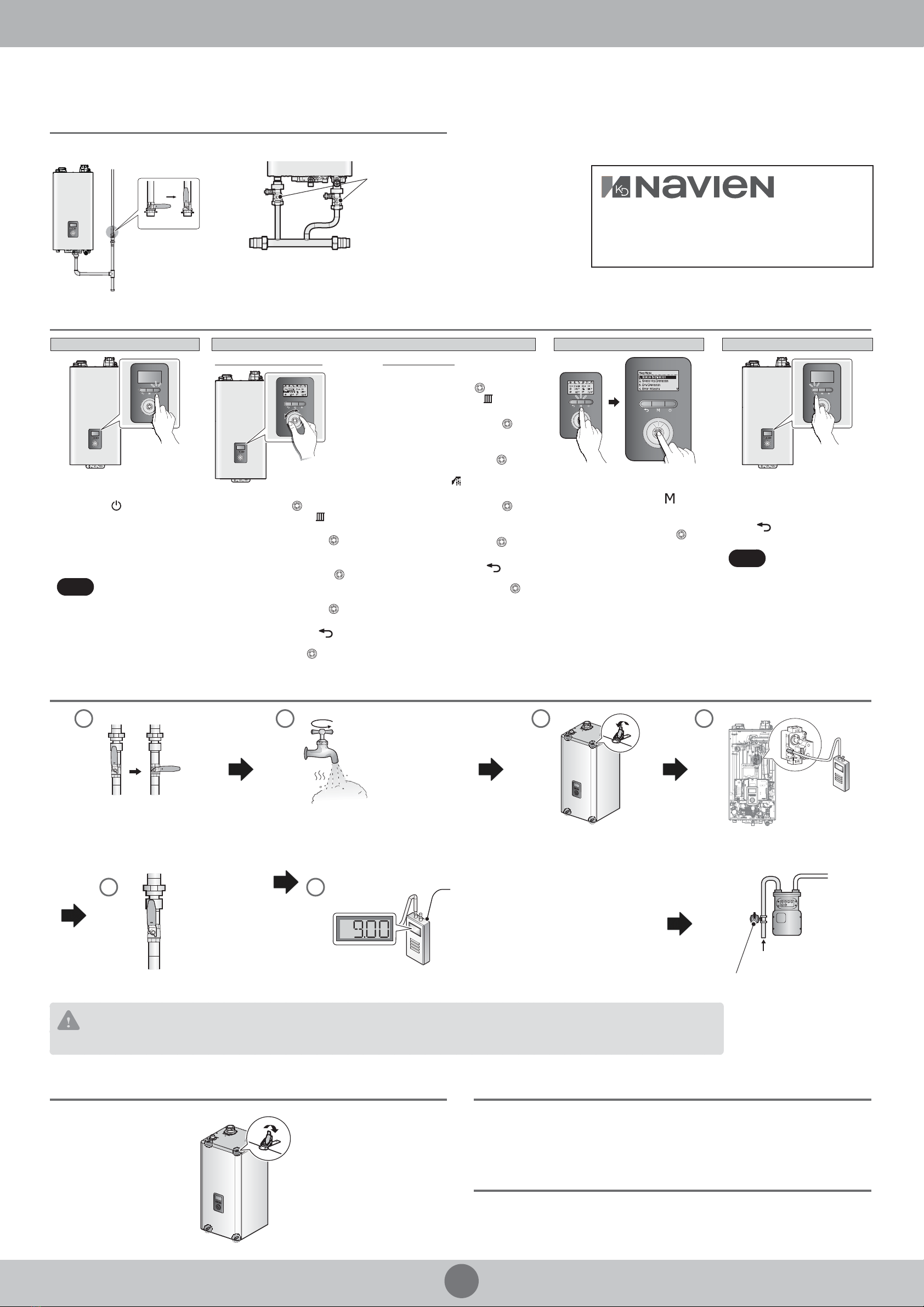
STEP 3 After Installing
󱂓Opening All the Valves
>
Gas Valve Space Heating System Valves
23(1
&/26(
2
3(1
&
/
26
(
23(1
&/26(
23(1
&/26(
Gas Valve
OpenedClosed
Shut-o
valves
Power ON Adjust Temperatures View Basic Information Resetting the Boiler
Space Heating Temperature DHW Temperature
1. In normal operation mode, rotate
the Command dial ( ). The space
heating temperature ( ) is
highlighted on the screen.
2. Rotate the Command dial ( ) to
the right to select the DHW
temperature.
3. Press the Command dial ( ) to
select the indirect DHW
temperature ( ). The highlighted
section will ash.
4. Rotate the Command dial ( )to
the right or left to increase or
decrease the temperature.
5. Press the Command dial ( ) to
conrm the new temperature.
6. Press the Back button ( ) to
return to normal operation mode,
or rotate the Command dial ( )
to adjust other operation
conditions.
To turn the boiler on, press the
Power button ( ).
When the power is on, the boiler
automatically enters normal
operation mode, and the boiler’s
operating conditions are displayed
on the screen.
Note
The setup wizard should
run the rst time the unit
is powered on. The wizard
must be completed
before the boiler can be
used. Refer to page 108 in
the Installation &
Operation Manual.
1. In normal operation mode, rotate the
Command dial ( ). The space
heating temperature ( ) is
highlighted on the screen.
2. Press the Command dial ( )to select
the space heating temperature. The
highlighted section will ash.
3. Rotate the Command dial ( )to the
right or left to increase or decrease
the temperature.
4. Press the Command dial ( )to
conrm the new temperature.
5. Press the Back button ( ) to return
to normal operation mode, or rotate
the Command dial ( ) to adjust
other operation conditions.
1. Press the Menu button ( ), and
then select “1. Status
Information”.
2. Rotate the Command dial ( ) to
switch between the information
items.
If an error message appears during
boiler operation, reset the boiler to
resolve the problem. Press the Back
button ( ) on the front panel to
reset the boiler.
Note If resetting does not
solve the problem, refer
to the troubleshooting
section of the User’s
Information Manual or
contact the service
center.
23(1
&/26(
23(1
&/26(
1
Open Closed
2
Open a hot water
faucet. The boiler
should turn on and
the gas in the gas
supply line will be
purged.
3 4
Digital pressure
manometer
Shut o the manual gas valve. Leave the faucet on until the boiler shuts down
due to a lack of gas supply, and then turn o the
hot water faucet.
Unfasten the 4 latches (2 at the top
and 2 at the bottom) to remove
the front cover and gain access to
the internal components.
Loosen the screw indicated in the gure and
connect a manometer to the pressure port.
Reset the manometer to zero before use.
23(1
&/26(
5
Open
Re-open the manual
gas valve and check
for leaks.
Activate multiple
zones to ramp the
boiler up to its
maximum ring rate.
6
NG: 3.5”–10.5”WC
LP: 8.0”–13.0”WC
Recommended
Gas Pressure Settings:
When the boiler reaches its maximum ring rate,
check the inlet gas pressure reading on the manometer.
If not,
Gas supply
Adjust the inlet gas pressure with gas regulator.
CAUTION
The boiler cannot function properly without sucient inlet gas pressure. Measuring the inlet gas pressure should be performed by a licensed professional only.
Navien, Inc.
20 Goodyear, Irvine, CA 92618
Tel: 1-800-519-8794, Fax: 1-949-420-0430
www.navieninc.com
󱂖Installing the Front Cover
>
󱂗Ensure Maximum Water Flow
>
After running the boiler for the rst 10 minutes, turn it o and clean the cold water lter
and the space heating return strainer to remove any trapped debris.
󱂘Final Check
>
A trial run should be performed in accordance with the Installation checklist listed in
the boiler’s Installation & Operation Manual.
󱂔Operating the Boiler
>
󱂕Measuring the Inlet Gas Pressure
>

Other manuals for NFC-250/175H

1

This manual suits for next models

1

Other Navien Boiler manuals

Navien NFC-250/175H User manual

Navien

Navien NFC-250/175H User manual

Navien NBH Series Guide

Navien

Navien NBH Series Guide

Navien NCB-24LSWE User manual

Navien

Navien NCB-24LSWE User manual

Navien NHB-150 User manual

Navien

Navien NHB-150 User manual

Navien NFB-175 User manual

Navien

Navien NFB-175 User manual

Navien NCB300-28K User manual

Navien

Navien NCB300-28K User manual

Navien NCB-150E User manual

Navien

Navien NCB-150E User manual

Navien NHB H Series User manual

Navien

Navien NHB H Series User manual

Navien CH-180 User manual

Navien

Navien CH-180 User manual

Navien NCB-24LSWE User manual

Navien

Navien NCB-24LSWE User manual

Navien NCB-240 User manual

Navien

Navien NCB-240 User manual

Navien NCB700-42C User manual

Navien

Navien NCB700-42C User manual

Navien NFC-250/200H Guide

Navien

Navien NFC-250/200H Guide

Navien NFC-175 User manual

Navien

Navien NFC-175 User manual

Navien NCN-21K(A) User manual

Navien

Navien NCN-21K(A) User manual

Navien CH-180 User manual

Navien

Navien CH-180 User manual

Navien NCB-700-2S+/42K User manual

Navien

Navien NCB-700-2S+/42K User manual

Navien NCB-150E User manual

Navien

Navien NCB-150E User manual

Navien NCB-180 User manual

Navien

Navien NCB-180 User manual

Navien NFC-200 User manual

Navien

Navien NFC-200 User manual

Navien NHB-55 User manual

Navien

Navien NHB-55 User manual

Navien NCB300-28K User manual

Navien

Navien NCB300-28K User manual

Navien CH-180 Mounting instructions

Navien

Navien CH-180 Mounting instructions

Navien NHB-110 Guide

Navien

Navien NHB-110 Guide

Popular Boiler manuals by other brands

Heatmaster 200 F Installation and operating instructions

Heatmaster

Heatmaster 200 F Installation and operating instructions

Rotex A1 BO 15bio operating manual

Rotex

Rotex A1 BO 15bio operating manual

Buderus Logamax plus GB142-24 installation guide

Buderus

Buderus Logamax plus GB142-24 installation guide

Beretta Mynute Green 50 R.S.I Installation and user manual

Beretta

Beretta Mynute Green 50 R.S.I Installation and user manual

Ferroli ECONCEPT 51 A Instructions for use, installation and maintenance

Ferroli

Ferroli ECONCEPT 51 A Instructions for use, installation and maintenance

Burnham Alpine ALP080 Brochure & specs

Burnham

Burnham Alpine ALP080 Brochure & specs

IDEAL MINI C28 Installation and servicing

IDEAL

IDEAL MINI C28 Installation and servicing

FireBird Systempac 12-20kW Technical manual

FireBird

FireBird Systempac 12-20kW Technical manual

Crown Boiler DG-38-EI installation instructions

Crown Boiler

Crown Boiler DG-38-EI installation instructions

Qualtex MIS882 user manual

Qualtex

Qualtex MIS882 user manual

Fondital Nias Dual BTFS 24 manual

Fondital

Fondital Nias Dual BTFS 24 manual

Beretta MYNUTE X C Series installer and user manual

Beretta

Beretta MYNUTE X C Series installer and user manual

Climit 24 OF User instructions

Climit

Climit 24 OF User instructions

Halstead CLUB HE 18 Installation and servicing instructions

Halstead

Halstead CLUB HE 18 Installation and servicing instructions

Viessmann B1KE Combi Series Installation and service instructions

Viessmann

Viessmann B1KE Combi Series Installation and service instructions

REMEHA Gas 310 ECO User guide lines

REMEHA

REMEHA Gas 310 ECO User guide lines

Slant/Fin INTREPID Installation and operating instructions

Slant/Fin

Slant/Fin INTREPID Installation and operating instructions

Hamworthy Purewell Installation, commisioning and maintenance instructions

Hamworthy

Hamworthy Purewell Installation, commisioning and maintenance instructions

manuals.online logo
manuals.online logoBrands
  • About & Mission
  • Contact us
  • Privacy Policy
  • Terms and Conditions

Copyright 2025 Manuals.Online. All Rights Reserved.