Navman FISH 4100 User manual

NAVMAN
Installation and
Operation Manual
www.navman.com
FISH 4100 / 4150
English .............3
Français .........24
Español ..........46
Português ......68

NAVMAN FISH 4100 Installation and Operation Manual
2
FCCStatement
Note: This equipment has been tested and found to comply with the limits for a
Class B digital device, pursuant to Part 15 of the FCC Rules. These limits are
designedtoprovidereasonableprotectionagainst harmful interference in a normal
installation.Thisequipmentgenerates,uses and canradiateradiofrequencyenergy
and, if not installed and used in accordance with the instructions, may cause
harmful interference to radio communications. However, there is no guarantee
that interference will not occur in a particular installation. If this equipment does
causeharmfulinterferenceto radio ortelevisionreception,whichcanbedetermined
by turning the equipment off and on, the user is encouraged to try to correct the
interference by one or more of the following measures:
Reorient or relocate the receiving antenna.
Increase the separation between the equipment and receiver.
Connect the equipment into an output on a circuit different from that to
which the receiver is connected.
Consult the dealer or an experienced technician for help.
A shielded cable must be used when connecting a peripheral to the serial
ports.

FISH 4100 Installation and Operation Manual NAVMAN 3
Contents
1 Introduction ..................................................................................................... 4
2 Getting started ................................................................................................. 5
2-1Simulationmode .......................................................................................................... 6
3 Operation ......................................................................................................... 6
3-1ALARMS ..................................................................................................................... 7
3-2HISTORYscreen operation ......................................................................................... 7
3-3HISTORYscreeninterpretation ................................................................................... 8
3-4ZOOM screen ........................................................................................................... 11
3-5SONAR screen ......................................................................................................... 11
3-6NAVIGATEscreen .................................................................................................... 12
3-7DATAscreen(FISH 4150 only).................................................................................. 13
3-8RANGE menu ........................................................................................................... 13
4 SETUP menu.................................................................................................. 14
4-1ALARMSmenu.......................................................................................................... 14
4-2UNITS menu ............................................................................................................. 15
4-3KEY BEEP ................................................................................................................ 15
4-4FISH SYMBOL.......................................................................................................... 15
4-5CONTRAST menu .................................................................................................... 15
4-6LOG menu(FISH 4150only) ..................................................................................... 16
4-7INSTALLmenu .......................................................................................................... 16
4-8CALIBRATIONmenu (FISH 4150only)..................................................................... 17
4-9Resettingto factory defaults ...................................................................................... 17
5 Installation ..................................................................................................... 18
5-1 What comes with this NAVMAN fishfinder?............................................................... 18
5-2Optionsand accessories ........................................................................................... 18
5-3Mounting the NAVMANfishfinderdisplay unit............................................................ 18
5-4Wiring connection...................................................................................................... 19
5-5Connecting a FISH4150 to otherinstruments ........................................................... 20
Appendix A - Specifications ............................................................................ 21
Appendix B - Troubleshooting ........................................................................ 22
Appendix C - How to contact us ..................................................................... 91
NAVMAN fishfinders are set up with default units of feet, °F (Fahrenheit) and knots.
Please refer to section 4-2 of this manual to change the units.
IMPORTANT
It is the owner’s sole responsibility to install and use the instrument and transducers in a manner that will
notcause accidents, personal injury orproperty damage.Theuserof this productis solely responsible for
observing safe boating practices.
NAVMAN NZ LIMITED DISCLAIMSALLLIABILITYFORANYUSE OF THIS PRODUCT INAWAYTHAT
MAYCAUSEACCIDENTS, DAMAGE OR THAT MAYVIOLATE THE LAW.
GoverningLanguage:Thisstatement,any instruction manuals, user guides and other information relating
to the product (Documentation) may be translated to, or has been translated from, another language
(Translation). In the event of any conflict between any Translation of the Documentation, the English
language version of the Documentation will be the official version of the Documentation.
This manual represents the FISH 4100 and the FISH 4150 as at the time of printing. Navman NZ Limited
reserves the right to make changes to specifications without notice.
Copyright©2001NavmanNZLimited,NewZealand,Allrightsreserved.NAVMANisaregisteredtrademark
of NAVMAN NZ Limited.

NAVMAN FISH 4100 Installation and Operation Manual
4
1 Introduction
Congratulations on choosing a NAVMAN fishfinder.
For maximum benefit, please read this manual
carefully before installation and use.
This manual describes the installation and operation
procedures for the FISH 4100 and FISH 4150. The
manualgenerallyreferstobothproductsastheNAVMAN
fishfinder. The product name is used only when
describing features specific to that particular fishfinder.
TheNAVMAN Fishfinder
TheFISH4100is an ultrasonic fishfinder.It provides
powerfulsoftwareandalarge,high-resolutionscreen
with a zoom facility and a choice of fish symbols.As
well as detecting fish, the FISH 4100 measures the
water depth, battery voltage and engine hours.
TheFISH4150alsomeasuresthewatertemperature,
the boat speed and has two distance logs (Trip Log
and Total Log).
An installed NAVMAN fishfinder has two parts:
- The transducer attached to the hull.
- The display unit.
Thetransducergeneratesanultrasonicpulse(sound
that is above the hearing range of the human ear),
which travels down towards the bottom, spreading
out into a cone shape. When the pulse meets an
object, such as a fish or the bottom, some of the
pulse is reflected back up towards the boat and is
received by the transducer. The depth of an object
can be calculated by measuring the time between
sending the pulse and receiving its echo. The
NAVMAN fishfinder will detect the bottom down to
600 feet (180 metres), depending on the clarity of
the water, and the type of transducer used.
The strength of an echo can vary for a number of
reasons. Larger fish usually return stronger echoes,
assodofishinthemiddleofthecone,wherethepulse
isstrongest.Reasonsforweakechoesincludethefish
or object being in deep water or turbid water or in the
edge of the cone where the pulse is weakest. Turbid
water scatters the ultrasonic pulse and is difficult to
‘see’through.Turbiditycanbecausedbyairinthewater
(e.g.fromanotherboat'swake)orbymudinthewater.
Important
It is vital to the performance of the fishfinder that
the transducer is installed in the best location.
Please follow the instructions in the Transducer
Installation manual very carefully.
All of the NAVMAN 4000 Series fishfinders use new
proprietary SBN Technology for sonar processing to
improve signal enhancement, bottom recognition and
noiserejection.SBNTechnologyusesthelatestindigital
adaptivefilteralgorithmstoenhanceallreturnedsignals.
At the same time, SBN Technology uses active noise
controltorejectinterference,whichcanoftenbemistaken
by fishfinders for true returns. Using SBN Technology,
the NAVMAN fishfinder analyses the reflections from
each pulse, filters false returns and displays what is in
thewater under the boat.
The distinctions between the four levels of shading
help the user to better interpret what is in the water
and what type of bottom is under the boat.
Assistingwith navigation
The NAVMAN fishfinder can be used to find fish, to
locatefeaturesonthebottomsuchasreefsorwrecks
and to help recognize favourite fishing spots from
theprofile of thebottom.UsetheNAVMANfishfinder
to assist navigation by following the depth contours
marked on charts.
IMPORTANT NOTE ON USE. While the NAVMAN
fishfinder can be used as an aid to navigation,
accuracycanbeinfluencedbymanyfactorsincluding
the location of the transducer. It is the user’s
responsibility to ensure that the NAVMAN fishfinder
is installed and used correctly.
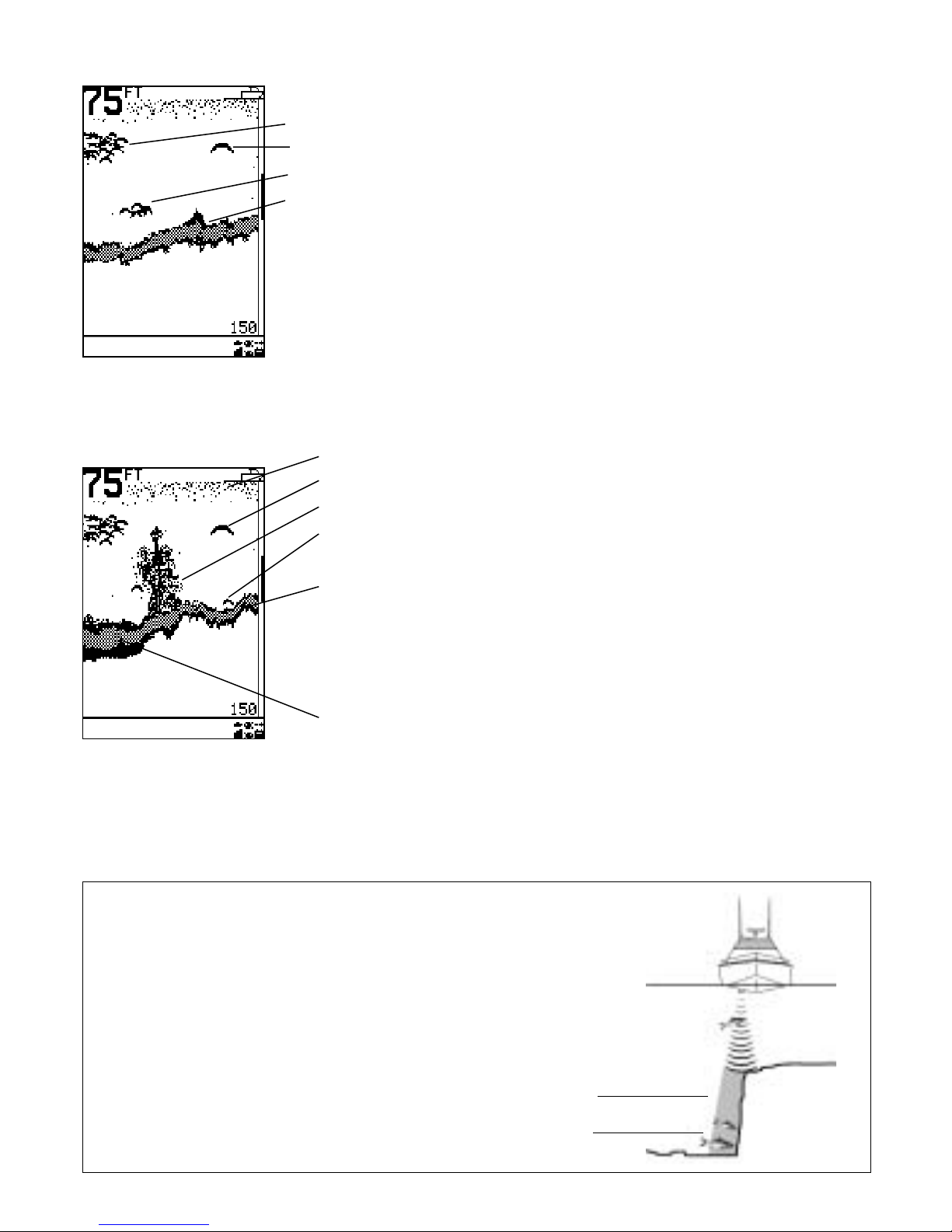
How to find fish
Underwater features like reefs, wrecks and rocky
outcrops attract fish. Use the NAVMAN fishfinder to
find these features, then look for fish by passing over
the feature slowly several times using the ZOOM
screen (see section 3-4). Where there is a current,
thefishwilloftenbefounddownstreamofthefeature.
For deep-sea fishing with the FISH 4150, a rapid
change in temperature may indicate the edge of a
warmorcoldcurrent.Thetemperaturedifferencecan
form a barrier which the fish may not swim through.
Search for fish on either side of the barrier.
Cleaningand maintenance
The NAVMAN fishfinder should be cleaned with a
dampclothormilddetergent.Avoidabrasivecleaners
andpetrolorothersolvents. Always coverorremove
a transom-mounted transducer when repainting the
hull. If painting over a through hull transducer with
antifouling paint then use only one coat of paint.
When repainting the transducer, remove previous
coats of antifouling paint by sanding it lightly.
When not in use, the NAVMAN fishfinder can either
be removed from the installation bracket and stored
ina safe, dry, cool place suchas the NAVMAN carry
bag, or left on the installation bracket and securely
covered. An optional sun cover, that also prevents
key depressions when in place, is available from
NAVMANdealers.

FISH 4100 Installation and Operation Manual NAVMAN 5
Power and transducer connection
FISH4100
One end of the integrated transducer / power cable
has an 8 pin LT connector plug. Push this plug into
the socket located on the rear of the display unit,
then turn the collar to lock. Make sure that the collar
is secure for a watertight connection.
FISH4150
One end of the power cable has a black 8 pin LT
connectorplug.Pushthis plug into the lower socket,
which has a black nut and is located on the rear of
the display unit, then turn the collar to lock. Make
sure that the collar is secure for a watertight
connection.
One end of the transducer cable has a blue 8 pin LT
connectorplug.Push thisplugintotheupper socket,
which has a blue nut and is located on the rear of
the display unit, then turn the collar to lock. Make
sure that the collar is secure for a watertight
connection.
If the transducer is not connected, the message
“NO TRANSDUCER DETECTED. ENTER
SIMULATION MODE?” will appear. Press to
switch between YES or NO. (More information on
the simulation mode can be found in the following
section). Press to confirm the selection and
the startup sequence will continue. (Note: If the
transducer was not intentionally disconnected,
turn the display unit off and refer to the section on
Troubleshooting inAppendix B, 9.)
Namesofkeys:
Cursor key
key
+Gain key
-Gain key
Power
Definition of Press and Hold in this manual:
·Press means to push the key for less than one
second.
·Hold means to push and hold the key down for
more than one second.
Power on
To turn the fishfinder on press .
Note: if the ignition wire is connected (see section
5-4) then the fishfinder will turn on automatically
when the boat's ignition is turned on.
A title screen briefly appears which displays basic
product information, including the software version.
The NAVMAN fishfinder then automatically displays
the screen that was last used.
Power off
To turn the fishfinder off, hold . A countdown box
appears. Continue to hold for 3 seconds until the
fishfinder turns off.
Note: if the unit is wired for Auto Power (see
section 5-4) the fishfinder can only be turned off
when the boat’s ignition is turned off.
Language selection
Tocheckwhich languageiscurrentlyselected, press
to display the MAIN MENU.
Follow these steps to change the language:
1. Power off the unit.
2. While the unit is off, hold down the key.
3. Keep holding down the key and power on
the unit.
4. The screen displays a list of languages.
Press the Cursor or key to highlight a
language, then press the Cursor key to
select it. The fishfinder will continue the
startup sequence.
For further information, (see section 4-7).
Backlighting
Use the button to adjust the backlighting to suit
individual preferences.
Press once, at any time, to see the backlight bar.
This is displayed at the bottom of the screen and
shows the current setting.
Press repeatedly until the desired backlighting
level is achieved. The backlight bar will disappear 2
seconds after the last press.
2 Getting started

NAVMAN FISH 4100 Installation and Operation Manual
6
An internal simulator allows users to learn how to
operate the fishfinder off the water.
InSimulationmode theword“SIMULATION”flashes
onthebottomofthe screen.Thefishfindergenerates
data so that all the main screens appear to be
operational. Any changes made to the contrast,
backlighting, alarms or the display setup are saved.
Turning Simulation on and off
FISH4100
Note: The FISH 4100 requires the use of the
optional Through Hull adapter cable wired to a
power supply of 12 V DC to access the Simulation
mode. Contact your nearest NAVMAN dealer.
FISH4150
Toturnthe Simulation mode on, power thefishfinder
off, disconnect the blue transducer plug at the rear
of unit, then turn the power on.
Toturnthe Simulation mode off,powerthefishfinder
off,reconnectthe blue transducer plug atthe rear of
the unit, then power the fishfinder on.
Usethisscreenfortakinga closer look atinteresting
underwater features.
SONAR screen (see section 3-5)
Displays the strength and depth of the echoes
returnedfromeachultrasonicpulse.Thedepthrange
is displayed in the lower right corner. This screen is
apowerfulaid,idealforshowingthebottomhardness
and the fish species.
This screen can also be used to adjust the display
shading on the HISTORYand ZOOM screens.
NAVIGATEscreen(seesection 3-6)
Prominently displays the water depth as a digital
readout. The corresponding bottom trace is also
shown. These two complimentary features are
particularly useful for understanding depth trends
when travelling at speed.
The FISH 4100 and 4150 display the engine-hours
counter, boat battery voltage and enabled alarms.
The FISH 4150 also displays the boat speed.
DATA screen (see section 3-7)
(FISH 4150 only)
The DATA screen displays the water temperature
and water temperature history over the last 40
minutes.It alsodisplaystheboatbatteryvoltage,log,
engine-hours counter, boat speed and water depth.
SETUP menu (see section 4)
UsethisoptiontocustomizetheNAVMANfishfinder
to suit the boat and individual preferences.
RANGE menu (see section 3-8)
UsethisoptiontoselecteitherAutoorManualRange
and to change the selected depth range.
MAIN MENU screen
TheNAVMANfishfinderis menudriven.Press
to display the MAIN MENU screen. The FISH 4100
MAIN MENU is shown:
The FISH 4150 has an extra option: DATA.
Press or to highlight an option, then press to
select it.
TheMAINMENUoptionsaresummarizedbelowand
fully explained in the following sections.
HISTORY screen (see section 3-2)
Displaystheechoesreceivedovertime,withthemost
recent events on the right of the screen. Use this
screen when travelling to show the bottom so reefs,
wrecks and fish can be found.
ZOOM screen (see section 3-4)
This screen is split into two parts. On the right is the
Full Range Section which shows part of the
HISTORYScreenandtothe leftistheZoomSection.
3 Operation
2-1 Simulation Mode
Enabled alarms
(displayedonall
screens).

FISH 4100 Installation and Operation Manual NAVMAN 7
Alarmscanbeenabledtoautomaticallydetectcertain
conditions, such as the water being too shallow. The
trigger settings for the alarms can be defined to suit
the boat and individual preferences.
The FISH 4100 has four alarms, TOO SHALLOW,
TOO DEEP, FISHALARM and LOW BATTERY.
The FISH 4150 has two extra alarms,TEMP VALUE
and TEMP RATE.
The alarm symbols and beeper cycles for all of the
alarms are shown in section 4-1. The FISH ALARM
is three short beeps, theTOO SHALLOWALARM is
arapidcontinuousbeepwhileallothersare a slower
continuous beep.
When an alarm condition is met, then:
· the beeper sounds.
· theALARMS menu is displayed on the
screen with the activated alarm(s) flashing.
Press any key to acknowledge the alarm, stop the
Select MAIN MENU - HISTORY to display the
HISTORY screen.
The HISTORY screen displays the most recent
echoes on the right of the screen and the oldest
echoes on the left. These eventually disappear off
the screen.
Theverticalbarontheright edge of the screen is the
zoom bar. This shows the zoom range.To adjust the
zoom range see section 3-4.
3-1ALARMS beeping and remove the ALARMS menu. This does
not disable the alarm. The symbol will continue to
flash until the alarm condition is no longer present.
Alarmsautomatically re-enable
The TOO SHALLOW, TOO DEEP and LOW
BATTERY alarms automatically re-enable when the
value moves outside the alarm trigger setting.
The TEMP VALUE alarm automatically re-enables
when the temperature is more than 0.45°F (0.25°C)
above or below the alarm trigger setting.
The TEMP RATE alarm automatically re-enables
when the rate of temperature change falls below the
triggersetting bymorethan0.2°F(0.1°C)perminute.
Enabling Alarms and Changing Trigger
Values
Seesection4-1forinformationaboutenablingalarms
and changing the trigger values.
3-2 HISTORY screen operation the boat. This means that the HISTORY screen
display moves across the screen more quickly than
when the boat is travelling in deep water. In deep
water, the echoes take longer to travel between the
objectsand the boat, producing adisplaythatmoves
across the screen more slowly.
Note 1: Different fish symbols can be selected (see
section 4-4).
Note2:Thedepthofbottomcanbeadjustedfor keel
offset (see section 4-7).
Range
Range is the depth of water displayed vertically. The
NAVMAN fishfinder has two range modes, Auto
Range and Manual Range:
· InAuto Range, the fishfinder adjusts the depth
range automatically so that the bottom is always
shown in the lower part of the screen.The use
ofAuto Range is recommended.
· In Manual Range, the fishfinder shows only a
selected depth range. In areas of rapidly
changing bottom depth, such as the sea floor
around pinnacles, it can be useful to prevent
the screen from rescaling to always show the
bottom. If the bottom is deeper than the
specified depth range, it will not be shown on
the display screen.
To change the range mode, (see section 3-8).
TheHISTORYscreendoesnotshowa fixeddistance
travelled by the boat; rather, it displays what has
passedbelowtheboat duringacertainperiodoftime.
Theactual displaydependsupontheboat speedand
the depth of the water.
Asthe boattravelsthroughshallowwater,theechoes
haveless distance to travel between theobjectsand
Fish symbol
with depth
Selected depth range
42.75metres (0 to 150ft)
Alarms
Bottom
Zoom bar

NAVMAN FISH 4100 Installation and Operation Manual
8
Changing the Gain Mode
Gain (sensitivity) controls the amount of detail
displayedonthescreen.TheNAVMANfishfinderhas
two gain modes,Auto Gain and Manual Gain:
· In Auto Gain, the gain is automatically adjusted
to compensate for water depth and clarity. The
use ofAuto Gain is strongly recommended
when learning to use a fishfinder, or when
travelling at speed.
· In Manual Gain, the user can adjust the gain to
compensate for water depth and clarity. Manual
settings range from 1 to 9. High settings may
amplify normal background noise until it
appears as random pixels on the screen. The
ideal setting produces only a small number of
random pixels. Normally the best results with a
fishfinder are obtained in Manual Gain but
practice and experience are required to
understand how to adjust the gain correctly.
TochangebetweenAutoGainandManualGain,hold
+or -. The Gain mode will be displayed briefly at
the bottom of the screen.
WheninManualGainthegainsymbol isshown
at the top of the display, followed by the gain level.
Press +to increase the gain level or press -to
decrease the gain level.
FishArches
Inideal conditions and with Fish Symbols turned OFF,
afishpassingthroughthecone-shapedultrasonicpulse
is displayed on the screen as a fish arch:
As the fish enters the weak edge of the sonar cone it
generates a weak return signal that turns on the first
pixelonthefishfinderscreen.Astheboatmovescloser
to the fish the distance between the transducer and
the fish reduces and the return signal is displayed at
progressively shallower depths, producing the start
of an arch. When the fish is directly beneath the
transducer and in the middle of the beam then the
Fishdetectionanddisplay
Thefishsymboloptioncanbecustomized,orswitched
offaltogetherso that theechoes are not converted to
fishsymbolson thescreen.Section4-4explains how
to do this. The differences between Fish symbol on
and off are:
Fish Symbol ON
Using NAVMAN’s SBN sonar technology
the fishfinder analyses all return signals
and eliminates most false signals and
clutter so that remaining targets are most
likely fish. Depending on the strength of the
remaining signals, they are displayed as
either small, medium or large fish symbols
- with or without depth. Whilst the SBN
processing is very sophisticated it is not
foolproof and there will be times when the
unit will not be able to differentiate between
large air bubbles, rubbish containing air,
fishing floats etc. and genuine fish returns.
Fish Symbol OFF
For experienced users this will always
provide the best information as every sonar
return signal is displayed, whether it is
surface clutter, a thermocline or a fish.
returnedsignalisevenstrongersothe archbecomes
thicker.Asthefishpassesoutoftheconethereverse
happens with a progressively weaker and deeper
return.
In reality there are many reasons why fish arches
can’t be seen. For example:
· Poor transducer installation - please refer to
the Transducer Installation Guide.
· If the boat is anchored then fish will tend to
show on the display as horizontal lines as they
swim into and out of the transducer sonar
beam. Slow speeds in deeper water give best
fish arch returns.
· Range is important. It will be much easier to
see fish arches when using NAVMAN’s split
screen zoom mode to concentrate on a
particular section of water rather than just
displaying everything from the surface to the
bottom. Zooming increases screen resolution
and is necessary for good fish arches.
· It is almost impossible to get fish arches in
shallow water as the transducer sonar beam is
very narrow near the surface and fish do not
stay within the beam long enough to display an
arch. Several fish in shallow water tend to
display as randomly stacked blocks of pixels.
3-3 HISTORY screen interpretation

FISH 4100 Installation and Operation Manual NAVMAN 9
The following picture shows the HISTORY screen
with the fish symbols turned off:
Large school of fish
Single fish
Small school of fish
Bottom
Strengthof returned echoes
The shading indicates differences in the strength of
thereturned echofromthebottom.Agreychequered
pattern indicates a strong echo and solid black
indicates a weak echo. Fish symbols are always
shown in black.
Thestrengthof the returnedechovarieswithseveral
factors, such as:
· The size of the fish, school of fish or other
object.
· The depth of the fish or object.
· The location of the fish or object. The area
coveredbytheultrasonicbeamisapproximately
cone-shaped and echoes are strongest in the
middle.
· The clarity of water. Particles or air in the water
reduce the strength of the returned echo.
· The composition or density of the object or
bottom. Mud, weed and sand bottoms tend to
weaken and scatter the sonar signal, which
results in weaker returns. Rock or coral
bottoms concentrate the return signal for
strong returns.
Note that planing hulls at speed produce air bubbles
and turbulent water that bombard the transducer. The
resulting ultrasonic noise may be picked up by the
transducer and obscure the real echoes.
Shadows
Shadows are areas where the ultrasonic beam
cannot ‘see’. These include hollows on the bottom
or beside rocks and ledges where the strong echo
returned off the rock obscures the weaker echo of
the fish.
Whenlookingfor smallobjectsincludingfish,users
should consider that there are places where
fishfinders cannot ‘see’.
These fish will be hidden in the bottom echo.
Shadow - where objects are hidden in the bottom echo.
Surface clutter
Hard bottoms such
as rock or coral
show as wide
bandsat the
bottomof the
screen
Soft bottoms such
as mud, weed and
sand show as
narrow bands at
the bottom of the
screen
Small fish just off
the bottom
Kelp / weed
Large fish

NAVMAN FISH 4100 Installation and Operation Manual
10
1 minute ago 30 seconds ago Now
When the fish symbol option is
ON, any echo returned that fits
the profile of a fish is displayed
on the screen with a fish symbol.
Note: times indicated are for illustration only.
Air in water (e.g.
from wake)
1 minute ago Now
Time
NAVMAN fishfinders display the most recent events on
the right of the screen.
Moving boat
Stationary boat
When a boat is stationary, all bottom echoes will come from the same small
area of bottom. This will produce a flat bottom trace on the screen.
The appearance of the HISTORYand ZOOM screens
can be changed to suit individual preferences.

FISH 4100 Installation and Operation Manual NAVMAN 11
Select MAIN MENU - ZOOM to display the ZOOM
screen.
TheZOOMscreenis split into twoparts.Onthe right
is the full range section (just like the HISTORY
screen) and on the left is the zoom section.
Full range section
Zoom section
Zoom bar
The full range section illustrated is 42.75 m (150 ft)
and the zoom bar, located on the right edge of the
screen, shows the area that is enlarged in the zoom
section,inthiscase the section between 18.6 m and
27.7 m (61 ft and 91 ft).
The zoom section shows the area of interest (such
as fish or features close to the bottom) in greater
detail than the HISTORYscreen.
BottomLock
The zoom bar is normally locked to the bottom
(BottomLock) sothatthebottomis alwaysdisplayed
inthezoomsection, regardless of changes in depth.
ToturnBottomLockoff,press thenmovethezoom
bar to the desired position with or .
To turn Bottom Lock on, move the zoom bar down
until it touches the bottom and the message
“BOTTOM LOCK ON” briefly appears.
IfBottomLockis offand the bottom rises tomeetthe
zoom bar, the zoom bar will temporarily track the
bottom. This condition will cease when the depth
exceeds the original depth of the zoom bar.
Changing the Zoom
To increase magnification (make the zoom bar
smaller), press .To decrease magnification (make
the zoom bar bigger), press .
Alternatively, the zoom bar can be adjusted in the
HISTORYscreenbeforeswitchingtotheZOOMscreen.
3-4 ZOOM screen
SelectMAIN MENU-SONARtodisplay theSONAR
screen.
Thisis apowerfulfeatureandwith someexperience,
this screen can be used to identify both the type of
bottom and the fish species.
On the Sonar Echo section on the right side, the
strengthofanechoataparticulardepthisshownby
ahorizontallineatthatdepth.Astrongechoproduces
a long line, whereas a weak echo produces a short
line.BelowtheechoesthescreenshowstheShading
Bar.
Theleftside of thescreenistheFishHistory section.
Using the Shading Bar as a control, the fishfinder
interprets the echoes shown on the Sonar Echo
section and uses this information to draw the Fish
History section.
Recognizing the Type of Bottom
The bottom trace is the strongest echo shown in the
lower part of the left side of the screen.
A bottom trace with a wide chequered grey layer is
indicative of a hard bottom, because a hard bottom
returns strong echoes. Conversely, a soft bottom
producesmedium orweakechoes,whichareshown
by a narrower trace.
Small strong echo
(e.g. fish). This
usually flashes on and
off as the ultrasonic
pulse strikes the fish.
Large strong signal
(e.g.bottom)
Shading Bar
Recognizing the Type of Fish
Different species of fish have different sizes and
shapesofswimbladders.Theairintheswimbladder
reflects the ultrasonic pulse, so the strength of the
echo varies between fish species according to the
size and shape of the swim bladder. The sonar
displayonthe FISH 4100/4150is70pixels wide, so
it can show 70 levels of return echo strength, which
is a powerful feature.
When fishing among a school of fish and catching
them, note the fish species and the strength of the
echo that it returns on the fishfinder on the Sonar
Echoscreen.Then,thenexttimethatparticularreturn
on the fishfinder is seen, it is likely to be the same
fish species.
3-5 SONAR screen

NAVMAN FISH 4100 Installation and Operation Manual
12
AdjustingtheShading Bar
The Shading Bar is displayed as a horizontal bar in
the lower half of the screen. Use the Shading Bar to
choosethestrengthoftheechoestobedisplayed in
black on the screens. Echoes that are weaker are
displayed in black.
IncreasetheblackpartoftheShadingBarbypressing
if there are too few long (strong) echoes being
displayed.
Decrease the black part of the Shading Bar by
pressing iftherearetoomanylong(strong)echoes
being displayed.
Manual Gain
When Manual Gain is selected, increasing the gain
setting will result in more detail being shown on the
fishfinderdisplay. Decreasing the gainwillreduce detail
beingshown.See‘ChangingtheGain Mode’ in section
3-2 for more information on changing Gain settings.
Gain setting These strong echoes
will be shown in
chequered grey on the
Fish History screen
These medium echoes
will be shown in black
on the Fish History
section
The weak echoes within
this white section of the
shading bar will not be
shown - they are below
the threshold of where
the shading begins.
3-6 NAVIGATE screen
Select MAIN MENU - NAVIGATE to display the
NAVIGATE screen. The screen display is different
for the FISH 4100 and the FISH 4150.
The NAVIGATE screen displays useful information
while travelling at speed.
The FISH 4100 prominently displays the depth and
bottom. It also displays the engine-hours counter,
thebatteryvoltageand any alarms thatareenabled:
Depth can be displayed
in feet (FT), fathoms
(FA), or metres (M). Use
the SETUP - UNITS -
DEPTH menu to select
the required depth units
(see section 4-2).
TheFISH4150prominentlydisplaysthewaterdepth,
alsotheboatspeed,thebottomandanyalarmsthat
are enabled.
Speed is displayed
only on the FISH
4150. Speed can be
displayed in knots
(KN), miles per hour
(MPH), or kilometres
per hour (KPH). Use
the SETUP - UNITS -
SPEED menu to
select the desired
speed units (see
section 4-2).
Increasing Gain by
pressing +will move
the black bar to the
left and result in
weaker echoes being
displayed in the Fish
History section.

FISH 4100 Installation and Operation Manual NAVMAN 13
Select MAIN MENU - DATA to display the DATA
screen:
A graph displays the surface water temperature for
thelast40minutesandisupdatedevery30seconds.
The current water temperature is displayed above
the graph and is updated every second.
3-7 DATA screen (FISH 4150 only)
Thetemperaturecan bedisplayedin°F(Fahrenheit)or
°C(Celsius).UsetheSETUP-UNITS-TEMPERATURE
menutoselectthedesiredtemperatureunits(seesection
4-2).
Alarms that indicate a specific temperature, or rate
of change of temperature, may be enabled (see
section 4-1).
Log. One of two distance logs can be displayed:Trip
LogorTotalLog.Bothlogsareretainedinthefishfinder
memory when the FISH 4150 is switched off.
Use the SETUP - LOG menu to select the Trip Log
orTotal Log (see section 4-6).The Trip Log must be
reset manually (e.g. to record total mileage during a
season, or the distance travelled on this trip). Note
that the units displayed on each Log will correspond
with the Speed.
Speed can be displayed in knots (KN), miles per
hour (MPH), or kilometres per hour (KPH). Use the
SETUP-UNITS-SPEEDmenutoselectthedesired
speed units (see section 4-2).
Battery
voltage
Depth
Speed
SelectMAINMENU - RANGEtochangethemanual
range and adjust the selected depth range.
The range setup box is displayed. This shows the
depth of water displayed vertically and the range
mode setting.
3-8 RANGE menu TheNAVMAN fishfinder has two range modes,Auto
Range and Manual Range. The use ofAuto Range
is recommended. See section 3-2 for more details.
Tochange betweenAutoRangeandManualRange,
press .
TheManualRangemodeoffersthe user a choice of
pre-selected water depths. Use and to display
the options and select a water depth.
Press to exit.
Temperature
Temperature
Graph
Log
Engine
hours
Enabled
Alarms

NAVMAN FISH 4100 Installation and Operation Manual
14
UsetheSETUPmenutocustomizetheNAVMAN
fishfinder to suit the boat and individual
preferences.
On a FISH 4100 use the SETUP menu to:
· Specify the trigger settings for the alarms (4-1).
· Choose the depth units (4-2).
· Turn the key beep on or off (4-3).
· Choose the fish
symbol (4-4).
· Adjust the
display contrast
(4-5).
· Select language
and setup keel
offset (4-7).
SelectMAINMENU-
SETUPtodisplaythe
FISH 4100 SETUP
Menu. Press or
to select an option:
4 SETUP menu On a FISH 4150 use the SETUP menu to:
· Specify the trigger settings for the alarms (4-1).
· Choose the units for depth, temperature and speed
(4-2).
· Turn the key beep on or off (4-3).
· Choose the fish symbol (4-4).
· Calibrate the log, temperature and speed (4-6, 4-8).
· Select the Trip Log or
the Total Log (4-6).
· Zero the Trip Log or
zero all logs (4-6).
· Adjust the display
contrast(4-5).
· Select language, setup
keel offset and calibrate
speed and temperature
sensors (4-7, 4-8).
SelectMAINMENU-SETUP
to display the FISH 4150
SETUP Menu. Press or
to select an option:
Select MAIN MENU - SETUP -ALARMS to display the
available alarms. Press
or to select an option.
Alarms can be enabled to
automaticallydetectcertain
conditions, such as the
water being too shallow.
Trigger settings can be
definedtosuittheboatand
individualpreferences.The
FISH4100ALARMSmenu
is shown:
The FISH 4150 has two
extraalarms,TEMP
VALUEandTEMPRATE.
The beeper cycle is different for some alarms. All of
the alarm symbols and beeper cycles on the FISH
4100 are shown:
4-1ALARMS menu
When an alarm condition is met, then:
· The beeper sounds.
· TheALARMS menu is displayed on the screen
with the activated alarm symbol(s) flashing.
Press any key to acknowledge the alarm, stop the
beeping and remove theALARMS menu. This does
not disable the alarm. The symbol will continue to
flash until the alarm condition is no longer present.
Note:TheFISHALARM givesonlythree shortbeeps.
Alarmsautomatically re-enable
The TOO SHALLOW, TOO DEEP and LOW
BATTERY alarms automatically re-enable when the
value moves outside the alarm trigger setting.
The TEMP VALUE alarm automatically re-enables
when the temperature is more than 0.45°F (0.25°C)
above or below the alarm trigger setting.
The TEMP RATE alarm automatically re-enables
when the rate of temperature change falls below the
triggersetting bymorethan0.2°F(0.1°C)perminute.
Symbol Alarm Beeper Alarm condition is
Name Cycle met when:
Too 1/5sec the depth is less than
Shallow the alarm trigger value
Too 1/2sec the depth is greater
Deep than the alarm trigger
value
Fish 3 short an echo matches the
Alarm beeps profile of a fish
Low 1/2sec the battery voltage is
Battery less than the alarm
triggervalue
The alarm symbols and beeper cycles for the two
extra alarms on the FISH 4150 are shown:
Symbol Alarm Beeper Alarm condition is
Name Cycle met when:
Temp 1/2sec thetemperatureequals
Value the alarm trigger value
Temp 1/2sec the rate of change of
Rate temperatureequalsthe
alarm trigger value

FISH 4100 Installation and Operation Manual NAVMAN 15
Select MAIN MENU -
SETUP-UNITStodefine
thedepthunitsonaFISH
4100.
The temperature units
andspeedunitscanalso
be defined on a FISH
4150. The FISH 4150
UNITS menu is shown:
Press or to
highlight an option.
4-2 UNITS menu DEPTH
can be displayed in units of feet (FT), fathoms (FA),
or metres (M). Press to select the required depth
units.
TEMPERATURE
can be displayed in °F (Fahrenheit) or °C (Celsius).
Press to select the required temperature units.
SPEED
canbedisplayedinknots(KN),milesperhour(MPH),
or kilometres per hour (KPH). Press to select the
required speed units.
Note: Distance units will change automatically to
match the speed units.
4-3 KEY BEEP
SelectMAINMENU -SETUP-KEYBEEPto enable
or disable a single beep that audibly confirms a
keypress.
Press to select ON or OFF. The default setting is
ON.
Select MAIN MENU - SETUP - FISH SYMBOL to
display the fish symbol options for the screen
displays.
There are three options. Press to select:
· OFF
·.
·,
4-4 FISH SYMBOL OFF
Displays echoes directly as pixels on the screen.
Displays any echoes that match the profile of a fish
as a fish symbol. Echoes that are not recognized as
fish are displayed as pixels on the screen.
Displays any echoes that match the profile of a fish
as a fish symbol with the depth. Echoes that are not
recognised as fish are displayed as pixels on the
screen.
Select MAIN MENU - SETUP - CONTRAST to
display the contrast setting box and the current
setting.
The contrast level can be set at any level between
0 and 16. The default setting is 6.
4-5 CONTRAST menu Press or to increase or decrease the setting to
the required level. Then press to exit.
Flashing Light and/or External Beeper
(FISH 4150only)
If a secondary alarm indicator is required, a flashing
light and/or external beeper can be installed with a
FISH 4150. These can be positioned anywhere
suitable on the boat. For installation advice see
section 5-4.
Enabling Alarms and Changing Trigger
Values
Press or to highlight an alarm, then press to
select it. To enable or disable an alarm, press to
switch between ON and OFF.
To set the trigger value for anAlarm, press or to
increase or decrease the trigger value.
The alarm trigger value is retained even when the
alarm is disabled.

NAVMAN FISH 4100 Installation and Operation Manual
16
KEELOFFSET
Keel offset is the distance between the location of
the depth transducer and the point the displayed
depth is measured from.
Enter a keel offset value when the transducer is
locatedbelowthewater surface but a displayoftotal
water depth is required, or when the depth of water
below the boat's keel is required.
Press or to select KEEL OFFSET, then press
to display the keel offset box.
Negativevalues displaythedepthas measuredfrom
a point below the transducer (e.g. keel). Positive
values display the depth as measured from a point
above the transducer (e.g. water surface).
Press or to increase or decrease the value.
Use this menu at installation time, to select the
language and to enter the keel offset value for the
boat.
Select MAIN MENU - SETUP - INSTALL to display
themenu. The FISH 4100 install menu is shown.An
extraoption,CALIBRATION,isavailableontheFISH
4150to calibrate watertemperatureandboatspeed.
The FISH 4100 Install Menu is shown:
Press or to select an
option:
LANGUAGE
The following languages
are available: English,
French,Swedish,Italian,
Spanish, Portuguese,
Dutch, German and
Finnish.
Press or to highlight
the selected language,
then press to save
andexit.
Select MAIN MENU - SETUP - LOG to display the
available options.
Press or to select
an option:
LOG
Selects which log is
displayed on the DATA
screen,TOTALorTRIP.
Press to choose
between TRIP or
TOTAL. Both logs are
retainedintheNAVMAN
fishfinder but only the
selected log is
displayed.
ZERO TRIP LOG
Resetting the trip log will return the trip log value to
zero. The trip log is retained in the fishfinder memory
4-6 LOG menu (FISH 4150 only) so it retains the distance value if the fishfinder is
switched off during a trip. Therefore, the trip log needs
tobe resetmanuallyeachtime the user wishes to log
a trip.
Press or tohighlightZEROTRIPLOG,thenpress
to select it. The message box “ZERO TRIP LOG
YES” appears.
Press to selectYES or NO. Then press or
to reset the trip log and exit.
ZEROALL LOGS
Resetting both logs will return both the trip log and
the total log values to zero.
Press or to highlight ZERO ALL LOGS, then
press to select it. The message box “ZERO ALL
LOGS YES” appears.
Press to selectYES or NO. Then press or
toexit.
4-7 INSTALL menu
Water surface
Depth of transducer
Enter positive values to display depth as measured from a point above the transducer (e.g. Water surface).
Enter negative values to display depth as measured from a point below the transducer (e.g. keel).
Negative value
Transducer
Note: Boat illustrated uses a through hull transducer
Positive value
Use Keel Offset either when the
transducer is located below the
water surface but a display of
total water depth is required, or
when depth of water below the
boat’s keel is required.

FISH 4100 Installation and Operation Manual NAVMAN 17
Use this menu to
calibrate the water
temperature and the
boat speed.
SelectMAIN MENU -
SETUP - INSTALL -
CALIBRATION to
display the calibration
menu.
Calibratingthe
Temperature
The factory settings
should be sufficiently
accuratefornormalusage.Howevertocalibratethe
temperature readout, first measure the water
temperature.
Then,tocalibratethesetting, selectTEMPERATURE
then press to display the temperature readout box.
Press or to increase or decrease the value to
match the measured temperature.
(To change the temperature units between °F
(Fahrenheit)or°C(Celsius), usetheSETUP-UNITS
menu (see section 4-2).
Calibratingthe Speed
Use this to calibrate the boat's speed and log.
Calibration may be required because different hull
shapes have different flow characteristics.
Obtainanaccuratemeasurementoftheboat'sspeed
from a GPS receiver; by following another boat
travelling at a known speed; or by making a timed
run over a known distance.
Note that for accurate calibration:
· The speed from a GPS receiver should be
greater than 5 knots.
· The speed from another paddlewheel
transducer should be between 5 and 20 knots.
· Best results are achieved in calm conditions
where there is minimal current (best at high or
low tide).
Use or tohighlighttheSPEEDoption, thenpress
to display the speed readout box. Press or to
increase or decrease the readout to match the
independentspeedvalue.
Important
This option resets all of the following settings and
resetsthem to the manufacturer’sdefaultsettings.
Settings relating to water temperature and boat
speedarefortheFISH4150only.Speedanddistance
are related. For example, if knots are chosen as the
speed units, then distance is always measured in
nautical miles.
To reset the fishfinder to the manufacturer's default
settings, power off the fishfinder. Then hold and
power on while holding it.
Themessage“RESETTOFACTORYDEFAULTS?”
appears. If “YES” is highlighted, do nothing and the
fishfinder resets to the default settings. Otherwise,
press or to select YES.
GENERAL
Auto Gain ....................................................... ON
AutoRange .................................................... ON
Manual Gain .......................................................5
Bottom Lock ................................................... ON
KeyBeep ........................................................ ON
Contrast .............................................................6
Backlighting........................................................6
4-8 CALIBRATION menu (FISH 4150 only)
4-9 Resetting to Factory DefaultsUNITS
Temperature..................................................... °F
Depth ........................................................... Feet
Speed ..............................................................KN
Distance ......................................................... NM
ALARMS
Shallow Alarm .............................................. OFF
Shallow Alarm Value .....................................10 ft
Deep Alarm .................................................. OFF
Deep Alarm Value .........................................60 ft
Fish Alarm .................................................... OFF
Temp. Change Alarm ................................... OFF
Temp. ChangeAlarm Value........................ 5.0 °F
Temp. Alarm ................................................. OFF
Temp. Alarm Value ...................................... 80 °F
Low BatteryAlarm ........................................ OFF
BatteryAlarm Value .............................. 11.5 Volts
FISHSYMBOL .......................................
INSTALL
Keel Offset ...................................................0.0 ft

NAVMAN FISH 4100 Installation and Operation Manual
18
Correct installation is critical to the performance of
the NAVMAN fishfinder. There are two components
to install, the display unit and the transducer. It is
5 Installation vital to read the entire installation section of this
manual and the documentation that comes with the
transducer before attempting installation.
5-1 What comes with this NAVMAN fishfinder?
Optionaltransducers
· Through hull Speed/Temperature transducer.
· Through hull Depth transducer.
· In hull Depth transducer.
Otheroptions and accessories
· Flush mounting kit.
· Replacement paddle wheel.
· Suncover.
· Adapter cable for through hull transducer.
· Carrybag.
· Transducer extension cable (FISH 4150 only).
DepthRepeater
Repeater for Depth, Speed, Water Temperature,
Battery Voltage (for FISH 4150 only).
Please consult your NAVMAN dealer for more
information.
Standard configuration
· FISH 4100 or FISH 4150 display unit.
· Power cable (the FISH 4100 power cable
incorporates the transducer cable).
· Mountingbracket.
· Warranty registration card.
· This manual.
· Transducer.
· Transducer Installation Manual.
· Screws.
5-2 Options and Accessories
Mountingthebracket
1. Select a position where the display head will be:
· at least 100 mm (4 in) away from the
compass.
· at least 300 mm (12 in) away from any
radio transmitter.
· at least 1.2 m (4 ft) away from any antenna.
· easy to read by the helmsman and crew
while underway.
· protected from physical damage during
rough sea passages.
· easy to access the 12 volt power source.
· convenient to route the transducer cables.
2. Fix the mounting bracket onto the boat using
the three stainless steel screws. Do not
overtighten the screws, as the bracket may not
rotate.
5-3 Mounting the NAVMAN Fishfinder Display Unit
3. Push the display unit onto the mounting
bracket and tighten it firmly using the knob on
the mounting bracket.
4. Attach the cables.
Note: There is also an optional flush mount kit
available. Please consult your NAVMAN dealer for
details.
Removingthe NAVMANfishfinder
The NAVMAN fishfinder can be removed after each
useforprotectionagainsttheenvironmentorsecurity
reasons.
WhenremovingtheNAVMANfishfinder, ensure that
the plugs left in the boat are not exposed to the
elements. Push the attached dust covers over the
exposed ends of the plugs. Keep the display unit in
a dry clean place such as the optional NAVMAN
carry bag.
Power cable
(FISH 4150 only)
Mounting
bracket
Transducer
Unit
Screws

FISH 4100 Installation and Operation Manual NAVMAN 19
Warning
1 Amp fuses must be positioned where shown in
the wiring diagrams.
If possible, route the transducer cables away from
otherwiringon theboat.Electricalnoisefromengine
wiring, bilge pumps and other electrical equipment
can affect the unit.
Theshortestandmostdirect connectiontotheboat's
battery helps to minimize voltage drop. Do not lay
cable along the bilge.
Two wiring options are described in this section:
·Basic Wiring. This does not start the fishfinder
automatically when the boat ignition is
switched on and it disables the engine hours
counter.
·Auto Power Wiring. This must be used for
engine hours and fuel computer options.
Important
The NAVMAN fishfinder must be run off a 12 volt
battery and must not be run off a circuit without a
battery.
BasicWiring
This option is possible on both the FISH 4100 and
theFISH 4150.
AutoPower Wiring
This option is possible on both the FISH 4100 and
theFISH 4150.
Note: Green and white wires are on the FISH 4150
only.
5-4 Wiring Connection
Fuse
Fuse
Fuse Red
Yellow
Black
Main
switch
12 V DC
Black wire: Connect this to the negative battery
terminal.
Red Wire: Connect this to the 12 V positive battery
terminal after the main switch. Fit a 1 Amp fuse as
shown.
Yellow wire: Connect this to the black wire. This
disables the engine hours counter.
Poweron thefishfindermanuallywheneverthe main
switch is on.
Black wire: Connect this to the negative battery
terminal.
Red Wire: Connect this to the 12 V positive battery
terminal after the main switch. Fit a 1 Amp fuse as
shown.
YellowWire:To enabletheenginehourscounter and
start the fishfinder automatically when the ignition is
turned on, connect the yellow wire to the ignition
system,througha1Ampfuse.Notethatthefishfinder
cannot be turned off while the ignition is on.
FlashingLightand/or External beeper
(FISH4150only)
Use the green wire on the FISH 4150, if desired, to
connect a secondary alarm indicator such as a
flashinglight or a 12 V external beeper with a builtin
drive circuit. Refer to the wiring diagram. If the
external beeper or light requires more than 250 mA
dctotal,fita12Vrelay.ConsultyourNAVMANdealer
for more advice.
NMEAInstruments(FISH4150 only)
Use the white wire on the FISH 4150, if desired, to
connect the fishfinder to other NMEA instruments
such as the NAVMAN depth repeater. See section
5-5 for more information.
White (NMEA out)
Green
External Beeper
or Light
Red
Yellow
Black
Main
switch
12 V DC
Ignition
switch
To ignition system

NAVMAN FISH 4100 Installation and Operation Manual
20
Several NAVMAN instruments can be connected
togetherto share data such as Depth orSpeed.The
FISH 4150 fishfinder uses the NMEA protocol to
output data to other instruments.
NMEA
NMEAis an industry standard for marine instrument
communications. Data sent by one instrument over
5-5 Connecting a FISH 4150 to other instruments
an NMEA line can be read and displayed by another
instrument that accepts NMEA0183 Version 2.
Depth, speed and temperature data is output by the
FISH 4150 and can be read and displayed by the
NAVMANREPEAT3100,DEPTH41, GPS
Chartplotter, or other NMEAinstrument.
REPEAT 3100
Repeaterfordepth, speed, watertemperatureand
batteryvoltage.
DEPTH41
Depthrepeater.
Please consult your NAVMAN dealer for more
information.
Please contact your NAVMAN dealer for information on NAVMAN’s full range of NMEAenabled instruments
and connection options.
Other manuals for FISH 4100
1
This manual suits for next models
1
Table of contents
Other Navman Fish Finder manuals

Navman
Navman TRACKFISH 6500 User manual

Navman
Navman TRACKFISH 6600 User manual

Navman
Navman Datahelm 8120 User manual

Navman
Navman FISH 440 User manual

Navman
Navman TRACKFISH 6600 User manual

Navman
Navman TRACKFISH 6500 User manual

Navman
Navman FISH 4200 User manual

Navman
Navman F400 User manual

Navman
Navman FISH 450 Tricolor User manual

Navman
Navman Fish 4350 User manual