NDB Technologie XDP-II User manual

XDP-II User’s Guide
NDB Technologie Inc. 02/04/08 1
PARTIAL
DISCHARGE DETECTOR
XDP-II
User’s Guide
Version 7.2
March 2009
NDB Technologie Inc.
1405 St-Jean Baptiste St., suite 111
Québec, QC
G2E 5K2, Canada
Phone: (418) 877-7701
Fax: (418) 877-7787
http://www.ndbtech.com

XDP-II User’s Guide
NDB Technologie Inc. 02/04/08 2
XDP-II User’s Guide
Copyright © 2006, and published by:
NDB Technologie Inc.
1405 St-Jean Baptiste St., suite 111
Québec, QC
G2E 5K2, Canada
Phone: (418) 877-7701
Fax: (418) 877-7787
http://www.ndbtech.com
Last Edition, March 2009
Document no: XDP-II rev. 7.2

XDP-II User’s Guide
NDB Technologie Inc. 02/04/08 3
TABLE OF CONTENTS
1. Introducing the XDP-II.............................................................................................. 4
1.1. Partial Discharges............................................................................................. 4
1.2. The XDP-II ........................................................................................................ 4
1.3. Applications....................................................................................................... 4
2. Product Overview..................................................................................................... 5
2.1. Equipment and Accessories.............................................................................. 5
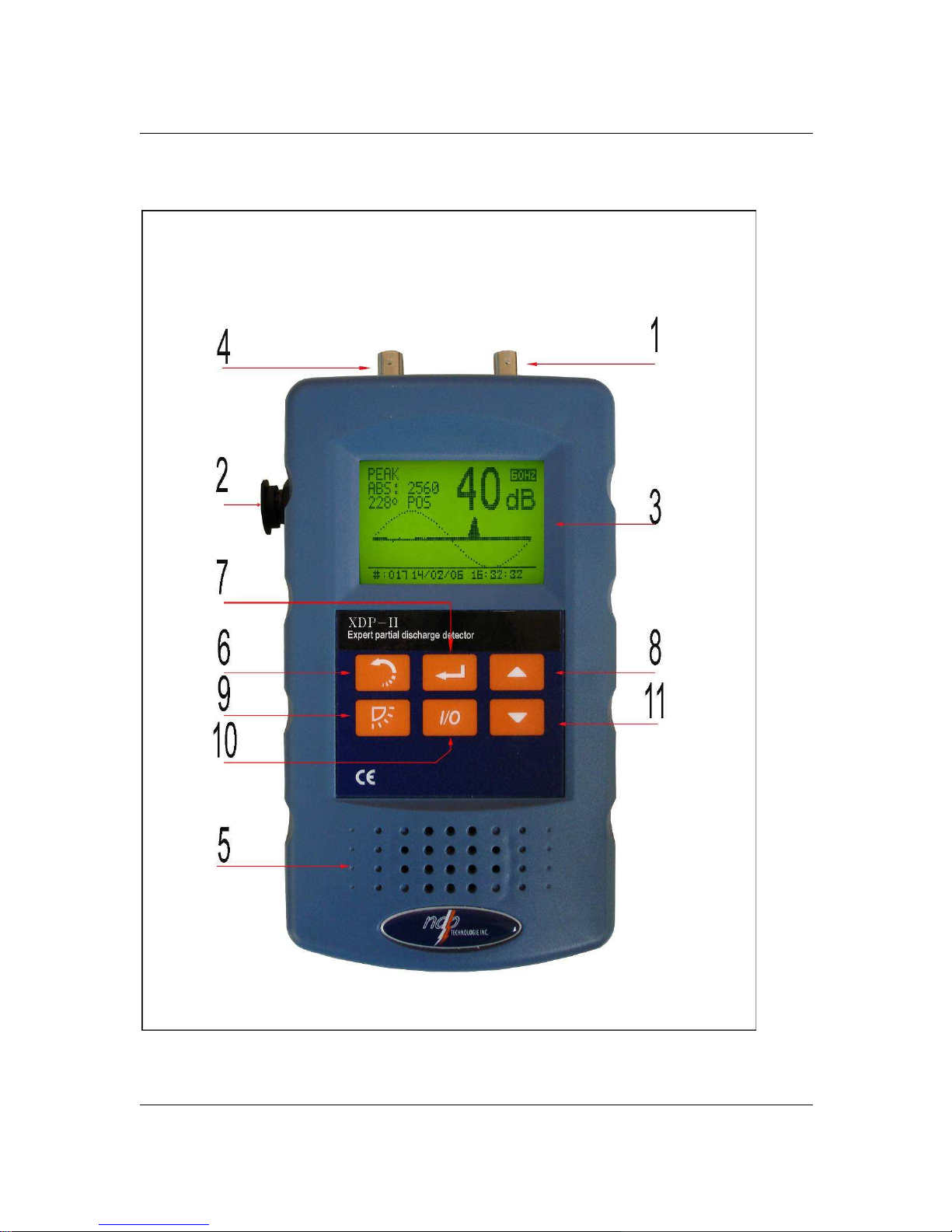
2.2. XDP-II Overview................................................................................................ 6
3. Calibration Check (when using xdp-302 capacitive sensor)..................................... 8
4. XDP-II Main Functions and Modes........................................................................... 9
4.1. Menus: .............................................................................................................. 9
4.2. Peak-Angle Mode.............................................................................................10
4.3. Analysis Mode..................................................................................................12
4.4. Edge Mode.......................................................................................................12
5. Applications.............................................................................................................13
5.1. XPLE/EPR TYPE Cable splice & elbow PD check...........................................13
5.2. Filters ...............................................................................................................14
5.3. Off-line partial discharge test kit (using a variable transformer) .......................16
5.4. Off-line partial discharge test kit (using a PD free source) ...............................20
5.5. Switchgears......................................................................................................24
6. Technical Specifications..........................................................................................25
6.1. XDP-II Characteristics......................................................................................25
6.2. Batteries...........................................................................................................25
6.3. Specifications...................................................................................................26

XDP-II User’s Guide
NDB Technologie Inc. 02/04/08 4
1. INTRODUCING THE XDP-II
1.1. PARTIAL DISCHARGES
Partial discharges (PD) occur between layers of isolation that have different
characteristics. They can gradually lead to the deterioration of the insulating
material’s dielectric properties.
1.2. THE XDP-II
The XDP-II detects quick variations of electrical fields caused by partial
discharges. It can also be used to locate partial discharges on isolated
equipment. In maintenance programs, it allows the monitoring of decaying
equipment, hence providing a safer environment for workers.
The partial discharge signal is detected by a capacitive coupling, and then
amplified by the XDP-II in a radio frequency bandwidth. The signal amplitude is
proportional to the discharge energy. The XDP-II can display this level of
discharge in dB or in picocoulombs (pC) if pC mode is selected in the calibrated
set-up.
1.3. APPLICATIONS
The XDP-II can be used to detect partial discharges in the following applications:
•XLPE cable, joint elbows
•Transformers
•Insulators
•Surge Arresters
•Switchgears
•Etc.

XDP-II User’s Guide
NDB Technologie Inc. 02/04/08 5
2. PRODUCT OVERVIEW
2.1. EQUIPMENT AND ACCESSORIES
The following standard components are provided with the XDP-II:
•A 12 V AC/DC adapter
•User’s guide
Fig 2.0
The following options are also available for the XDP-II:
•Capacitive spatula sensor
•Reference module with BNC-BNC adapter
•Inductive sensor
•Differential sensor
•Capacitive coupler (50 kV)
•BNC cable
•Nylon mesh pouch with transparent protection membrane
•Handling rod
•Customized sensor (according to application)
•Waterproof case
•XDP-II Software

XDP-II User’s Guide
NDB Technologie Inc. 02/04/08 6
2.2. XDP-II OVERVIEW
Figure 2.1: XDP-II overview

XDP-II User’s Guide
NDB Technologie Inc. 02/04/08 7
LABEL NAME AND DESCRIPTION
1 REFERENCE CONNECTOR: The reference module is connected
to this output when doing an equipment inspection.
2 CHARGER PLUG: 12V DC battery charger connection and
software PC connection via serial port.
3 LCD DISPLAY: Displays the intensity level of the discharge both in
dB and on a bar graph, and also shows the waveform of the signal
and indicates the battery level.
4 SENSOR’S CONNECTOR: Spatula or coupler connection.
5 SPEAKER: Allows the user to listen to the signal.
6 BACK: Send back to the preceding menu level, when in the menu
options. This key can also give the absolute value related to the
dB.
7 ENTER: Selects options in the menus.
8 UP / VOLUME (+): When used in the default reading mode, raises
the speaker's volume. When used in the menus, sends to the
upper option.
9
BACKLIGHT: Toggles the backlight on and off: press once to get
50% intensity, twice to get 100% intensity and press one more time
to turn it off. Please note that the backlight shuts off automatically
after 45 seconds.
10 I/O: Turns the XDP-II on and off.
11 DOWN / VOLUME (-): When used in the default reading mode,
lowers the speaker's volume. If used in the menus, browses menus
and submenus.

XDP-II User’s Guide
NDB Technologie Inc. 02/04/08 8
3.
CALIBRATION CHECK
(WHEN USING XDP-302 CAPACITIVE SENSOR)
When the XDP-II is turned on, it emits a signal at the reference module’s output. It
is recommended to compare the XDP-II with the reference value on a regular
basis. You need to perform the following steps to verify your XDP-II upon arrival
and whenever deemed necessary:
1. Connect the reference module.
2. Then connect the spatula sensor.
3. Place the sensor on the module in a way to make it cling around it as
much as possible (See Figure 3.0).
4. Turn the XDP on by pressing the
I
/
O
key.
5. Verify that the value displayed by the XDP-II is identical to the value
given on the sensor’s case.
6. Disconnect the reference module after testing.
Note: The test signal lasts thirty seconds and immediately starts after the activation of
the XDP-II. If you do not have time to complete the test during this time, you will
have to reset the XDP-II by turning it off and on again. It is important to mention
that the auto-test cannot be interrupted. You can have access to the menus even
if the auto-test is not finished.
Fig. 3.0: Testing the reference value
•If the reading is not identical to the value on the sensor
(+/-2dB), change the sensor and restart the test
procedure.
•If the test fails with a different sensor, please contact
NDB Technologie Inc.

XDP-II User’s Guide
NDB Technologie Inc. 02/04/08 9
4. XDP-II MAIN FUNCTIONS AND MODES
4.1. MENUS:
The XDP-II has five menus and many submenus that allow the user to
perform a variety of tasks:
SAVE:
This menu allows the user to record the signal by pressing the "
ENTER
" key.
The XDP-II saves the recording in its memory, assigning it with a
sequential number and the current date and time of the recording in hours,
minutes and seconds.
MODE:
Four different modes can be selected from this menu. More instructions on
these four modes are provided further in this chapter:
•PEAK-ANGLE
•CALIBRATION PICO
•ANALYSIS
•EDGE
FILE:
Thanks to this function, the user can listen to signals previously saved as
well as signatures downloaded with the software. The up and down arrow
buttons are used to select the recordings. Three submenus can be
selected:
•OPEN FILE
•DELETE ALL
•REF. SIGNATURES
PARAMETERS:
This mode is used to define three different parameters for the XDP-II:
CYCLES TO
DISPLAY: Sets the number of cycles to be displayed in the
waveform graphic. Two, four or eight cycles can be
selected. The XDP-II software provides up to 16 cycles
view.
FREQUENCY: Sets the XDP-II according to the power frequency of
the country where it is used. (50Hz or 60 Hz). The ’10
sec’ frequency is used with very low frequency AC

XDP-II User’s Guide
NDB Technologie Inc. 02/04/08 10
HIPOTS.
POLARITY: Sets the polarity of the signal to be displayed on the
screen.
NORMAL:
Partial discharges on the screen will be absolute.
Therefore a negative pulse will be seen as being
positive.
BIPOLAR:
Both positive and negative discharges will be displayed
with a line in the middle of the screen.
POS ONLY:
Only positive discharges will be displayed.
NEG ONLY:
Only negative discharges will be displayed.
SYSTEM:
In this menu, the user can choose between four submenus:
DATE TIME: You can adjust the real-time clock on your XDP-II. This
setting is very important as the date and time are
automatically associated with the record number.
LANGUAGE: Sets the XDP-II system language. Five different
languages are available: English, French, Spanish,
German or Italian.
CONTRAST: Sets the contrast level of the LCD.
VERSION: Displays the XDP-II firmware version
.
4.2. PEAK-ANGLE MODE
Description
The peak-angle mode will display partial discharges by synchronizing with the line
frequency. It will display peak amplitude averages for every three degrees of a
cycle. This provides information on the phase angle at which the partial discharge
appears. This technique reduces the random noise signal that is unsynchronized
with the frequency network.

XDP-II User’s Guide
NDB Technologie Inc. 02/04/08 11
Procedure
The peak-angle mode needs to be used with either the XDP-012 Bi-phase
Coupler or the XDP-050 Capacitive Coupler. The XDP-II must have a direct
connection to be able to synchronize with the
line frequency.
1. Connect the XDP-II to your system.
2. Select menu and choose PEAK-ANGLE (Fig. 4.1).
3. Wait for synchronization and calibration to be completed before going to
the next step (Fig. 4.2 & Fig. 4.3).
Fig. 4.1 Fig. 4.2
4. Make sure the Sis visible on the top right corner of the screen. This
indicates that the XDP-II is synchronized to the network.(Fig. 4.3).
If synchronization cannot be achieved, the XDP-II will display “SCAN
SYNCHRO”. The synchronization is not possible without a special device
and interface for sampling network voltage.
5. Select the scan time by using the arrow keys. The available choices are:
1, 2, 3, 4, 5, 10, 20, 30 seconds or 1 min.
Please note that a longer scan time will allow you to get a better average.
6. Press
SELECT TO START
and wait until the scan is complete.
(Fig. 3 & Fig 4)
Fig. 4.3 Fig. 4.4

XDP-II User’s Guide
NDB Technologie Inc. 02/04/08 12
4.3. ANALYSIS MODE
In this mode, the signal acquired by the XDP-II is compared with its own signature
database. The XDP-II then displays, in percentage, the four nearest signatures
found. It also displays the correspondence with all ten signatures on a bar graph
as well as the intensity of the signal, in dB. As shown in Fig. 4.5, the signature
that best corresponds to the signal acquired by the XDP-II is
SIGNATURE
2. The
signatures are selected in the XDP-II software.
Fig. 4.5
4.4. EDGE MODE
Using a high frequency sampling, this mode displays the accurate graphic of the
partial discharge signal edge. One sample is taken every 30 ns and is displayed
on the graphic.
The shape of the pulse gives you information on the distance between the sensor
and the fault. As illustrated on Fig. 4.6, the fault is very close to the sensor as the
pulse is not ringing. In Fig. 4.7, you can see that the pulse is ringing, due to a
reflection.
Fig. 4.6: PD near the sensor. Fig. 4.7: PD far from the sensor 1ft

XDP-II User’s Guide
NDB Technologie Inc. 02/04/08 13
5. APPLICATIONS
5.1. XPLE/EPR TYPE CABLE SPLICE & ELBOW PD CHECK
It is strongly recommended to proceed to the calibration of XDP-II before entering
a manhole or a cable junction room. (See Calibration Check in chapter 3).
Any installation of new equipment in underground networks should be verified for
reliability and security purposes. To this effect, the XDP-II, with the use of its
capacitive sensor, can detect partial discharges (PD) that may occur if the
equipment is not properly installed. (See Figure 16).
Fig. 5.1: Capacitive sensor on an XLPE cable.
You only need to slide the spatula sensor along the cables to be inspected. It is
important for the sensor to be in close contact with the cables. You don’t need to
adjust the gain as this is done automatically.
The volume keys allow the used to adjust the sound level as needed.
•Always use the spatula sensor on isolated cables.
•For significant measurements, the XDP-II must be
used on live voltage cables.

XDP-II User’s Guide
NDB Technologie Inc. 02/04/08 14
Note: The XDP-II must be used in conjunction with a capacitive coupler for
all the following tests.
oA typical application of the XDP-II is to help identifying partial discharge activity
on cables. Two kinds of activities can be detected using the peak angle mode:
- An activity with partial discharges going to the ground of a cable.
- An activity with partial discharges going to the central conductor.
oA XLPE cable can be tested by applying a voltage to the cable until partial
discharges occur (inception voltage Ui). Analyzing where the partial discharges
appear in the cycle can help identifying if the fault is coming from the inside or
from the outside of the cable.
- Partial discharges located between 0 º and 180 º will be identified as a fault
going to ground (Fig. 5.2);
- Partial discharges located between 180 º and 360 º will be identified as a fault
going to the cable’s center conductor. (Fig. 5.3).
As shown in figure 5.2, many partial discharges happen at many different angles
but the XDP-II will only display the absolute value of the one with the highest
amplitude. The polarity will also be displayed. You will only see PEAK ABS when
the scan is complete, therefore if you selected a scan of 30 seconds, you will
have to wait 30 seconds to see PEAK ABS appearing.
Fig 5.2 Fig. 5.3
5.2. FILTERS
The use of filters with the XDP-II will eliminate outside noises not related to actual
partial discharges.
Filters must be connected as shown in Fig. 5.4

XDP-II User’s Guide
NDB Technologie Inc. 02/04/08 15
STANDARD FILTERS: 200 KHz to 2 MHz (XDP-049)
2 MHz to 20 MHz (XDP-048)
15 MHz to 40 MHz (XDP-052)
Custom filters may also be available upon request.
Fig. 5.4

XDP-II User’s Guide
NDB Technologie Inc. 02/04/08 16
5.3.
OFF-LINE PARTIAL DISCHARGE TEST KIT
(USING A VARIABLE
TRANSFORMER)
The off-line partial discharge test kit allows partial discharge measurements in
picocoulombs (pC). The XDP-II requires to be calibrated to perform these
measurements in pC. The capacitive coupler is designed to safely connect to the
XDP-II. The line frequency is attenuated by the coupler so partial discharge
measurements are risk-free for the user.
The following procedure explains how to calibrate and measure in pC.
Required equipment for PD test on distribution transformer using a variable
transformer:
1. XDP-II
2. Line filter (XDP-021 or 046)
3. HV capacitive coupler (XDP-050)
4. High-voltage cable (EWXDP050-02A)
5. 200pC calibrator (XDP-202)
6. 4mm extension (EWXDP203-02A)
7. Calibrator ground cable (EWXDP203-01A)
8. Integrator filter 2 MHz (XDP-205)
9. 2 BNC to BNC coaxial cables (EWXDP050-03A)
10. Line filter output cable (EWXDP021-01A)
11. Line filter cable (WIR-X-037)
12. Metal plate reference ground (XDP-206)
13. Low voltage variable transformer Option
Make sure that your equipment is properly grounded at all times.
Calibration set-up for transformer is illustrated below.
This mode is used to calibrate the XDP-II in order to see the measurements in
picocoulombs. The measurements in picocoulombs (pC) will match the initial
measurements in dB, which were taken during calibration check. Make sure that
the coupler’s head is not grounded during calibration.
Warning: The variable transfomer must be disconnected from the
network
during this operation.

XDP-II User’s Guide
NDB Technologie Inc. 02/04/08 17
1. Plug the filter integrator (XDP-205) direcly to the input of XDP-II and slide the
switch to the 0 dB position.
2. Connect the calibrator and the XDP-II. The device under test as well as the
high voltage transformer source must be properly connected for valid
calibration.
3. Make sure that the XDP-202 is connected to the coupler and select
CALIBRATION PICO
menu and then 200pC.
Select 200pC

XDP-II User’s Guide
NDB Technologie Inc. 02/04/08 18
4. Wait 20 seconds and then press
SELECT
to quit calibration.
5. Remove the XDP-202 from the coupler.
Note: With XDP-202 and XDP-205 calibrators, the reading should show
about 38 to 40dB.
The XDP-II is now calibrated with a signal of 40 to 50dB. Measurements in pC will
now vary along with those in dB.
Note: If you have 39dB for 200pC, the maximum value before overload is
2000pC. For higher values, use filter switch at -20dB attenuation and
recalibrate the XDP-II. The maximum value before overload is then
20,000pC.

XDP-II User’s Guide
NDB Technologie Inc. 02/04/08 19
Alow voltage is required to work with transformers (0 to 130V or 0 to 250V). A
variable transformer (Variac) is used to control the voltage connected to the
transformer secondary winding. The voltage is increased until partial discharges
appear.
Note: The XDP-II will shut down automatically after 15 minutes of inactivity. If
this occurs, calibration must be redone.

XDP-II User’s Guide
NDB Technologie Inc. 02/04/08 20
5.4.
OFF-LINE PARTIAL DISCHARGE TEST KIT
(USING A PD FREE
SOURCE)
Calibration is required in order to measure in pC with the XDP-II. The capacitive
coupler allows you to connect your XDP-II safely. The line frequency is
attenuated by the coupler so that you can measure partial discharges without any
risks.
The procedure below will show you how to calibrate and measure in pC.
Calibration procedure
Required equipment (when using a PD free source)
1. XDP-II
2. Line filter (XDP-021or 046)
3. HV capacitive coupler (XDP-050)
4. 200 pC calibrator (XDP-202)
5. 200 kHz to 2 MHz integrator filter (XDP-205)
6. 4 mm extension (EWXDP203-02A)
7. Calibrator ground cable (EWXDP203-01A)
8. 2 BNC to BNC coaxial cable (EWXDP050-03A)
9. 2-foot high-voltage cable (EWXDP050-02A)
10. 1.5-foot high-voltage cable (EWXDP050-01A)
11. 2 Line filter cable (WIR-X-037)
12. Grid plane (XDP-206)
13. High-voltage control source
14. High-voltage transformer source
Note: Make sure your equipment is properly grounded at all time.
The set-up for calibration is illustrated below.
This mode is used to calibrate your XDP-II in order to be able to see the
picocoulomb on the screen.The picocoulomb (pC) will match the initial dB taken
during calibration. Users have to make sure the coupler’s head is not grounded.
Table of contents
Popular Security Sensor manuals by other brands

mySmart
mySmart MWS3A-PRM-LV Product guide

EMX Industries
EMX Industries IRB-MON2 instruction manual

MITECH
MITECH MFD500 operating manual

Perenio
Perenio PECMS01 quick start guide

DMP Electronics
DMP Electronics 1125 Installation sheet

BEIJING CAP HIGH TECHNOLOGY
BEIJING CAP HIGH TECHNOLOGY KUB100 Series manual