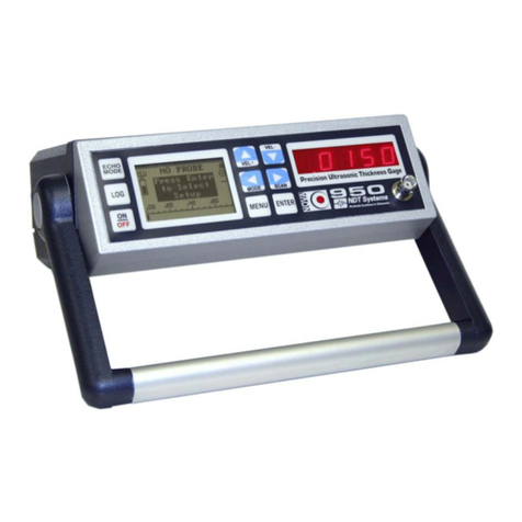
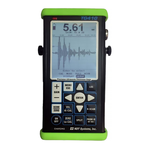
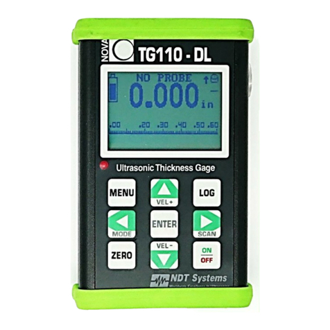
NDT Systems Nova Eclipse TG930 User manual

Nova Eclipse TG930 - Users Manual
1
Table Of Contents
1.0. INTRODUCTION ..........................................3
1.1 PrincipleofOperation ..............................3
1.1.1 Basics of Ultrasonic Thickness Gaging ........3
1.2 GeneralApplications ...............................5
1.3 MajorFeatures:....................................7
2. GETTINGSTARTED........................................8
2.1 LayOutShipmentContents..........................8
2.2 ConnectProbeandCable ...........................8
2.3 ReferenceStandards ...............................9
3. DISPLAY AND CONTROLS FAMILIARIZATION .................10
3.1 DisplayFeatures..................................12
3.2 Touch Commands .................................12
4. OPERATIONSTEPS.......................................13
4.1 Power On - Battery Check - Auto-Off .................13
4.2 ProbeCoupling...................................13
4.3 BasicMenu-SelectionsandControls .................14
4.4 CalibrationProcedures ............................18
4.5 THICKNESS MODE Sub-Menu: ......................19
4.6 ALARMSSub-Menu ...............................20
5. ADVANCED FEATURES ...................................21
5.1 ScrollingB-Scan..................................21
5.2 Data Logging .....................................22
5.3 MODIFYSETUP...................................26
5.4 UltrasonicVelocity..........................32
Longitudinal Ultrasonic Velocity Table .............33
6. GAGING TIPS AND TECHNIQUES ...........................34
6.1 ReferenceStandards ..............................34
6.2 Test Surface and Geometry Considerations ...........34
6.3 MaterialTemperatureEffects........................36
6.4 AdditionalTestMaterialFactors .....................36
7. GAGING PRECAUTIONS ...................................38
7.1 VeryThinSections ................................38
7.2 PittingCorrosion..................................38

Nova Eclipse TG930 - Users Manual
2
7.3 MaterialMisidentification...........................38
7.4 WornorMalfunctioningProbes .....................38
7.5 Material Stacks ...................................38
7.6 PlatedorPaintedMaterials .........................39
7.7 Abnormal or Unusual Thickness Readings ............39
8. ACCESSORIES ..........................................40
8.1 Standard Accessories .............................40
8.2 Optional Accessories ..............................40
9. PROBESAVAILABLE .....................................43
10. MAINTENANCE ..........................................45
WARRANTY ...............................................47
PRELIMINARY Rev 1.1
Nova Eclipse TG930 - Users Manual
3
1.0. INTRODUCTION
NDT Systems thanks you for your purchase of the NOVA TG930 handheld
Ultrasonic Thickness Gage, a precision instrument that provides exceptional
value and unmatched features. The TG930 provides ultra-high resolution
(0.0001 inch/0.001 mm) in a light-weight, handheld thickness gage found
only in larger, bulkier portables and bench-tops. The many additional
features contribute to the exceptional ease of operation and flexibility in
applications. The TG930’s rugged design assures dependable performance
for a wide variety of field and lab inspection requirements.
1.1 Principle of Operation
The NOVA TG930 enables measurement, display, evaluation, and recording
of corrosion and other conditions that can impair the safety and function of
countless structures, systems, and materials. Measurements are made with
access to only one accessible surface of the test object. A large selection of
high frequency single-element contact, delay-line, and bubbler-type
transducers can be used interchangeably to satisfy a multitude of
applications.
1.1.1 Basics of Ultrasonic Thickness Gaging
The NOVA operates on a principle similar to Sonar, but at much higher
frequencies (Megahertz range) and electronic speeds. An ultrasonic
frequency sound-beam is generated which emanates from the transducer
and is coupled into the test object.
High-frequency ultrasonic waves travel through monolithic materials at
essentially constant velocities, depending upon the type of material
supporting the ultrasonic wave. This fact provides the basis for accurately
measuring the thickness of metals and some non-metals, with access to only
one side of the test object.
The NOVA accurately senses the time interval between the initiation of a
short pulse of ultrasonic energy into the test object and the time taken to
travel through it. This time interval is short; for example, the velocity of
ultrasound in steel is approximately one-quarter inch (6.3 mm) in one
millionth of a second (one microsecond). Thus, in order for the NOVA to
accurately measure steel thicknesses from as small as 0.0050 inch to 20.00
inches (0.25 to 25 cm), it must have highly stable and accurate timing
circuitry. Think of it as a highly sophisticated, super-accurate stop-watch.
Attached to the NOVA is a cable connected to an ultrasonic transducer, or

Nova Eclipse TG930 - Users Manual
4
probe. The transducer has a thin wafer of a piezoelectric material at its
surface. Piezoelectric materials convert short pulses of electrical energy into
tiny mechanical displacements, and, conversely, from mechanical
displacements into electrical impulses. The probe acts both as transmitter
and receiver
When coupled to the surface of the test object – call it the entry surface – the
probe receives a short-duration electrical pulse from the pulser in the NOVA.
Fundamentally, the “clock” starts with this pulse. The ultrasonic sound-beam
begins its transit within the test object, induced by the electrical-to-
mechanical impulse generated by the transducer. The ultrasonic impulse
travels through the test object at a velocity characteristic of the material.
When it reaches a boundary – for example, the side of the test object
opposite the entry surface – the back surface – it reflects (echoes) back
toward the entry surface. As it impinges on the entry surface, the transducer
senses the tiny mechanical echo displacement and converts it into a small
electrical signal. In the receiver section of the NOVA, the “clock” is signaled
to stop. The time interval between the start and stop is converted into a
thickness measurement. The characteristic velocity of the test material –
distance divided by time (e.g., inches or millimeters per microsecond) –
divided by the round-trip transit time (microseconds) yields total distance
traveled. Since the total transit path is twice the actual thickness, it is
automatically divided by one-half and displayed as a decimal thickness. On
test objects with smooth, parallel surfaces, the displayed thickness is true
within the resolution of the last decimal place displayed.
Nova Eclipse TG930 - Users Manual
5
Functional Diagram
This round-trip time of the echo is linearly correlated to the test material's
thickness – the thicker the material, the longer the round-trip time. The
NOVA’s sophisticated circuitry precisely measures the round trip-time and
compensates for the characteristic ultrasonic velocity of the material being
gaged. The measured thickness is displayed, virtually instantaneously, on
the digital display and in the units selected, either inches or millimeters.
1.2 General Applications
The NOVA TG930 gages a wide range of thicknesses on metals, plastics,
ceramics, glass or virtually any other material which satisfactorily conducts
ultrasound, and has relatively parallel (or concentric) surfaces. Its high-
resolution capabilities make the NOVA TG930 uniquely applicable to gaging
very thin materials – for metals, as thin as 0.005 inch (0.13 mm) – with
resolution of 0.0001 inch (0.001 mm). However, it can also be effectively
used to gage thickness up to 20 inches (500 mm).
Small, local thickness variations, such as those caused by corrosion,
erosion, and certain types of internal flaws may also be detected. [9xx
Model-dependent: Later sections of this manual will detail a unique
feature of the NOVA that produces a cross-sectional view of the flawed
surface and the corresponding thickness reduction. Also included is

Nova Eclipse TG930 - Users Manual
6
the ability to record (log) numerous thicknesses and their
corresponding locations.]
The durable custom-extruded “Easy Grip” case design allows the unit to
withstand the rigors of heavier industrial environments, while its accuracy
makes it suitable for use in less rugged conditions.
Nova Eclipse TG930 - Users Manual
7
General applications include:
• Aircraft Structural and Engine Components
• Aircraft Windows
• Rocket and Spacecraft Components
• Machined, EDM, Mechanically Formed Parts
• Ceramics
• Certain Composite Materials
• Glass Plate and Tubing
• Plastic Shapes and Piping
• Boiler and Pressure Vessel Components
• Heat Exchangers
• Pipes and Tubing
• Petroleum, Gas, Water, Waste Storage Tanks
• Railcar Axles and Wheels, Railroad Rails
• Building and Bridge Components:
• Primary Metal Forms: Plates, Slabs, Billets, Bars, Blooms, Forgings,
Castings, Extrusions
• Marine Structures
• Ship Hulls, Decking, and Propulsion Components
1.3 Major Features:
• Membrane-sealed TOUCH-COMMAND controls simplify setup and use.
• 128 x 64 pixel, high contrast, graphic Liquid Crystal Display (LCD)
provides simple, plain text menus and easy readability of thickness
data.
• Backlight – automatic, or on/off selectable.
• Ultra-portability – a pocket-sized, handheld instrument incorporating
NDT Systems’ “Easy Grip” custom extruded aluminum case.
• State-of-the-art microprocessor-based design offers unparalleled, high
accuracy performance for numerous thickness gaging applications.
• Adjustable ScanBar feature produces a simple, analog-metered display
of thickness for easy and rapid view of thickness trends.
• Scrolling T-Scan (also known as “B–Scan”) – standard (patent pending)
– produces a cross-sectional image of a selected scan-path.
• Auto-Probe Recognition (patented) – Legacy Probe menu selection
enables use of many existing NOVA transducers.
• Adjustable velocity setting.
• 50,000 point Data Logger incorporating a scrollable “Spread Sheet”
view.
• Single or two-point calibration.
• High and low alarm limits. RS232 data transfer port permits up- and
down-loading of log data and software upgrades.

Nova Eclipse TG930 - Users Manual
8
The NOVA TG930 incorporates the latest technology available in
microprocessor design. Through sophisticated on-chip programming, the
microprocessor computes, linearizes, and directs numerous operations at
high speeds. It also offers intuitive, simplified setup, calibration, and
operation via the TOUCH-COMMAND pushbuttons and intuitive Menus.
The high-powered transmitter (pulser), high-sensitivity receiver, and
informative digital display function together with the microprocessor to
produce exceptional performance from a compact, light-weight, precision
measurement instrument.
2. GETTING STARTED
2.1 Lay Out Shipment Contents
Separate and lay out the NOVA TG930, probe(s), cable(s), couplant, and
any accessories ordered. The NOVA comes with two AA-size alkaline
batteries installed in its battery chamber.
2.2 Connect Probe and Cable
All probes, with the exception of “Mini-Probes”, use a detachable cable for
connecting to the TG930. Connect the cable to the probe. Connect the
other end of the cable to the corresponding receptacle located on top of the
gage.
Various probes are available to optimize performance for the broad spectrum
of gaging applications that may be encountered. The General Purpose
Delay-Line Transducer (D11) can be used for most applications
encompassing a thickness range in steel from approximately 0.0050 to 0.700
inch (0.130 to 1.780 mm), and for surface temperatures up to about 250ºF
(120ºC). The General Purpose Contact Transducer (C11) has a range of
approximately 0.062 inch to 20.000 inches (1.57 to 50.00 mm). It is
recommended to use the C11 Contact Transducer for the familiarization
procedures that follow.
For the extensive listing of probes for higher temperature and specialized
applications, see Section 9 of this manual.
Nova Eclipse TG930 - Users Manual
9
2.3 Reference Standards
To calibrate the NOVA TG930, it is necessary to have one or more known
thicknesses of the same material as that of the test object. Initial calibration
procedures require reference samples representative of the material to be
gaged.
Machined stepped-wedges having thicknesses across the range of interest
are convenient and commonly used reference standards. For the purposes
of familiarization with the NOVA TG930, it is recommended to use steel
stepped-wedges having several steps with thicknesses ranging from 0.020
to 0.500 inch (0.50 to 12.7 millimeters). Other stepped wedges
encompassing that general range of thicknesses can also be used. Such
standards are readily available or can be custom-produced. Contact NDT
Systems for further information.
For high-accuracy calibration and subsequent high-resolution
measurements, Users of high-resolution instruments, such as those in the
NOVA 900 Series, may be required to use thickness-certified precision gage
blocks and shims.
NOTE: Selection and use of reference standards is of primary
importance in order to calibrate and assure the accuracy of any
ultrasonic thickness gage. For more detailed discussion on the
selection and use of reference standards, see Section 6, Gaging Tips
and Techniques, and Section 7, Gaging Precautions.
2.4 Using Couplants
A couplant film is needed to transfer the high frequency ultrasonic energy
from the probe into the test material. Adequate probe coupling is essential
to qualify the integrity of a thickness reading. Typically, couplant is applied
to the test material surface, although it can be applied to the tip of the probe
(as during some high temperature applications).
The type of couplant used is very important for optimum performance.
Smooth material surfaces require a lower viscosity couplant, such as water,
glycerin, oil, or similar fluid. Rougher surfaces may require use of grease or
specially formulated gels. The couplant used must be compatible with the
test material. While it is usually removed following inspection, remnant
couplant residue can produce surface corrosion or discoloration of the test
object. Special high temperature couplants should be used on surfaces
above 175ºF (90ºC).

Nova Eclipse TG930 - Users Manual
10
NDT Systems offers numerous ultrasonic couplants which cover virtually all
application areas for the NOVA TG930. These specially formulated
couplants are recommended. Contact NDT Systems for further information.
3. DISPLAY AND CONTROLS FAMILIARIZATION
This Display Features Section is intended to familiarize the User with the
location and nomenclature applied to the most common display features.
Other displays and display features respond to various Menu selections and
Nova Eclipse TG930 - Users Manual
11
Touch Commands. These displays will be shown and described in Section
4, Operation Steps,and subsequent sections of the Manual.

Nova Eclipse TG930 - Users Manual
12
3.1 Display Features
1. Probe In Use
2. Echo Mode (IP-1st, 1st-2nd, 2nd-3rd)
3. Battery Level Indicator
4. Thickness Display
5. Velocity Reading - Displays When + or - VEL pressed
6. Scan Bar Scale
7. Scan Bar
8. Units (in or mm)
9. Coupling Indicator
10. Operational Mode ('A' Auto or 'M' Modified)
3.2 Touch Commands
Some of the Touch Command controls are used to access specific functions.
Others have multiple functions or are used for scrolling and toggling cursors
and changing or inputting selectable values. Details follow in the Operation
Steps.
ON/OFF: Self-explanatory.
ZERO: Establishes Probe initialization.
MENU: Accesses the Main Menu.
LOG: Accesses the Logging function.
ENTER: Select Current Value and Continue
Multi-Function Command Buttons; Used for scrolling or toggling, and for
accessing certain functions:
Up ARROW / VEL +
Down ARROW / VEL −
Left ARROW / MODE
Right ARROW / SCAN
Nova Eclipse TG930 - Users Manual
13
4. OPERATION STEPS
4.1 Power On - Battery Check - Auto-Off
Momentarily depress the ON/OFF Touch Command. NDT Systems’ Logo
and contact information are displayed. After the system boots, the
Measurement Display automatically switches on. This display contains the
features shown in Section 3.1, above. If a probe is not connected when the
gage is powered ON, a highlight in the Measurement Display reads, NO
PROBE – Press Enter to Select Setup. This prompt serves as a reminder to
either attach the desired probe, or go to Select Setup to choose a saved
setup, or to modify default, automatic setups.
The Battery Level Indicator icon appears on the left side of the LCD display
indicating the current battery charge state. The NOVA TG930 comes with
two AA-size rechargeable NiCad batteries installed in its battery chamber. If
the Battery Level Indicator fails to register more than approximately 20% full-
scale, it is recommended that the batteries be replaced. When power
becomes marginal, the Power-Guard Cutoff feature automatically turns the
power off until the batteries are replaced. If the TG930 fails to respond to
the initial ON/OFF Command, the batteries should be replaced.
To turn the gage off at any time during operation, momentarily press and
briefly hold the ON/OFF button. Also, with a contact-type transducer in use,
the TG930 automatically turns off approximately 10 minutes after non-use.
In either case, all previous settings are retained in memory and will be
restored the next time it is powered up.
4.2 Probe Coupling
First, apply a small amount of couplant to a surface of the Reference
Standard selected. If necessary, refer back to Section 2.4, Using
Couplants. Before placing the probe on the Reference Standard, note the
Coupling Icon on the upper-right side of the display.
With the probe uncoupled, the Probe Coupling
Icon appears as shown on the left, with a
space between the probe symbol and the
horizontal bar that represents the surface of
the test object. When the probe is properly
coupled, the Icon changes to that shown on
the right. In this state, the Coupling Icon
indicates satisfactory coupling, adequate
material penetration, and proper probe/beam normalization (perpendicularity

Nova Eclipse TG930 - Users Manual
14
to surface). Thickness readings should not be considered reliable if the
Coupling Indicator intermittently blinks, or flickers.
4.3 Basic Menu-Selections and Controls
The numerous features that set the NOVA 930 apart from other handheld
thickness gages, and make it so easy to operate, are readily accessed
through intuitive Menus and Sub-Menus. Not all features will be used for
some applications. However, there are many unique User-selectable
features that can be accessed for difficult applications.
MAIN MENU
The Main Menu can be accessed at any time the
NOVA TG930 is powered on by pressing the
MENU Touch Command button. To exit any Menu
or Sub-Menu, press MENU, and the display will
revert to the last-displayed Menu, if in a Sub-Menu,
or to the Measurement display, if in the Main
Menu.
Main Menu Items are:
When the Main Menu is accessed, the first item, DISPLAY, is highlighted.
To scroll to the other items, use the Down and Up ARROW keys.
DISPLAY MENU: Press MENU to display the
Main Menu. By default, DISPLAY is highlighted.
Press the ENTER key. There are four selections
listed: Adjust Scale, Backlite, Contrast, and
Units. To select any of them, use the Down
ARROW key to sequentially highlight them.
Adjust Scale Sub-Menu (Scan Bar): In the
DISPLAY Menu, with Adjust Scale highlighted,
press ENTER. The Measurement Display will
open, as shown:
The objective is to set the range of expected
thicknesses in order to set up the Scan Bar and its
accompanying scale. Use of the Scan Bar is optional. It provides an
analog-like visual cue of acquired digital thickness readings. If it is desired
to use the Scan Bar, its scale can be set by establishing Start and Stop
Nova Eclipse TG930 - Users Manual
15
limits. It can start and end at any values within the NOVA TG930
specifications. Setting Start at a thickness somewhat below the minimum
expected thickness, and Stop at a somewhat greater thickness (say,
approximately 10%), than the maximum expected, will produce optimum
visual enhancement. For example, if the thickness of the test object is
expected to range between 0.050 and 0.100 inch (1.27 and 2.54mm), a good
Start point might be approximately 0.045 inch (1.14 mm) and the Stop point
at approximately 0.110 inch (2.80 mm). This range will produce the greatest
visual motion within the range of expected thickness. On the other hand,
under the example above, if the scale is set to Start and Stop at 0.000 and
2.500 inches (0.00 and 63.50 mm), the range of motion between the
minimum and maximum expected thicknesses would be a very small
proportion of the total scale.
From the example above, where the approximate thickness range is
expected to be from 0.050 and 0.100 inch (1.27 and 2.54mm), set the Stop
point first. With the Measurement Display open, and with Start highlighted,
as shown in the Figure above, use the Down ARROW to highlight Stop. If
the Stop value displayed is greater than the desired Stop point of 0.110 inch
(2.80 mm), press and hold the Left ARROW key. The Stop value will rapidly
scroll downward. At a Stop value approaching 0.110 inch (2.80 mm),
release the Left ARROW key, and toggle it until the desired value is
obtained. If the Stop value is less than that desired, use the Right ARROW
key to scroll/toggle the displayed value. To set the Start point at 0.045 inch
(1.14 mm), repeat the above procedure.
Finally, press the MENU button three times to back through the Adjust
Scale and DISPLAY Sub-Menus and return to the Measurement Display.
Observe that the Scan Bar scale ranges between the desired Start and Stop
values. Measurement readings between Start and Stop will produce the
analog view of the Scan Bar, and both the display reading and the Scan Bar
will remain displayed until the next valid reading is obtained.
If it is chosen not to use the Scan Bar, Adjust Scale settings can be set to
values below the Start value. Measurements within the expected range will
produce an off-scale Scan Bar. Regardless of the settings of the Scan Bar
scale, thickness readings and the accuracy of readings are unaffected.
Backlite Sub-Menu: In the DISPLAY Menu, toggle the Down ARROW to
highlight Backlite. Use the Right (or Left) ARROW to toggle through the
three selections, Auto, Off, and On. In the Auto mode the backlight will turn
on automatically when the transducer has valid coupling with the test object,

Nova Eclipse TG930 - Users Manual
16
and will turn off automatically after approximately 5 seconds or until the next
measurement is made. In Off, the backlight will stay off indefinitely. In On,
the backlight will remain on continuously whenever the gage is powered up.
If the gage is being used in an area with high ambient light, there is no need
to use the backlight. With the backlight turned Off, battery life will be
extended.
Contrast Sub-Menu: If needed to accommodate unusual ambient
temperature or viewing conditions, setting the Contrast to 0-30 will produce
maximum contrast. To adjust contrast, with Contrast highlighted in the
DISPLAY Menu, the Right and Left ARROW keys will increase or decrease
the contrast, and the effect will be seen as the contrast is changed.
Units Sub-Menu: To select the desired measurement units, inches or
millimeters, toggle down to Units. The Right or Left ARROW keys will toggle
between in (for inches) and mm (for millimeters).
SETUP MENU
To access the SETUP Menu, press the MENU
Touch Command. At the MAIN menu, toggle down
to SETUP, and press ENTER. The SETUP Menu
offers five options:
SELECT SETUP
MODIFY
SAVE NEW
REPLACE
ERASE
SELECT Sub-Menu:
With SELECT highlighted, press ENTER. The
SELECT Sub-Menu opens showing the following
options.
Note the scroll bars on the sides of the menu. This
indicates there are more setups available. Press
the down arrow repeatedly to view other factory as well as user defined (if
any) transducer setups. In the AUTO mode, the instrument will automatically
recognize, select and optimize all necessary parameters when using NDT
Systems, Inc. NOVA Transducers. This method is highly recommended for
optimum performance and measurement accuracy.
Nova Eclipse TG930 - Users Manual
17
Direct Contact transducers (e.g., the C11) can also be used. The Contact
option will yield a measurement range of 0.062 to 20.00" +, with resolution of
0.001 (0.01 mm) in the "NORMAL" mode.
The Contact HR (High Resolution) mode also permits certain high-
frequency direct contact transducers, such as the C11, to be used. Within
the specified range, the NOVA is automatically optimized to produce stable
measurements with resolution of 0.0001 inch (0.001 mm).
MODIFY Sub-Menu: At MODIFY, ENTER, the following display opens:
Note: The scroll bar on the left of the menu. This indicates there are more
items available below the 3 initially shown selections
Mode: can be toggled between Contact and Delay with the Right and Left
Arrow keys. In the same manner, Gates: toggles between Auto, IP-1st, IF –
1st, 1st – 2nd & 2nd – 3rd. These selection options refer to the measurement
interval: IF – First is interface echo to first back-echo; 1st – 2nd is first back-
echo to second back-echo; 2nd – 3rd is second back-echo to third back-echo.
Auto sets the measurement interval automatically, and, under normal
Important Notice: It is within the MODIFY Sub-Menu that many
internal adjustments can be made by the User to refine setups to
optimize the NOVA for special or difficult gaging applications.
For normal conditions, many of these adjustments are set
automatically, depending upon the transducer/measurement
mode combinations initially selected, and require no further
modification. Caution MUST be used when changing these
parameters to assure optimum accuracy. Further technical
discussion of these selections/adjustments follows in Section 5.3
of this Manual.

Nova Eclipse TG930 - Users Manual
18
conditions, should be chosen. Pulse: toggles between Normal and Wide.
Normal is the default condition. At Pulse:, continue pressing the Down
Arrow key to toggle down through an array of setup parameters that are
User-selectable and adjustable.
Also within the Main Menu, the 2 Point CAL, ALARMS, and THICKNESS
MODE will be described in the Sections immediately following.
4.4 Calibration Procedures
With the Main Measurement display on, the NOVA TG930 is ready to be
calibrated for thickness measurement.
Single-Point Thickness Calibration:Couple the probe to an accurately
known thickness on an appropriate reference standard within the expected
thickness range. If necessary, refer back to Section 2.3, Reference
Standards. Scroll with the Up or Down ARROW keys until the display
precisely reads the reference thickness.
Two-Point Thickness Calibration:For maximum
accuracy over a range of expected thicknesses,
even under conditions where the test object has
smooth, parallel surfaces, two-point calibration
assures maximum accuracy. For some
applications, for example, smaller diameter tubing
or elbows, measurement accuracy also may be
improved with two-point calibration. However, it is necessary to have a
reference standard representative of the geometry to be measured. This
standard must have at least two accurately established thickness points.
(See Section 2.3, Reference Standards).
To access this option, press the MENU Touch Command to display the Main
Menu. With the Down ARROW, toggle down to 2 POINT CAL, and press
ENTER. A Measurement screen will be displayed similar to the one shown
above:
From this display, calibration on both high and low thicknesses can be
established. To use this calibration procedure, couple the probe to the low
thickness location on the reference standard, and use the Right and Left
ARROW keys to scroll Lo Thick to the known low thickness value.
Reposition the probe to the high thickness location, toggle down, and set Hi
Thick to the known high thickness. It may be necessary to repeat this
Nova Eclipse TG930 - Users Manual
19
procedure until the precise thicknesses are set. Following two-point
calibration, press MENU to return to the Measurement Display.
Velocity Calibration:For the Velocity Measurement and Calibration
procedure, refer to Section 5.3, Ultrasonic Velocity.
As recommended with any precision measurement tool, calibration accuracy
should be checked periodically during use. More frequent checks are
recommended if there are changes in the temperature of the test object, or in
the ambient temperature.
4.5 THICKNESS MODE Sub-Menu:
Return to the Main Menu, toggle down to THICKNESS MODE, and press
ENTER. In this Sub-Menu, there are three choices: Normal, Diff., and
MinHold.
Normal:In this mode, when Normal is highlighted and ENTER is pressed,
the Measurement Display will open. Thickness readouts are presented and
held when the probe is removed from current measurement locations. If the
Scan Bar scale has been set, it will also be held and relate to the same
thicknesses.
Differential:In the Differential Thickness Mode, the difference between the
measured thickness and a pre-set, or nominal, thickness is displayed. To
set the thickness from which the difference will be displayed, ENTER
THICKNESS MODE from the Main Menu, and Diff. from the Sub-Menu. A
Measurement display opens. Immediately below the readout is a line
reading, Nom. :, followed by the value from a previous setting. The desired
Nominal thickness (Nom.) is set by using the Up and Down ARROW keys.
Press ENTER. Any thickness measurement taken thereafter will be
displayed as a value (+) or (−) from the Nominal setting.
An alternative way to set the nominal thickness value is to couple the probe
to a reliable reference standard. After a stable reading is obtained, press
ENTER.
To exit the Differential mode, return to the Main Menu, select THICKNESS
MODE, return the highlight to Normal, and press ENTER.
MinHold:Entering MinHold from the THICKNESS MODE Sub-Menu
provides for retention and display of the minimum thickness obtained during
a continuous scan across the surface of a test object.

Nova Eclipse TG930 - Users Manual
20
Following a scan, to clear the displayed MinHold thickness, press the
ENTER key. This sets a blank value next to Min. :, and readies the gage for
a new Minimum Thickness Hold scan.
4.6 ALARMS Sub-Menu: Setting alarms produces a visual indication if a
thickness measurement exceeds pre-set limits – below, above, or both
below and above. The Alarm indicator is a red LED located above and to
the left of the MENU Touch Command key
To set Alarm levels, press MENU, highlight ALARMS, and press ENTER. A
Sub-Menu opens with three items – Mode:,Low:,and High:. With Mode:
highlighted, toggling the Left or Right ARROW keys sequences through Off,
Hi, Lo, and Lo/Hi. After choosing the desired Mode, the Alarm levels are set
by toggling to Low: and/or High:, and using the Right and Left ARROW keys
to scroll in the desired Alarm limits. After setting the Alarms, press MENU to
return to the Measurement Display.
Additionally, when the Low Alarm is activated, and MinHold is also active, if
MinHold captures a value below that set for the low alarm, the alarm LED
will flash. This Alarm feature indicates that the minimum thickness was
below the low alarm setting somewhere in the area last scanned. The Alarm
serves to prompt the User to re-inspect the scanned area to locate the low
thickness that triggered the Alarm. The Alarm Mode is also interactive with
the Data Logger as described in Section 5.2, Data Logging,below.
To deactivate the Alarms, return to the ALARMS Sub-Menu, and select
Mode: Off. Press MENU to return to the Measurement Display.
Nova Eclipse TG930 - Users Manual
21
5. ADVANCED FEATURES
5.1 Scrolling B-Scan
The B-Scan is a cross-sectional view of a scan across an area of interest on
the test object. On the display, a two-dimensional pictorial image is
produced. The horizontal dimension represents the extent of the scan
movement, and the vertical dimension represents depth (thickness) below
the surface of the test object.
Following initial setup and calibration, activate the B-Scan by pressing the
SCAN button on the RIGHT ARROW key . The display will present a series
of scrolling dots, moving right to left.
Along the left vertical axis, the scale represents the thickness range values
set for the SCAN BAR. If the SCAN BAR was not previously set, access it
by pressing MENU; DISPLAY; ENTER; Adjust Scale; ENTER. Normally,
Start is set to 0.000, representing the surface, and Stop is set to the
nominal, or maximum expected thickness. However, for special emphasis,
or any other reason, other values can be set. After the Start and Stop limits
have been set, press MENU three times to return to the Measurement
Display.
An alternative, short-cut procedure to set the Scan Bar Start/Stop limits is to
press the MODE button and set the limits directly in the Measurement
Display. If the short-cut is selected, after setting Nom. : with the Up/Down
ARROW keys, press MODE again to set Min. :. Then press MODE to return
to the Measurement Display. To return to the B-Scan display, press the
SCAN button
To produce a scrolling B-Scan, apply couplant to
the test object surface, and with a smooth, even
motion, slide the probe across the surface. As the
probe is moved over the surface, a cross-sectional
view will be produced. To terminate the B-Scan
scrolling, press ENTER. The scrolling will stop,
and the acquired B-Scan can be reviewed. To
produce the desired result, it may be necessary to repeat the procedure to
coordinate the probe motion with the scrolling motion.
In the illustration, the Scan Bar range was set from 0.000 to approximately
1.000 inch thickness.
While in the B-Scan mode, pressing the Up ARROW key will eliminate the

Nova Eclipse TG930 - Users Manual
22
Minimum Thickness display. The B-Scan will run approximately 25 percent
faster. The graphic representation of thicknesses can be approximated from
the scale on the left axis of the display.
Pressing the DOWN ARROW key eliminates the horizontal and vertical
scaling dots. This action increases the scrolling speed an additional 10
percent (approximately), although any horizontal reference will be lost.
Blank sections in the B-Scan presentation are generally an indication of poor
coupling. To become more familiar and proficient with the B-Scan feature,
practice on a stepped-wedge will help.
5.2 Data Logging
The Data Logger in the NOVA TG930 is unique and exceptionally easy to
navigate. Logged data can be retained and displayed as a spreadsheet, or
as a simple linear list. Up to 50,000 data points can be entered into an
unlimited number of Log Files. Each Log File can be named with as many
as 32 alpha-numeric characters.
Press the LOG button to enter the Data Logger mode. If no files currently
exist in the logger, the default screen will display New. If there is at least
one existing Log File, the screen display will read New, Review, or Erase
All, and display the number of Log Files stored in memory.
New Log File - Log Type:At New on the LOG FILES display, press
ENTER. The NEW LOG FILE Sub-Menu will open with three choices: Log
Type,Edit Name, and Create. Log Type will be highlighted. There are two
Log Types: Grid or Linear. The Log Type is selected by toggling the Right
or Left ARROW keys to Log Type: (Grid or Linear).
-- Grid File Type: The Grid File Type is a
spreadsheet type of File consisting of numbered
rows and columns. At Log Type:, toggle the
Right or Left ARROW keys to Grid, and press
ENTER. A display will open as shown:
The display prompts for the number of rows and
columns for the Log. Use the Right and Left
ARROW keys to scroll or toggle the number of Columns and Rows desired.
Nova Eclipse TG930 - Users Manual
23
The number following Avail: is the number of
data points available for Logged data. Toggle
down to highlight Create, and press ENTER.
The following displays will be seen:
The flashing cell outline indicates the cell
available for data, and its address (Row: , Col:).
The Grid Log File is ready for data to be entered.
Instructions for doing so are in Entering Data, below. If you do not wish to
provide a File Name at this time, the next available File Name, expressed as
a numeral, will be assigned. A File Name can be created or edited at any
time. To do so, proceed to the Section below, Edit Name. To return to the
Measurement display, press MENU three times.
Linear File Type: If a simple, sequential Linear File is desired, proceed as
before: LOG, ENTER; LOG FILES, New, ENTER; Log Type:,toggle to
Linear, ENTER.
With the Right and Left ARROW keys, toggle or scroll in the desired number
of data points. Toggle down to Create, and press ENTER. The following
display will open:
The flashing cell outline indicates the cell available for data, and its address.
To select cells beyond the four displayed, use the Right ARROW key to
toggle or scroll over to the desired cell, indicating the cell ready for data
entry. The Left ARROW key will produce the opposite effect. Instructions
for data entry are in Entering Data, below.
Edit Name: To create a New Log File Name,
Press LOG. The LOG FILES: display will open. If
the number 0 follows, no other files are stored, and
New will be highlighted. If Log Files have been
saved previously, the number of them will follow,
with the additional choices of Review,and Erase
All. At this point, with New highlighted, press
ENTER. The NEW LOG FILE display will open. Toggle down to Edit
Name, and press ENTER. An alpha-numeric screen and a flashing cursor
will appear, as shown below:
Note the bold underscore, _, displayed in the upper left-hand corner. This
symbol is the location cursor for File Name characters. Both upper-case and
lower-case alpha characters may be used. The default display, as shown

Nova Eclipse TG930 - Users Manual
24
above, is to upper-case characters. Lower-case characters can be selected
by pressing the Left ARROW to highlight the left-hand column having two
arrows, Space, Del, Shift, and Ins. Toggle down to Shift, and press
ENTER. Lower-case characters are now displayed.
The Log File is named by moving the cursor through the alpha-numeric field
with the ARROW keys. When the desired character is highlighted, press
ENTER to "build" the Log File name. Up to 32 characters may be used. As
the File Name is created, the location cursor will advance to the next
character space. If a space is wanted, use the ARROW keys to toggle to
Space in the left column, and press ENTER. The character location cursor
will advance one empty space. Additional characters may be entered by
again toggling to, and entering the desired characters. In the bottom row, a
hyphen or period] may be entered. Toggling to 123, and pressing ENTER,
will open with the numerals 0 through 9, and ABC. Select and ENTER any
numerals desired, as before. If additional alpha characters are desired,
highlight ABC, and press ENTER. The previous alpha display will be
returned.
To edit a new or existing File Name, toggle to either the left-pointing or right-
pointing arrows in the upper left-hand corner of the display. Toggling
ENTER will move the location cursor in the direction indicated. When the
location curser is under the character or space to be edited, toggle down to
Del (Delete), and press ENTER. Any newly desired character can be
inserted at that location by selecting it, and pressing ENTER.
After the Log File has been named, press the MENU button to return to the
NEW LOG FILE menu.
Entering Data
First, open the Log File into which thickness measurements are to be
entered. From the opening measurement display, press LOG, then ENTER,
to open the LOG FILES Sub-Menu. If a new Grid or Linear File Type is to
be created, follow the procedures for producing Grid or Linear File Types,
above.
To open a previously created File, from the LOG FILES Display, toggle
down to Review, and press ENTER. All existing Files will be listed by File
Name with the first 13 characters displayed, followed by a period, if there are
more than 13 characters. Toggle or scroll up or down to the desired File
Name, and press ENTER.
Nova Eclipse TG930 - Users Manual
25
The Log File Name is displayed at the top. At View Log, press ENTER.
The Grid or Linear Log File selected will open. If no data has been
previously entered, the highlighted cell will be the first in the File. If data
exists in the File, the highlighted cell will be the next empty cell. To enter a
thickness measurement into the highlighted empty cell, obtain the desired
measurement, and press ENTER. To enter data into the next cell, toggle the
Right ARROW key to that cell, or any other empty cell. If you wish to
overwrite the data in any cell, highlight it, take a new thickness measurement
and press ENTER.
Erasing Files
Erasing Log Files removes them permanently from the NOVA TG930
memory, as does overwriting an entry. CAUTION: Only erase Files no
longer needed, or those that have been downloaded to a PC via NDT
Systems’ Data Transfer Program for Windows. For information on this
important, time-saving feature, see Optional Accessories in Section 8,
ACCESSORIES.
To erase a single File, from the Measurement Display, press LOG, and
ENTER. The LOG FILES Sub-Menu will open. Toggle down to Review and
press ENTER. The list of Files in memory is displayed. Toggle or scroll to
the desired File Name, and press ENTER. Toggle down to Erase, and press
ENTER. The File Name is displayed, and a No/Yes choice is offered. If you
wish to continue to erase the File, select Yes, and press ENTER.
If all stored Log Files have been downloaded, or are no longer needed, from
the LOG FILES Sub-Menu, toggle down to Erase All, press ENTER, select
Yes,and press ENTER.

Nova Eclipse TG930 - Users Manual
26
5.3 MODIFY SETUP
As referred to in the description of the MODIFY Sub-Menu of the SETUP
Menu, above, a notice was given concerning the many User-adjustable
features of the NOVA:
It is within the MODIFY Sub-Menu that many internal
adjustments can be made by the User to refine setups to
optimize the NOVA for special or difficult gaging applications.
For normal conditions, many of these adjustments are set
automatically, depending upon the transducer/measurement
mode combinations initially selected, and require no further
modification. Further technical discussion of these
selections/adjustments follows. If the optional data port was
ordered it is advisable to have an oscilloscope available while
making changes within the MODIFY menu.
These additional adjustments are discussed below:
NOTE: Many of the settings on this menu are also available in other menus as well. All settings
are provided here for ease of total instrument setup. For instance, if you require the assistance
of the custom application development team at NDT Systems they will have a means to inform
the user of application specific setup information.
MODE: CONTACT or DELAY
AGC: On or Off
GAIN: 0 - 100%
GATES: IP-1st or IF-1st depending upon wether CONTACT or
DELAY selected. Other options are 1st - 2nd, 2nd - 3rd.
POLAR: Polarity Select. Pos or Neg half cycle.
VEL: Velocity Adjust
ZERO: Zero Adjust
IP Blk: Initial Pulse Blocking Gate
Thresh Thickness Trigger Threshold. 0 - 100%
IF Blk: Interface Blocking Gate (while in Delay mode)
MeasTm: Selects the time period the AGC is actively “looking” for an
echo. Example: This feature is helpful while using the
TG930 with a water or “bubbler” style probe where the
length of the waterpath will permit longer measurements. A
D11 Delay line transducer will only allow a maximum
measurement of 0.600, while a bubbler transducer may
allow the user to measure to 1" or more total material
thickness
IPSup: Creates a “dead zone” where the AGC is not active thereby
permitting contact transducer measurements closer to the
Nova Eclipse TG930 - Users Manual
27
Initial Pulse. For example, in optimum conditions a 5MHz
contact transducer can be set to measure as low as 0.035"
as compared to the standard minimum of 0.062"
Resol: In Contact mode permits multi echo measurements
permitting a resolution of 0.0001" as compared to the
standard contact mode of 0.001"
Units: In or mm
ScalLo: Sets Lower Scale value for the Scan bar & ‘B’ Scan
ScalHi: Sets the upper Scale value for the Scan Bar & ‘B’ Scan
ThkMode: Selects from Normal, Differential or Min Hold
NomThk: User selects Nominal Thickness for use in Differential Mode
Alarms: Off, Lo, Hi or Hi/Lo
AlarmLo: User sets the Lower Thickness value by which the TG930
will trigger the red LED alarm light
AlarmHi: User sets the upper thickness value by which the TG930 will
trigger the red LED alarm light

Nova Eclipse TG930 - Users Manual
28
The following is a pictorial explanation of the various gating modes
mentioned above. The images here were acquired with a digital oscilloscope
attached to the optionally available data port connector. If you did not order
the data port connector with the TG930 originally, it may be added any time
later by returning the instrument to NDT Systems for installation of the
option. If the user is going to need frequent adjustment and storage of
application specific setup parameters is highly recommended that an
oscilloscope be used for initial setup.
The image above is generally the most comprehensive for this discussion.
You will note the title of the image indicates we are looking at a delay
transducer. This usually indicates there is some distance between the
transducer element and the material under test. This material is usually
plastic, water or some other ultrasonically transmissive media. Referring to
the following image will help understand the concept of what we are looking
at in the oscilloscope picture.
Nova Eclipse TG930 - Users Manual
29
The Oscilloscope display here and the
available, viewable screen images here
represent the basic required information
the TG930 is processing in order to
calculate an accurate thickness reading.
Not ALL gates are available for viewing.
The intent is to make available enough
information so the user can surmise what
signal or echo is actually triggering the
digital display. This is very helpful when
initially setting up difficult application
specific tests. If you are uncomfortable
with a test results in this mode, then
second thought should be given to the
question of whether or not the specific
application is ideal for digital gaging. Often, complex geometry can create
circumstances whereby the user must use an ‘A’ trace gage in order to
evaluate the received echos on a continuous basis.
The Figure represents three commonly used modes of precision ultrasonic
inspection.
In the delay line example, the delay line itself is generally a low attenuation
plastic based material. In this example, the ultrasonic pulse is emitted from
the element/backing assembly. This is coupled directly into the delay media,
in this case, plastic. As the sound makes its way through the delay line it will
come in contact with the end of the delay line (1-2). This point (2) is called
the “interface” also known as “IF”. The interface will be the first returned
echo in delay or bubbler or immersion testing.
Beyond this point there are 2 possible echo possibilities. One, If the
transducer is not coupled to the surface the next echo will be the 2nd Delay
multiple. If the transducer is coupled the interface will still be there but the
next echo will generally be the first (1st) metal path return echo usually
followed by 2 or more repeating echos.
There is one more point to be aware of in delay line inspection. The length of
the delay line must be at least as long ultrasonically as the distance from the
interface to the 1st echo. If the 1st echo returns past the 1st multiple (or end) of
the delay line the gage in its default configuration would not return a reading.
In a default configuration the plastic of the delay line is about 0.300" long.

Nova Eclipse TG930 - Users Manual
30
Ultrasonically, the plastic is about ½ the ultrasonic speed or velocity as
metal under test. Therefore, once the metal approaches 0.600" thick it will
start to run into the 2nd delay line multiple. Once the material exceeds 0.600"
in this case, no reading or in some cases an erroneous reading will be made.
The example with the water path is generally known as a “bubbler” type of
transducer whereby the column or cone is filled with a slow flowing water
path. It reacts much the same way as the plastic delay but generally permits
the ability to focus the sound beam as well as conform easier to irregular
surfaces. The same ruses as above apply.
Returning to the oscilloscope pattern lets discuss the traces as shown and
briefly discuss how to use them. Again, if the optional data port module were
installed at the time of order, this nomenclature would match the actual wires
exiting the data port adaptor.
Sync. Sync is the reference timing pulse that is the start of the thickness
measurement cycle. An output for this signal os provided to synchronize an
oscilloscope time base.
Video. The video is the waveform representation of the sound as it travels
through its path. In the previous oscilloscope example we are looking at a
delay line transducer coupled into a metal test sample. At this point we are
working with the concept here so the thickness is not important. On the
Video trace you will not the Initial Pulse is synchronized with the falling edge
of the sync trace. Time measurement for thickness starts here. This point is
also known as T=0. From this point, we have incorporated a “dead” zone
known as an IP Blocking gate where no measurements are possible but time
continues to count. You can then note that the IF or interface appears next.
In the delay mode, this is where the start of measurement occurs. In this
example, the signal is measuring the 1st to 2nd echo.
Measurement Gate: An example of this can be observed by looking at the
“Measurement Gate” in the oscilloscope display where a step indicates the
start and stop of the measurement interval. The TG930 then calculates the
time from the start to the stop of an echo period and presents the results as
a thickness value on the units digital display.
Measurement Time: This is the actual area of time that the instrument is
looking for an echo. It usually starts very shortly after the initial pulse in the
contact mode or very shortly after the interface in delay mode If for example,
the interface blocking gate (IFBlk on TG930 display) were set to short or
Nova Eclipse TG930 - Users Manual
31
within the interface time zone, the gage will think it is reading the interface
itself and trigger on a secondary half cycle within the interface echo
envelope. This will have the effect of appearing to “lock up” the instrument
since no other echos will be seen.
The lower example is typical of a standard contact transducer test. Although
the wearplate is indeed a form of delay, it is usually so thin (on the order of
0.005" - 0.020" thick) as not to be considered a delay line but rather creates
a very minor offset which we will compensate with a ZERO or Lo Cal offset
as discussed in section 4.4.

Nova Eclipse TG930 - Users Manual
32
5.4 Ultrasonic Velocity
Velocity Measurement: To accurately measure the Longitudinal Ultrasonic
Velocity characteristic of any particular material, it is necessary to have a
sample of the material having known composition, and, if a metal, the heat
treatment condition. Case-hardened, coated, or plated samples are not
acceptable. Both front and back surfaces should have a fine finish, such as
that produced by finish surface grinding. The surfaces should be flat and
parallel. The ideal nominal thickness of the sample should be approximately
0.3 inch (7.5 mm) to 1.0 inch (25.4 mm). The precise thickness should be
determined to at least 0.xxxx inch (0.xx mm) accuracy using an appropriate
micrometer measurement tool.
Couple the probe to the surface of the reference sample, and, using the
Up/Down ARROW keys, scroll or toggle to the known thickness. As the
displayed thickness is adjusted to the known thickness, note that a velocity
value is displayed immediately below the thickness readout. If the gage has
been set to English units (inches), the velocity value will be displayed as a
number having four decimal places. If millimeters were set, the velocity will
have three decimal places. The units of velocity are inches per microsecond
(in/μs), or millimeters per microsecond.
Velocity Calibration: Though infrequently used, if the ultrasonic velocity of
the test material has been previously established or recorded, and reference
standards are unavailable, velocity calibration will produce accurate
measurements. To set velocity, while in the Measurement Display,
momentarily depress either of the Up or Down ARROW keys (VEL+ or
VEL−). Velocity, with the currently stored velocity value, is displayed
immediately below the thickness readout. The ARROW keys can then be
used to toggle or scroll velocity until the display precisely reads the known
velocity value.
Since many factors can affect ultrasonic velocity, the Velocity Measurement
procedure should produce significantly more accurate results than using
published velocity data. If approximate gaging accuracy is acceptable, the
use of published data, such as shown in the Longitudinal Ultrasonic Velocity
Table, below, can be considered.
This approach is reasonable for simpler, more-rugged applications; for
example, the gaging of mild steel or plain carbon steel alloys. Published
velocity data will be found to differ somewhat in different publications. This
is due to chemical or physical variations within the material that are within
the range of acceptable parameters for a particular alloy.
Nova Eclipse TG930 - Users Manual
33
Longitudinal Ultrasonic Velocity Table
(At Room Temperature)
Material Velocity - in/μs Velocity - mm/μs
Acrylic Resin 0.105 2.67
Aluminum 0.249 6.32
Naval Brass 0.174 4.43
Phosphor Bronze 0.139 3.53
Cast Iron 0.181 4.60
Copper 0.183 4.66
Window Glass 0.267 6.79
Inconel 0.225 5.72
Wrought Iron 0.232 5.90
Magnesium 0.248 6.31
Monel 0.237 6.02
Nickel 0.222 5.63
Mild Steel 0.232 5.90
4340 Steel 0.230 5.85
CRES 303 0.233 5.66
Titanium 0.239 6.07
Zirconium 0.183 4.65

Nova Eclipse TG930 - Users Manual
34
6. GAGING TIPS AND TECHNIQUES
6.1 Reference Standards
The more closely the reference standard matches the actual test material,
the better the gaging accuracy. For metals, to compensate for variations
such as composition, microstructure, heat-treat condition, grain direction,
thickness range, surface roughness and geometry, the ideal reference
material would be samples produced from pieces of the actual material to be
tested. This type of reference standard is used for critical applications
requiring maximum gaging accuracy.
For many applications, satisfactory gaging accuracy can be obtained by
using a single reference sample. This sample should have the same
composition and geometry as the actual test object. Reference standard
thicknesses should be measured using a micrometer or similar device to
accurately establish known thicknesses. If a thickness range is anticipated,
use a reference sample that represents the thicker end of the range.
Machined stepped-wedges having thickness steps across the range of
interest can frequently be used provided they are of the same general
composition as the test material. Experimentation with known thicknesses of
the test objects is recommended.
When gaging thin materials that approach the lower performance limits of
the gage/probe combination, experiment with reference samples to
determine the actual lower limit. Do not attempt to gage materials thinner
than this limit. See Very Thin Sections in Section 7, Gaging Precautions,
below.
For exceptionally large thickness ranges, particularly in alloys where
microstructure variations can occur, use separate samples and calibration
setups at selected intervals across the range.
Many wrought and cast metal microstructures exhibit directionality,
depending upon the beam direction, that causes a slight variation in
ultrasonic velocity. For improved accuracy, reference samples should have
the same directionality/sound beam orientation as that of the material to be
gaged.
6.2 Test Surface and Geometry Considerations
Surface Condition:Prior to gaging, remove performance-hindering foreign
substances from the material surface; e.g.: dirt, loose scale, corrosion, soil,
flaking paint.
Nova Eclipse TG930 - Users Manual
35
Excessive surface roughness can cause erratic, extremely low, or no
thickness readout. In such cases, consider scraping, sanding, grinding or
filing the surface smooth enough to obtain a proper response (provided such
a procedure and the amount of material removal are acceptable).
A uniformly-grooved surface, such as that produced by a single-point cutting
tool can also produce erroneous readings. As a possible remedy, orient the
probe's cross-talk barrier (located on the bottom of the probe) at right angles
to the groove pattern direction.
For either surface condition, first try using a high-viscosity couplant.
Adjusting the receiver gain may also remedy the problem. Use the GAIN
control located in the MAIN menu. The Hi-Power Probe (TG-208) may also
significantly improve the response.
For gaging thick materials or materials with large grain structures, consider
using a lower frequency probe such as the TG-208 Hi-Power Probe.
Surface Geometry - Cylindrical Shapes:For gaging on cylindrical shapes
such as pipe, tubing, small diameter tanks, etc., it is vital to establish probe
normality (perpendicularity to surface) and to select the proper orientation of
the probe's cross-talk barrier.
To determine normality, rock the coupled probe back and forth along the
curved direction on the material surface and observe the accompanying
decrease/increase action of the thickness readout. Use the minimum
thickness reading, as this represents probe normality.
The cross-talk barrier is the thin material that splits the bottom of the probe
into halves (its direction is marked on both sides of the probe housing). The
cross-talk barrier orientation depends upon the test object’s surface
diameter. See the following probe orientation Figure. On large diameters,
orient the probe so its barrier is perpendicular to the cylindrical axis of the
test object. On smaller diameters, orient the probe barrier both
perpendicular to, and parallel with, the test object’s cylindrical axis (at the
identical location). Use the orientation that yields the lesser thickness
readout.
Surface Geometry - Compound Contours:For gaging on convex
surfaces such as piping elbows and spherical shapes, rock the probe for a

Nova Eclipse TG930 - Users Manual
36
minimum reading in both the circumferential and longitudinal directions, and
use the smaller of the two minimum readings. Successful gaging on
concave surfaces depends upon the degree of curvature. If reliable coupling
cannot be achieved, the use of special probes may be required. Various
Mini-Probes are available that may suffice, but it is not feasible to absolutely
specify the minimum radii to which they will successfully apply. Compound
contours are difficult to gage. If successful results cannot be obtained, it
may be necessary to use an ultrasonic flaw detector such as the Quantum
TE or a thickness gage with A-Trace capability such as NDT Systems'
Eclipse TG-2.
Non-Parallel Surfaces:The surfaces on both sides of a section must be
relatively parallel or concentric in order to obtain a satisfactory ultrasonic
echo for a thickness reading. Non-parallel or tapered surfaces will produce
less accuracy or no reading at all.
6.3 Material Temperature Effects
Both the dimensions and, especially, the ultrasonic velocity, of a material
change with temperature, which, in turn affects calibration and gaging
accuracy. This undesirable effect holds true for the material being gaged as
well as for the probe. Although it is always good practice to re-calibrate for
significant changes in ambient temperature, the effect can normally be
ignored for modest changes.
The situation becomes more complex when the material temperature is
considerably different from ambient. One solution is to calibrate on a
reference sample at the same temperature as the material. Another solution
is to calibrate on a reference sample at ambient temperature and then add
an experimentally derived correction factor for the temperature of the
material.
6.4 Additional Test Material Factors
Excessively Attenuative Materials:Some materials (fibrous, porous,
large-grained, etc.) may absorb or scatter so much ultrasound that either a
reading cannot be obtained or some abnormal reading (usually abnormally
thin) occurs. In such cases, use the TG-208 Hi-Power Probe. If gaging is
still unsuccessful, it may be necessary to use an instrument having an A-
Trace display, such as NDT Systems' Eclipse TG-2 or Quantum TE.
Grain Directionality Effects:In both wrought and cast metals, the
microstructural properties frequently are directional. The ultrasonic velocity
(thus, gage calibration) may differ within the material, depending upon the
Nova Eclipse TG930 - Users Manual
37
ultrasonic beam direction with respect to the grain direction. For optimum
measurement accuracy, calibrate, and subsequently gage, in the same
material grain direction.

Nova Eclipse TG930 - Users Manual
38
7. GAGING PRECAUTIONS
7.1 Very Thin Sections
As with any ultrasonic thickness gage, when the sectional thickness falls
below the minimum operating thickness for the specific probe in use,
erroneous readings will result. It is virtually impossible to precisely specify
the minimum thickness which can be gaged with a given probe/NOVA
TG930/material combination. The minimum thickness limit can be closely
approximated by experimentation on the test object or reference standards of
the same material, and using different probes.
One erroneous effect, called "thickness doubling", sometimes occurs when
gaging thicknesses fall below the minimum limit. Another effect “pulse-
envelope cycle-jumping" produces a reading somewhat larger than the actual
thickness. It is advisable to double check critical thinner sections by using
NDT Systems' NOVAScope, the Eclipse TG-2, or an ultrasonic flaw detector
such as Quantum TE.
7.2 Pitting Corrosion
Pitted areas on the test object’s back surface can cause unexpected erratic
changes in thickness readout, or, in extreme cases, no thickness readout.
Very small, or sharply pointed pits may go undetected, especially small,
isolated single pits. When pitting is either detected or suspected, the area
should be very carefully scanned while changing the orientation of the
probe's cross-talk barrier to enhance delectability of the thinnest pitted
locations. If positive results cannot be obtained, particularly on critical
structures, use NDT Systems' NOVAScope, the Eclipse TG-2, or an
ultrasonic flaw detector such as Quantum TE.
7.3 Material Misidentification
Always verify the type and anticipated thickness of material to be gaged.
Erroneous thickness readouts can result if an instrument is calibrated on a
material and/or thickness other than that of the test material.
7.4 Worn or Malfunctioning Probes
Immediately replace any probe that is malfunctioning, or showing excessive
or uneven wear.
7.5 Material Stacks
It is not possible to gage the stack thickness of uncoupled material sheets
piled upon one another. Ultrasound reflects totally from the back surface of
the outer sheet. Likewise, it is not recommended to attempt to gage bonded
laminates layers of similar or dissimilar materials adhesively bonded.
Nova Eclipse TG930 - Users Manual
39
Depending upon the adhesive properties, it may be possible for the
instrument to receive an adequate back-echo to be able to read the thickness
of the outer layer. However, for reliable ultrasonic testing of laminates, it is
recommended to use an instrument having an A-trace.
7.6 Plated or Painted Materials
If a surface has plating of known and uniform thickness, it can be possible to
obtain accurate and reliable thickness measurement of the substrate
material. However, appropriate reference standards are necessary. If, for
any reason, the plating is separated from the basis material, the readout, if
any, will be erratic or unstable.
Painted surfaces may, or may not, create gaging problems. It is essential to
experiment with reference samples having the same condition as the test
material.
7.7 Abnormal or Unusual Thickness Readings
The operator should always qualify abnormal or questionable thickness
indications. While such indications may be legitimate, they should be
carefully evaluated. If an unexpected indication is seemingly random, or
cannot be reproduced, it was possibly caused by a couplant break or a small
foreign particle on the surface. If it can be reproduced, even if erratic, it
should be recorded for further evaluation. Something caused the strange or
erratic, but location-reproducible, indication. Sometimes, a small inclusion,
or unfavorably oriented crack, can cause such indications. Again, use an
instrument having an A-Trace to evaluate them.
Table of contents
Other NDT Systems Measuring Instrument manuals