NEAL 9102 User manual

505-9102 V3
9102 & 9103
Operating Instructions

9102 & 9103
1
RECORDING SYSTEMS
The leading provider of high integrity, custom-designed interview
recording equipment.
NEAL recorders are in use with many law enforcement organisations in the UK in addition to law
enforcement organisations in countries world-wide. Our products, whether used for investigation,
disciplinary or interviews, provide a complete and evidential account of what has been said.
“NO DISPUTE”
Originally NEAL manufactured cassette recorders for professional applications.This technology
was developed into an unmatched range of secure audio recording and transcription systems for
legal applications, particularly criminal evidence interviews. The NEAL reputation for quality, ease
of operation and reliability makes it the preferred choice of many government agencies and large
corporations worldwide.
Part of the Canford Group since 1996, the NEAL range still includes cassette based systems for
those who value its simplicity but includes digital recorders and software systems for the recording of
interviews, meetings, disciplinary hearings and for the subsequent transcription.
For more information on the NEAL product range please visit www.neal.co.uk or contact the NEAL

2
OPERATING INSTRUCTIONS
Page 1 NEAL Recording Systems
Page 3 Introduction
Page 4 Insertion and Ejection of Discs
Page 4 Display Icons
Page 5 Making an Interview Recording
Page 7 Audio Facilities
• Channel 1 - External Microphone Signal
• Channel 2 - External Microphone Signal
• Peak Level Indicators
• Monitor Output
• Signal Alarm
Page 8 Data Facilities
Page 8 Normal Operating Indications
• Low Disc
Page 9 Uninterruptible Power Supply
Page 10 Fault Alarm Indications
• No Recording Media
•Wrong Recording Media Inserted
• Prerecorded Disc Inserted
• Audio Signal Alarm
• End of Disc Alarm
• Disc Alarm
• Single Eject
Page 11 Connections
•UPS
•Microphones
•Remote Monitor
Page 12 SAFETY NOTICE
Page 13 QUICK GUIDE 9102 Dual CD Recorder
Page 14 QUICK GUIDE 9103 Triple CD Recorder
Page 15 CONFIGURATION GUIDE
• Change of parameters
• Storing configuration
• Config Time And Date
• Setting Time Zone
• Media Type
• CD-EXTRA SETUP
Page 17 QUICK GUIDE FOR SETTING THE TIME
Page 18 Notes
Page 21 Tips
9102
9103

9102 & 9103
3
CD AUDIO RECORDER INTRODUCTION
The 9000 series of interview recorders make audio recordings on compact discs (CDR).
Which are easily replayed via any standard CD player.
We recommend you use a good quality 700MB CDR from a reputable manufacturer for all
recordings. Recording time on a 700MB disk is 77 minutes.
Note: NEAL interview recorders will not operate with re-writable (CDRW) discs.
The 9102 makes two audio recordings simultaneously. Producing
two identical copies on two separate CDs. (In recorder sections disc
A and disc B.)
The 9103 makes three audio recordings simultaneously. Producing
three identical copies on three separate CDs. (In recorder sections
disc A, disc B and disc C.)
RECORDER GENERIC FEATURES
•Two audio channels are recorded on each CD. This enhances audio quality
reducing instances of “inaudible” recordings.
•Each of the two audio channels are connected to an external microphone
•LED displays show the recording level on the two audio channels.
•The Recorder ensures that all media being recorded must be inserted and running correctly
in order to engage and maintain the record mode.
•The timer displays the elapsed time of recording on the discs.
•Warning Alarm - This internal alarm sounds when any CD reaches a point 2 minutes before the end;
If any disc fails or reaches the end; If any audio channel has been silent for 60 seconds.
•The two audio channels being recorded can be monitored via the remote monitor socket when the
recorder is in the record mode. (see connections page)

4
INSERTION AND EJECTION OF DISCS
We recommend you use a good quality 700MB CD from a reputable manufacturer for all recordings.
Recording time on a 700MB disk is 77 minutes.
•Insert a CD into each section with the label uppermost. Feed in the disc until it is captured
by the mechanism.
•To eject a disc, if a recording is being made, first stop the recording by pressing the stop button,
then press the eject button.
•If not using an uninterruplible power supply, failure of the mains during a recording will prevent ejection
of the discs. Restoration of mains power will cause the discs to be finalised and ejected.
•The Recorder should NOT be transported with discs inserted.
DISPLAY ICONS
The display shows icons representing the status of each section
Media presence - Indicator shows that a disc is present and ready for use.
No media
Alarm - Alarm symbol is used to signify an alarm condition.
End of media
Low media
Disc failure
During normal operation, the media presence indicators
alternate with: W- During recording
F- During finalisation
E- During ejecting
Ĉ
ą
Ċ
ď
Ď
đ
Ĉ

9102 & 9103
5
MAKING AN INTERVIEW RECORDING
Step by step guide to get you started
Connect the mains power supply to the rear of the recorder then the mains
power plug into the suitable mains socket outlet.
Connect the two microphones to the rear of the recorder. place the microphones
suitably spaced to record the interviewer and interviewee.
Press front panel power switch to switch on recorder and wait for the recorder
systems to complete initialisation.
• Any media present will be ejected.
•Wait until the display shows the time and the date then insert blank discs in all
sections with CD label uppermost.
•Wait until the status display shows STOP.
•To start recording press the record button. Record can only be engaged if all the
discs are inserted.
• The alarm sounds for a period of between 5 and 20 seconds.
All discs are now recording. Wait until the start alarm is silent
before starting the interview. This is to ensure that all systems
are ready before the interview starts.
• The record LED shows that recording is in progress.
The display shows REC (recording).
1
2
3
4
5
6

6
•To stop recording press the stop button.This will cease recording on
all recorder sections. The display shows STOP.
• If required you can again press record and re-commence recording,
pressing stop to stop recording.
•In order to eject the discs, the recorder must be in the stop mode.
Press the eject button.
•The recorder will eject the disks after finalisation, which takes a period of about
two minutes. During finalisation and ejecting, the display shows FINALISING
then EJECTING.
•To switch off press the power button.The display will indicate that the recorder is
shutting down and will blank the display and the power will go off when this process
is complete.
Note: During recording the power button is inoperative.
To disconnect the microphones press the release catch at the top of each connector.
7
8
9
10
11

9102 & 9103
7
AUDIO FACILITIES
CHANNEL 1 - EXTERNAL MICROPHONE SIGNAL
The microphone input connected to ch 1 mic input is recorded on channel 1.
CHANNEL 2 - EXTERNAL MICROPHONE SIGNAL
The microphone input connected to ch 2 mic input is recorded on channel 2.
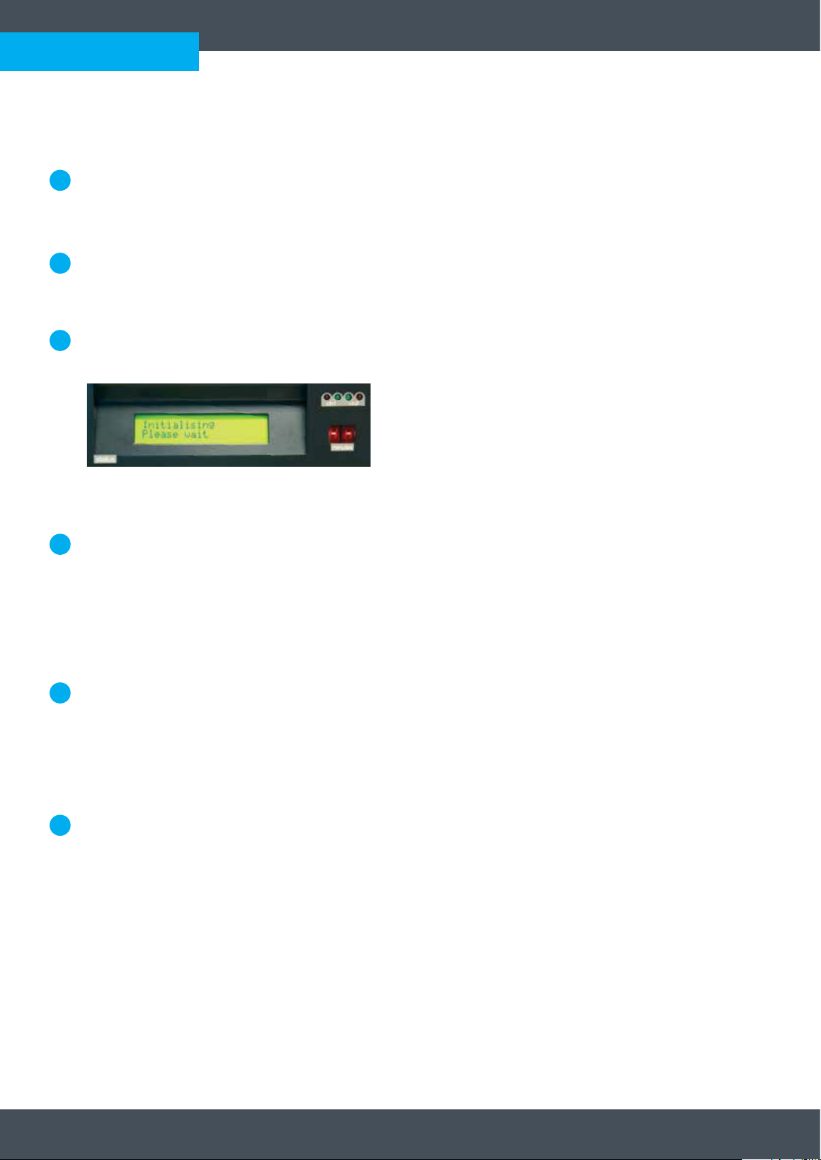
PEAK LEVEL INDICATORS
The two element peak reading LED meters, ch 1 and ch 2, monitor the input signal in the two audio channels.
The red LED indicates maximum allowable recording level.The green LED indicates a level approximately
20dB below this level. A normal recording should light the green LED but not the red LED.
MONITOR OUTPUT
The rear panel remote monitor output provides line outputs to allow the external monitoring of the
microphone signals on channel 1 and channel 2 only when the recorder is in the Record mode.
The front panel remote monitor LED is lit to show that extrenal monitoring is taking place.
SIGNAL ALARM
If signal level on either channel is less than 30dB below peak level for a continuous period of more than 60
seconds, the alarm sounds continuously.The alarm is silenced when the signal level is restored or the Record
mode is disengaged. (The Record mode is disengaged at end of disc or by selecting stop).
•A silent period of approximately 60 seconds is allowed after the start of any period of Record before the
alarm sounds.
•The signal alarm indicates microphone silence, microphone not connected, microphone cable
broken, or a fault in the recording chain of either channel.
Note: In some installations the sound of the alarm may be picked up by the microphone at a level
sufficient to light the green LED. If this is the case, the alarm indicates the lack of any normal recording
signal for a period of approximately 2 seconds, before the recording of the alarm sound silences the alarm.
The signal alarm indicates silence at the microphone, microphone not connected, microphone cable broken,
or a fault in the recording chain of either channel.
OPTIONAL CARRYING BAG
An optional carry bag is available for the 9102/9103.This provides protection for the recorder and storage
pockets for PSU, microphones and interview CDRs.

8
DATA FACILITIES
•The CD Recorder produces CDs to the CD-Extra format. Each CD contains both audio and data but still
conforms to the audio CD standard.
•If the CD is inserted into any media player (CD player, DVD player, windows media player etc) it will play
the Audio section of the CD.
•When the CD is inserted into a computer the Data section is made available.The computer may require
you to start your media player separately in order to play the audio section.
•The start time of the log file is the time at which the record button is pressed.
The start time of the audio file is the time at which the system actually commences making audio recordings.
There may be a difference between these two times of up to 15 seconds.
The finish time of both files is the time at which the stop button is pressed.
NORMAL OPERATING INDICATIONS
RECORD TIMER
The two digit minutes display indicates the period in minutes that Record has been selected on the discs.
The display is reset to 00 when the discs are inserted.

9102 & 9103
9
WHEN USING 9102/9103 WITH AN UNINTERRUPTIBLE
POWER SUPPLY (UPS)
If an uninterruptible power supply (UPS) is being used, the AC mains wall socket and the
recorder power switch should be left switched on at all times.
The recorder should be switched on and off using the UPS front panel power switch and the recorder front
panel power switch in the correct sequence.
The recorder should NOT be switched on and off by switching on and off the AC mains input.
HOW TO SWITCH THE RECORDER ON AND OFF
•To switch on, press and hold the UPS power switch until the UPS green LED lights.
•Then press the front panel power switch on the recorder and the recorder will power up.
•To switch off, press the front panel power switch on the recorder and wait for the recorder to power
down - blue power LED off and displays blanked.
•Then press and hold the UPS power switch until the UPS green LED is off.
If the AC mains fails during recording, the UPS alarm will sound intermittently and the green LED will flash. If
this happens, follow the instructions on the next page to stop recording and eject the discs as soon as possible.
Then power down the recorder by pressing the UPS power switch.
In normal use the battery in the UPS will remain trickle charged.
If the mains fails during recording and the UPS is required to power the recorder without AC mains supply,
then the UPS will require a minimum period of 6 hours for its battery to regain a full charge, in readiness for a
possible further mains failure.
If the AC mains input to the UPS is disconnected or switched off for a period of more than one month, the
UPS should be connected to the AC mains for a minimum period of 6 hours in order to keep its battery in
good condition.
The recorder should be switched off first using the UPS front panel power switch before
disconnecting or switching off the AC mains input.

10
FAULT ALARM INDICATIONS
When a disc reaches its end or the system develops a fault the alarm sounds continuously.
If more than one alarm is active, the various messages are presented and repeated in sequence.
NO RECORDING MEDIA
If any discs are absent when record is pressed, then the Record mode is not engaged
and the alarm sounds momentarily.
WRONG RECORDING MEDIA INSERTED
If any discs of an incompatabile format are present when record is pressed, then the Record mode is not
engaged and the alarm sounds momentarily.
PRE-RECORDED DISC INSERTED
If any discs already contain a recording when record is pressed, then the Record mode is not engaged and the
alarm sounds momentarily.
AUDIO SIGNAL ALARM
If an audio channel fails the alarm sounds until signal is restored. Once signal is restored then the alarm is silent.
If the audio signal fault remains, the alarm sounds continuously. Stop all recording to silence the alarm.
(See AUDIO FACILITIES section page 8)
END OF DISC ALARM
If a disc reaches its end, then the alarm sounds continuously. Press stop to silence the alarm.
FAULTY MEDIA
If any disc fails during the Record mode the alarm sounds every 10 seconds. Recording continues on the
remaining discs.
•Press stop to end all recording.The alarm now sounds every 30 seconds.
•Press eject to finalise and eject all successful disc or discs.
•Press eject again to retrieve the faulty disc or discs.
LOW DISC
When the discs reach the low disc point, the alarm sounds. The low disc point is approximately 2 minutes
before the end of the recording.

9102 & 9103
11
CONNECTIONS
Switch off the power to this equipment before making any connections to the
sockets on the rear of the equipment.
UNINTERRUPTIBLE POWER SUPPLY (UPS)
If not using an uninterruptible power supply, connect the in-line AC mains to DC adaptor to the recorder and
connect the mains adaptor to the AC mains supply using the power lead supplied, with13A plug to IEC figure-
of-eight mains socket (IEC 320 C7).
If using an uninterruptible power supply, connect the UPS input to the AC mains supply, and connect the mains
adaptor to the UPS output using power lead with IEC 3 pin mains plug (IEC 320 C14) to IEC figure-of-eight
mains socket (IEC 320 C7).
MICROPHONES
Connect the microphones to mic input ch 1 and mic input ch 2.
The connections to the 3 pin XLR plug of the microphone inputs are as follows:
input - pin 3
signal ground (at +3V) - pin 2
0V (ground) - pin 1
Use 2 core screened cable, with the screen connected to pin 1.
REMOTE MONITOR
The audio outputs from the rear panel remote monitor socket are only enabled when the recorder is in the
record mode and the remote monitor switch on an external remote monitor unit is closed (on).
The remote monitor enable switch may have an additional monitor indicator LED wired in series.
Whilst monitoring is enabled the front panel LED “remote monitor” will be illuminated.This remote monitoring
function is provided in accordance with legal guidelines for certain countries and applications.
The connections to the 5 pin 180˚ DIN plug are :
channel 1 - microphone signal - pin 1
channel 2 - microphone signal - pin 4
ground - pin 2
monitor enable (+12 volts) - pin 3
Use screened cable, with the screen connected to the shell of the DIN plug.

12
SAFETY NOTICE
The wires in the mains lead for the in-line power supply supplied with this apparatus are coloured in
accordance with the following code:
Blue = Neutral Brown = Live
If the mains plug needs to be removed and if the colours of the wires in the mains do not correspond with the
coloured markings identifying the terminals in your plug proceed as follows:
The wire which is coloured blue must be connected to the terminal which is marked with the letter N or is
coloured black.
The wire which is coloured brown must be connected to the terminal which is marked with the letter L or
coloured Red.
CONNECTIONS
Switch off the power to this equipment before making any connections to the sockets on the rear of the
equipment.
MALFUNCTION
In the event of any apparent malfunction in the operation of the equipment, first switch off, wait at least ten
seconds and switch on again. Contact service personnel if the malfunction remains.
LITHIUM BATTERY
This equipment includes a replaceable lithium battery.This should only be replaced by qualified service
personnel, noting the following:
CAUTION
Danger of explosion if battery is incorrectly replaced. Replace only with the
same or equivalent type recommended by the manufacturer. Dispose of used
batteries according to the manufacturer’s instructions.

9102 & 9103
13
QUICK GUIDE FOR 9102
Dual CD Recorder
•Switch On using the power button.
•Wait until status display continuously shows the time in the first row
and date in the second row:
•Check that the CD is a CD-R types.
•Insert CDs in the recorder with label facing up.
•Wait (approx. one minute) until the CDs have been accepted – each Ċsymbol in the status display
will then change to Ĉ(the disc present symbol):
•Press record. Wait until start alarm is silent before starting interview. During recording the date changes to
elapsed time after one minute. A typical status display is:
•At end of recording press stop. The display changes to:
•Press eject.Wait for CDs to Finalise and eject. (approx.Two minutes) The display shows:
•When the discs are being ejected the display shows:
•The discs will automatically be ejected
•Switch off the recorder by the front panel power switch.
alternating
with
alternating
with

14
QUICK GUIDE FOR 9103
Triple CD Recorder
•Switch On using the power button.
•Wait until status display continuously shows the time in the first row
and date in the second row:
•Check that the CD is a CD-R types.
•Insert CDs in the recorder with label facing up.
•Wait (approx. one minute) until the CDs have been accepted – each Ċsymbol in the status display
will then change to Ĉ(the disc present symbol):
•Press record. Wait until start alarm is silent before starting interview. During recording the date changes to
elapsed time after one minute. A typical status display is:
•At end of recording press stop. The display changes to:
•Press eject.Wait for CDs to Finalise and eject. (approx.Two minutes) The display shows:
•When the discs are being ejected the display shows:
•The discs will automatically be ejected
•Switch off the recorder by the front panel power switch.
alternating
with
alternating
with

9102 & 9103
15
TECHNICAL CONFIGURATION GUIDE
SET-UP
Operational parameters of the machine can be customised
within the set-up menu. Parameters set will be retained
even after the loss of power.
•To enter the set-up menu, access is via codes entered
using the record and stop keys whilst eject is pressed.
Menu code =27
•Hold down the eject key.
•Enter the first digit of the access code on the record key (press twice)
and the second digit on the stop key (press seven times)
•Each press counts up. Invalid access codes result in no response.
•Hold down eject key until display shows SETUP TOP LEVEL menu.
•Set-up menu items are displayed one at a time, as for example [MEDIA TYPE].
SELECTION OF MENU ITEMS
•On the set-up menu, use the record or stop key to scroll to the menu item of interest
•Press the eject key to enter the first item on this sub-menu.
•Further operations of the eject key select further items on this sub menu.
CHANGE OF PARAMETERS
•If a numeric field is flashing then it can be adjusted by increment or decrement.
•Press the stop button to increment. Press the record button to decrement.
STORING CONFIGURATION
Any change to a configuration setting is automatically stored by moving on to a display of a new sub menu item.
•When in sub-menu, return to the set-up menu by pressing eject when [EXIT] is shown on the bottom line
of the sub-menu.
•When in set-up menu, either press record or stop to select [exit] and press eject to exit from
configuration routine.
CONFIG.TIME AND DATE SUB MENU
Note: When changing the time and date ALWAYS check or change the TIME ZONE FIRST. The time zone has
a major effect on the time and therefore MUST be set prior to changing the time and date.
Set day of month: Press record to increment or press stop to decrement the day of the month then press
eject button.
Set month: Press record to increment or press stop to decrement the month then press eject button.
Set Year: Press record to increment or press stop to decrement the year then press eject button.
Set hour: Press record to increment or press stop to decrement the hour then press eject button.
Set minute: Press record to increment or press stop to decrement the minute.
Finally, press eject button.
The time now is set and you will be taken to the Top-Level Menu.
Scroll Up / Increment
Scroll Down
/ Decrement

16
TIME ZONE SUB MENU
Note: When changing the time and date ALWAYS check or change the TIME ZONE FIRST.The time zone has a
major effect on the time and therefore MUST be set prior to changing the time and date.
Set letter of country:
•Press record to increment through the alphabet until you reach the first letter of the country in the
required time zone. e.g. Increment to B for Britain.
•Press stop to decrement through the alphabet.
To exit to Top-Level menu cycle through to end of alphabet until [EXIT] then press eject button.
Set country:
•Press record to increment through the countries beginning with the letter you previously selected
until you reach the country in the required time zone.
•Press stop to decrement through the countries.
To exit to Top-Level menu cycle through to end of alphabet until [EXIT] then press eject.
Set city or area:
•Press record to increment through the time zones within the country previously selected.
This could be a city or an area.
•Press stop to decrement through the time zones with the country.
To exit to Top-Level menu cycle through to end of alphabet until [EXIT] then press eject.
Finally, press eject key:
This will confirm that the time zone will be altered. However a restart of the system is required.
CD-EXTRA SETUP SUB MENU
•Press eject key:‘XML Enabled’: Press record or stop key to select [ON] or [OFF] operation.
•DEFAULT is off.
Note: CD-EXTRA record enhanced meta data to the CD. This format is NOT valid for some transcription
software.When CD-EXTRA is enabled the finalisation time is approximately doubled.
•EXIT sub menu.
•Press eject key:This will save and exit from the configuration settings.

9102 & 9103
17
QUICK GUIDE FOR SETTINGTHETIME
STEP 1
•Press and hold the eject button for the duration of
this first step.
•Press the record button 2 times.
•Press the stop button 7 times until set ‘SETUP TOP
LEVEL’ appears on the LCD screen.
Use the record button to scroll up and the stop button
to scroll down through the menus.
STEP 2
•Scroll up until ‘CONFIG TIME AND DATE’ shows
in LCD display.
•Press the eject button to get into the TIME AND
DATE setting.
STEP 3
•Press the eject button until the digit that needs
changing is selected. It will flash when it is selected.
•Press record (scroll up) or stop button
(scroll down) to select the correct value.
STEP 4
•When the correct time is set, press the eject
button to come out of time set.
•Press the stop button once to take you to EXIT.
•Press the eject button to save the changes to
the recorder.
Scroll Up / Increment
Scroll Down
/ Decrement

18
NOTES

9102 & 9103
19
NOTES
This manual suits for next models
1
Table of contents