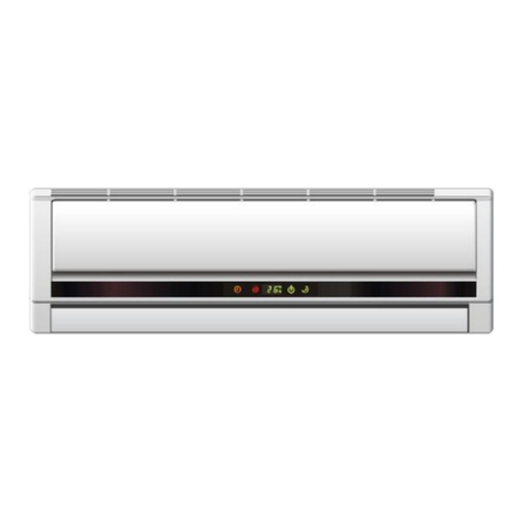
NEC NSC250F User manual

Thank you for choosing our Air Conditioner. Please read this OWNER'S
MANUAL carefully prior to use and keep it for further reference.
This owner's manual is applicable to those split wall mounted models
whose cooling capacity is between 2000W(7000BTU/h) and 7000W
(24000BTU/h).
SPLIT WALL MOUNTED TYPE
AIR CONDITIONERS OWNER'S MANUAL
NSC250F NSC330F NSC680F
NSR330F
NSR250F NSR680F
NSC510F

33
1212
Safety Awareness
Name of Parts
Service and Maintenance
Trouble Shooting
Performance Parameters
1313
55
22
CONTENTS
11
Contents
11
Operation of Remote Controller
88

PERFORMANCE PARAMETERS
1.The indicatednoise parameter ismeasured in laboratoriesbefore leaving factory.
NOTICE
2.The ratedcooling/heating capacity istested under thefollowing conditions:
Cooling operation
Heating operation
Indoor
Indoor
Outdoor
Outdoor
20 (DB)
35 (DB)
7 (DB)
19 (WB)
15 (WB)
24 (WB)
6 (WB)
5.Wiring diagram of air conditioner (indoor unit/outdoor unit) are attached to the indoor/ outdoor unit
respectively.
6.If the supply cord is damaged, it must be replaced by the manufacturer, its service agent or similarly
qualified persons in order to avoid a hazard.
27 (DB)
Maximum cooling Minimum cooling Maximum heating Minimum heating
Indoor side DB/WB( )
Outdoor side DB/WB( )
C
C
32/23 21/15 27/-- 20/--
43/26 21/15 24/18 -5/-6
3.Due tothe policy ofconstant development, wereserve the rightto modify technicaldata without
notice. While errorsand omissions area possibility, every reasonableeffort has been made to
ensure that theinformation in thismanual is correct.
4.Operating temperature range:
22
Rated cooling capacity(W)
Rated heating capacity(W)
Cool
Cool
Aux-heat
Aux-heat
Dehumidifying capacity (L/h)
Waterproof class
Noise(dB(A))
Net weight(kg)
Climate type
Power
Indoor
Outdoor
NSC250F
920
400
1.2
IP20(INDOOR) IP24(OUTDOOR)
I
T1
37
48
10
28
500x830x310
2800
4.2
3.9
400
1.2
3500
1300
1250
6.0
5.7
450
1.6
39
51
10
33
50
58
15
63
50
58
15
65
1280
6.1
460
1.6
2500
12.1
1100
3.3
2500
12.1
1100
3.3
38
47
10
30
39
48
10
31
920
890
Heat pump
Heat pump
Rated input
power(W)
Rated input
CURRENT(A)
Protection class
Dimension HxWxD
(mmxmmxmm)
Indoor
Outdoor
Outdoor
Indoor
Model
290x800x183 290x800x183
500x830x310
NSR250F NSC330F NSR330F NSC680F NSR680F
4.0
7500
2850
12.6
240V~, 50Hz
2500 2500 3500 3200 6600 6500
Air flow volume(m /h)
3
330x1080x220
850x870x365
Refrigerant(R22)charge amount(g)
500x830x310
290x800x183
500x830x310
290x800x183
330x1080x220
850x870x365
2050
9.3
750
43
55
14.5
49
NSC510F
5050
690x860x370
315x1020x178
2.5
720 1600
720 1100 800 2300 2350

Absolutely not Must be done
Do not damagethe power cord,or do jointwork. Piling up
heavy objects onthe power cable,approaching high
temperature supply objects,or doing jointwork will cause
Do not apply the cold air to the body for a long time. It will
deteriorate your physical conditions and cause health problems.
WARNING
The air conditioner must be grounded. Incomplete grounding
may result in electric shocks. Do not connect the earth wire
to the gas pipeline, water pipeline, lightning rod, or telephone
earth wire. After installment, earth leakage examination must
be carried on through electrifying.
Pull out the power plug or turn off the power supply when
not using the air conditioner for a long time. (Accumulated
dirt might cause fire.)
Read and understandthoroughly this safetyawareness before use.
Do not pullthe power cable duringoperation. It can cause
fire. To pull outthe plug, pleaseturn off theunit and hold
the plug topull it out.
Do not connect the wire from the middle of the power cable
or extend it. Do not use multi-hole sockets.
An earth leakagebreaker with rated capacity must be
installed to avoidpossible electric shocks.
SAFETY AWARENESS
The following picturesare presented justfor the purposeof illustration.As for somemodels whose
cooling capacity isabove 4600W(17000BTU/h), theirpower cables donot have aplug! So please
take real objectsas a reference.
The items indicatedhere are veryimportant safety precautions,which must befollowed.
electric shock andfire.
33

WARNING
Do not putburning appliances at places exposed to the
airflow, itmay cause incomplete combustion.
Stop operation and turn off the breaker immediately if anything
abnormal occurs (such as burning smell or smoke).
Close doors andwindows (preferably use a curtain) while
operating air conditionerfor a long time, if room air is quite
turbid, you couldopen the door and window for a moment
to get somefresh air outside.
Do not install the air conditioner at places where flammable
gas may leak. If there is electrical leakage accidentally from
air conditioner, it is easy to cause fire or explosion.
Do not apply the unit for special purposes. Do not use to store
precision equipment, food, painting etc, which require certain
humidity and temperature, for their quality may be affected.
Do not open windows and doors while operating the air
conditioner at COOL/DRY mode for a long time under high
humidity condition (above 80%). Otherwise, condensed
water may drip from the unit.
The appliance shallbe installed in accordance with national wiring regulations.
The appliance mustnot be installed in the laundry.
The appliance mustbe installed 2.3m above the floor.
The appliance mustbe positioned so that the plug is accessible.
For some modelswhose cooling capacity are above 4600W (17000BTU/h),
an all-pole disconnectiondevice which has at least 3mm separation distance in
all pole shallbe incorporated in the fixed wiring according to the national rule.
Do not insert a finger, a rod or any other objects into the air
outlet/inlet grille. As the fan is running at a high speed, it will
cause injury.
Clean the air conditioner with a piece of softand dry cloth.
Do not usethese stuffs for cleaning: chemical solvent,
insecticide, inflammable spraying materials which will
damage the appearance of air conditioner. Do notsprinkle
SAFETY AWARENESS
water directly onthe indoor unit.
44

Run indicator lamp
2.DISPLAY MODELS
INDICATOR LAMPS
A:A:
This illustration generalizes all thedisplays for themodels included inthis manual book.
Please take realobjects as referencewhile using.
SleepSleep
Run
Run
TimerTimer
Time indicator lamp
SleepSleep
RunRun
Timer
Timer
Time indicator lamp
“ ”ICON+INDICATOR LAMP
OROR
++
B:B:
Set temperature
and timer display
aabb
cc
1.OUTDOOR UNIT AND INDOOR UNIT
Connecting pipe
Drain hose
Air inlet
Air outlet
Drain opening
Appearance ofthe indoor unitand outdoor unitmay differ with some models.
NOTICE
NAME OF PARTS
Sleep indicator lamp
Run indicator lamp
Time indicator lamp
Run indicator lamp
Sleep indicator lamp
Time indicator lamp
Sleep indicator lamp
Remote signal receiver
Sleep indicator lamp
Run indicator lamp
Time indicator lamp
Sleep indicator lamp
Run indicator lamp
55
(Manual operation)
Left / Right deflector
Filter Air inlet
Deflector Display
Front panel

While using, only relevant icons will light up with their displays on.
C:LED WINDOWC:
Continuing research results in steady improvement. Therefore, This information
and these specifications are subject to change without notice.
Room temp
Cool mode Fan mode Auto mode
Setting temp and timer display
Sleep mode
Electric-heat mode
NAME OF PARTS
Fan speed display
Dry mode
Time mode
Heat pump mode
66
Cool mode
Fan mode
Electric -heat mode Heat pump mode
Sleep modeSet timer mode
Dry mode
Low fan mode Middle fan mode High fan mode
Light-wave mode
Setting temp andtimer display
Auto mode
Temperature display
a. Display on the right side of the indoor unit.
For the icon of LED windows, only relevant icons will light up with their displays on.
b. Display on the middle side of the indoor unit.
11
22
33

77
NAME OF PARTS
( ).
Check switch
Emergency
Operation switch
B.B.
C.C.
l(Cooling onlytype)
Every time theswitch is pressed, it changes in sequence of COOL STOP.
l(Heat pumptype)
Every time theswitch is pressed, it changes in sequence of COOL HEAT STOP.
The following table shows the condition of settemperature, fan speed and deflector during
emergency operation.
4.HORIZONTAL LOUVER BLADE
Hold the knob and move the deflector to change right/left airflow direction. Be careful not to adjust
the deflector during operation as the fan is rotating at a high speed and may pinch your fingers.
A.A.
3.EMERGENCY OPERATION SWITCH
In case thebatteries in theremote controller arewore out, orremote controller is at fault, use
Emergency operation switch
(Please leave this
button to beused
by the maintenance
staff)
Mode
Set temperature
Deflector
Fan speed
Swing
Swing
Heating
High
Cooling 24
C
24
C High

Cool only type has no HEAT mode.
SWING
MANUAL
OFF ON
CANCEL SET
SLEEP
FAN SPEED
OPERATION
MODE
I/O
TIME
MANUAL
SWING button
Signal ejecting window
SWING button
Press once, the setting
temperature increases by 1.
Press once, the setting
temperature decreases by 1.
The range of setting
temperature is 16-31 .
Press it to change the fan speed in
the order of low-medium -high-auto.
Press it to change up/down air flow direction
and the deflector automatically swings up
and down.
Press it to change up/down air flow direction
and the deflector moves at a certain angle.
you can change the moving angle in the order
of
(1) (2) (3) (4) (5)
Press it to select the operation mode.
ON TIMER button
OFF TIMER button
TIME SET button
Press it to fix the time setting.
TIME
CANCEL button
Press it to cancel the time setting.
Press it to start sleep running and
press again to stop it.
RESET pieces
If the remote controller can't work
normally, short two RESET pieces
with forceps, it will be OK.
Keep the remote controller within 6 metres in front of the indoor unit without any blockage.
If the air conditioner is not used for a long time, take the batteries out.
It sends signals to the indoor unit
Please see Timer operation
In this illustration, each section is shown with all its displays ON for the purpose of
explanation. Some models may not show all its indications.
TEMPERATURE
adjustment buttons
RUN/STOP button
OPERATION DISPLAY
FAN SPEED button
I t displays the current settings.
Press it once to start operation
and press again to stop it.
OPERATION
MODE button
COOL HEAT
FAN DRY
AUTO
SLEEP button
NOTICE:
REMOTE CONTROLLER
OPERATION OF REMOTE CONTROLLER
88

Timer operation
Timer must be set again after a power failure. otherwise, timer
operation is not right.
If you want to change the time after the setting time is fixed , you
should cancel the previous setting time by pressing button
and then set time again.
If you press the once incautiously after the setting
time is fixed, the setting time will automatically count time anew
automatically and the displayed time will not change.
button
Timer operation SET
Timer operation CANCELLATION
Press button
controller display.
when the air conditioner is off , of will
flicker on the remote
Press button or to enter time setting. Every pressing of
ON
emote controller display.will flicker on the r
while the air conditioner is operating , ofPress button
OFF
ON OFF
button or Increases the setting time by one hour and the
setting time will be displayed on remote controller.
Press button to fix the setting time. or will stop
flickering on the remote controller display.
SET
NOTICE
1.
2.
If you want timer operation cancelled, press button until the
setting time and or disappear on the remote
controller display.
¡±
¡±
OFF
3.
SET
1.
2.
3.
¡±
ON
CANCEL
CANCEL
99
OPERATION OF REMOTE CONTROLLER

In this mode, the air conditioner can automatically adjust the room
temperature to decide the most suitable temperature. At the start of
operation, the air conditioner will automatically select the operation mode
according to the room temperature. Please see the following table for
reference.(If you are not satisfied with the setting temperature decided by
the air conditioner, you can press TEMPERATURE ADJUSTMENT button
until the time setting reaches the point you like)
COOL mode
Press MANUAL SWING button or SWING button to change up/down
Press FAN SPEED button to change the fan speed of indoor unit.
Press TEMPERATURE ADJUSTMENT button to change the setting
temperature.
In this mode, the air conditioner automatically decides the setting
temperature and this setting temperature will not appear on display.
TEMPERATURE ADJUSTMENT button and FAN SPEED button don't
Press MANUAL SWING button or SWING button to change up/down air
or
or
Operation mode adjustment
AUTO mode
DRY mode
2.
3.
air flow direction.
work.
flow direction.
1.
Cool only type
Mode Initial Setting Temperature
Initial Setting Temperature
Mode
24
26
RT-2 RT-2
Cool Cool
Dry RT-2 RT-2
Dry
Heat
Heat pump type
24
C C
C
21
C
Room
Temperature (RT)
RT26
25 RT 23
RT23
26 RT 25
1010
OPERATION OF REMOTE CONTROLLER

5.
In this mode, the outdoor unit doesn't blow out wind. Wind is only blown
from the indoor unit. Press MANUAL SWING button or SWING button to
change up/down air flow direction.
Press FAN SPEED button to change the fan speed of indoor unit.
HEAT mode(heat pump type)
Press MANUAL SWING button or SWING button to change up/down air
flow direction.
Press FAN SPEED button to change the fan speed of indoor unit.
Press TEMPERATURE ADJUSTMENT button to change the setting
temperature.
¡±
A. The indoor fan runs at low speed.
B. One hour later, the setting temperature will automatically decrease by
2 and one hour later again, the setting temperature will automatically
decrease by 2 once more, then the air conditioner will keep running
at this final setting temperature.
C
¡±
6.
SLEEP mode
Sleep mode in heating running.
Sleep mode in cooling running.
A. The indoor fan runs at low speed.
B. One hour later, the setting temperature will automatically increase by
1 and one hour later again, the setting temperature will automatically
increase by 1 once more, then the air conditioner will keep running
at this final setting temperature.
C
C
C
or
or
4.
FAN mode or
1111
OPERATION OF REMOTE CONTROLLER

1.Open the front grille by pulling the tabs on both sides and liftit up until it stops with aclick.
Pull out the air filters.
2.Remove all dust on the front grille and air filters with avacuum cleaner or brush. (If the dust
does not come off easily, wash them with neutral detergent dissolved in warm water below
45 .)
3.Wash them in clean water and dry them inthe shade.
4.Insert the front grille and air filters at their original position and close the front grille.
5.Wipe the surface of the unit with aneutral detergent and then wipe it again with dry cloth.
(Be sure not to use benzene, solvent or other chemical products.)
Clean the front grille and air filters
If you will not be using the air conditioner for a long idle period
1.Set thefan going for a few hours to dry out the inside thoroughly. (Choose COOLmode or
HEAT mode and select the highest set temperature, then thefan rotates.)
2.Switch theair conditioner off and unplugit from thewall socket. Cleanthe filters andouter
surface.
3.Take out the batteries from theremote controller.
If you have not used the air conditioner for a long period
1.Clean filters andreplace them tothe original position.Clean the indoor and outdoor units with
a piece ofsoft cloth.
2.Insert thepower plug andmake sure theearth wire notbe loose.
3.Put thebatteries into theremote controller.
Air inlets andoutlets shall notbe covered/blocked.
For cleaning, donot use gasoline,benzene, thinner,grinding powder, detergent
insecticide etc asthey can damagethe units.
Don't tear thebatteries apart orthrow them intofire, which willlead to explosion.
FAN OPERATION
NOTICE
1212
SERVICE AND MAINTENANCE

Is there a fault? Fault analysis!
Air conditioner does
not operate.
Is it a power failure?
Has the power plug fallen off?
Has the circuit breaker or fuse shut off
Are there any obstacles or disturbance
supply oscillators in the room to disturb the
signal from remote controller?
Remote controller is
not available and
does not display.
Operation does not
start soon whenI/O
button is pressed
after operation was
stopped.
Cooling and heating
effect is not good.
Air will not
immediately blow
out at thestart of
HEAT mode.
The air conditioneris ready to blow out
enough warm air. Please wait.
This is a way toprotect the air conditioner.
Please wait 3 minutes.
Is temperature setting appropriate?
Are the air filters clean?
Are there any obstacles to block the inlets
and outlets of the indoor and outdoor units?
Is sleep mode used during daytime?
Is the indoor fan speed set low?
Are doors and windows closed?
The power supply may
be suddenly cut off,
when the power is
normal again; the air
conditioner will automatically
resume the same mode
operation as setting before
power failure.
This is called auto-restart function and this
function is only accessible for certain types of
air conditioners with the function of auto-restart.
Check whether the batteries of remote
controller are usable.
Check whether the batteries are positioned
correctly.
The following casesare not troublesthat will obstructyou in usingplease follow the fault analysis
and continue using.
1313
TROUBLE SHOOTING

Indoor unit fanstops
during heating.
The air conditioner is deicing and it takes
10 minutes at most.( It freezes when
outdoor temperature is low and humidity is
high). It automatically resumes operation
about 10 minutes later.
Issue cracking
sounds.
The friction sounds are caused by expansion
and contraction of front grille resulting from
temperature changes.
You can hear the
sound of running
water.
It is the sound of flowing refrigerant inside
the air conditioner.
Sound of accumulated flowing water on the
Heat-exchanger.
Sound of frost melting on the heat exchanger.
Indoor unit makes
“bush” sound and
click sound.
Click sound is made by the switching of the
fan or compressor.
“Bush” sound is made by the switch of
refrigerant flowing inside the air conditioner.
Indoor unit gives
out odor.
Air conditioner may have absorbed odors
from wall, carpet, furniture and again blows
out.
Outdoor unit leaks
water.
During cooling, connecting pipe or pipe
connector will cause the moisture content
condensation due to the low temperature.
During heating or defrosting, melting water
and water vapor will run out.
During heating, water on heat exchanger
will drop.
Is there a fault? Fault analysis
If you find one of the following symptoms, please turn the breaker off quickly and call our
designated service shop nearest to you for help.
The power cordis abnormally hotor damaged.
An abnormal soundis heard duringoperation.
The safety breaker, fuse or the earth leakage breaker often cutsoff the operation.
Some switch orbutton often failsto work normally.
The air conditionergives out burningsmell during operation.
Water leaks from the indoor unit.
1414
TROUBLE SHOOTING

NEC Australia Pty. Ltd.
ABN 86 001 217 527
Home Electronics Group
NEC Service Centres PH:131-632
New South Wales
Sydney 184 Milperra Rd, Revesby 2212 131-632
Newcastle 120 Parry Street, Newcastle West 2302 131-632
Victoria
Melbourne Unit 1/6 Garden Road, Clayton 3168 131-632
Queensland
Brisbane Unit 4 / 305 Montague Road, West End 4101 131-632
Southport Shop 1, 48 Ferry Road, Southport 4215 131-632
South Australia
Adelaide 84A Richmond Rd, Keswick, 5053 131-632
Western Australia
Perth 45 Sarich Court, Osborne Park 6017 131-632
For Service in outer areas, please contact your NEC retailer for the addr ess of
the nearest Authorised NEC Service Centre
NEC Australia Pty. Ltd.
Home Electronics Group
244 Beecroft Road EPPING 2121
Tel: 131 632
Fax: (02) 9877 2353
This manual suits for next models
6
Table of contents
Other NEC Air Conditioner manuals
Popular Air Conditioner manuals by other brands

Fujitsu
Fujitsu ASYG 09 LLCA installation manual

York
York HVHC 07-12DS Installation & owner's manual

Carrier
Carrier Fan Coil 42B Installation, operation and maintenance manual

intensity
intensity IDUFCI60KC-3 installation manual

Frigidaire
Frigidaire FAC064K7A2 Factory parts catalog

Sanyo
Sanyo KS2432 instruction manual

Mitsubishi Electric
Mitsubishi Electric PUHZ-RP50VHA4 Service manual

Panasonic
Panasonic CS-S18HKQ Service manual

Panasonic
Panasonic CS-E15NKE3 operating instructions

Gree
Gree GWH18TC-K3DNA1B/I Service manual

Friedrich
Friedrich ZoneAire Compact P08SA owner's manual

Daikin
Daikin R32 Split Series installation manual