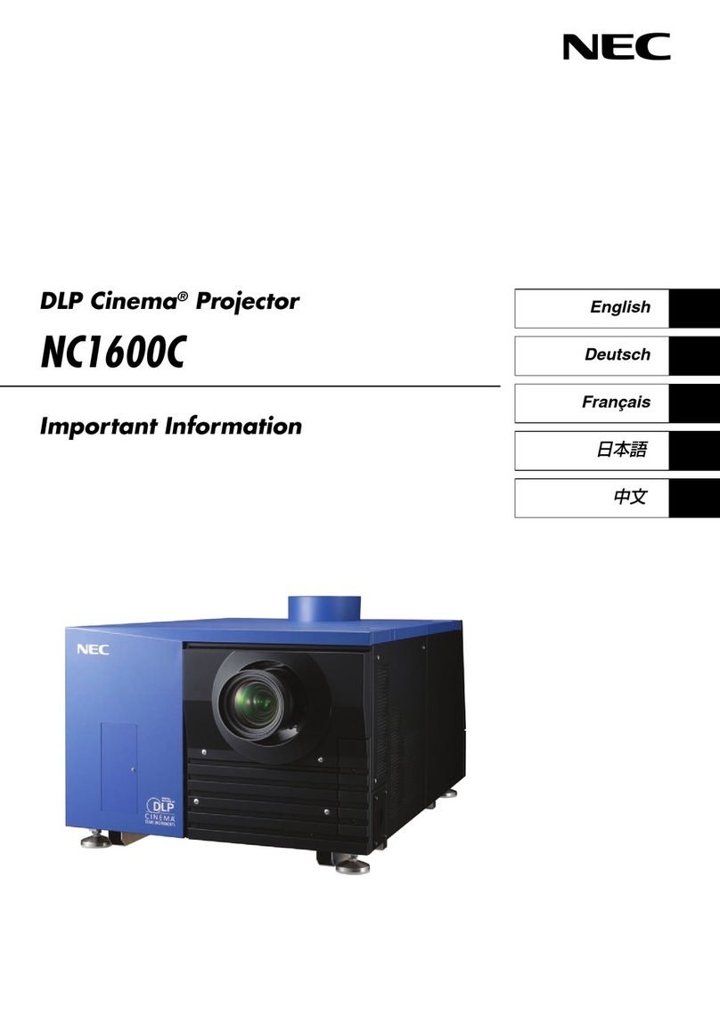
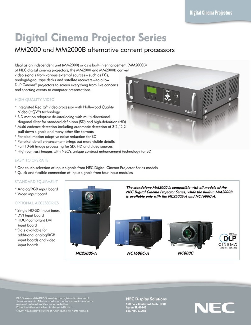
NEC NP-NC900C-A User manual

SAFETY CAUTION:
Before servicing this chassis, it is important that the service
technician read and follow the “Safety Precautions” and “Product
Safety Notice” in this Service Manual.
WARNING:
SHOCK HAZARD - Use an isolation transformer when servicing.
PART No. 3N9911183 (3rd Edition)
DLP Cinema®Projector
SERVICE MANUAL
Better Service
Better Reputation
Better Prot
MODEL NP-NC900C-A
NP-NC900C-A+
NEC DISPLAY SOLUTIONS, LTD.
Copyright Contents 1. Safety precautions
2. Spacications 3. User's Manual 4. Troubleshooting
5. Key part replacement
(Method of disassembly/Photo taken from life)
6.
Method of disassembly
(Illustration/Photo taken from life)
7. Disassembly
(IllustrationPhoto taken from life)
8. Adjustment matrix 9. Program setting and
software download 10. Setting & adjustment
11. Circuit description 12. Part list 13. Block diagram
Back cover

(1) Copyright (C) NEC Display Solutions, Ltd.
All Rights Reserved.
Thisdocumentcontainscondentialinformation.
Unauthorized copying, duplication, distribution, or
republication is strictly prohibited.
(2) Thecontentsofthismanualaresubjecttochange
without prior notice.

CONTENTS
SAFETY PRECAUTIONS ................................................................................................................................... 1-1
SPECIFICATIONS ............................................................................................................................................. 2-1
Fan Location................................................................................................................................................... 2-2
User's Manual .................................................................................................................................................... 3-1
TROUBLESHOOTING........................................................................................................................................ 4-1
RS-232 Protocol Command & System Flow .................................................................................................. 4-1
Troubleshooting & Error Code........................................................................................................................ 4-7
Connection Diagrams Troubleshooting ........................................................................................................ 4-15
Troubleshooting when start-up failure occurred ........................................................................................... 4-33
Troubleshooting when output video is abnormal.......................................................................................... 4-34
FAN layout.................................................................................................................................................... 4-35
Error Code List ............................................................................................................................................. 4-36
ICP_LEDs..................................................................................................................................................... 4-41
KEY PART REPLACEMENT (Method of disassembly/Photo taken from life) .............................................. 5-1
METHOD OF DISASSEMBLY (Illustration/Photo taken from life).................................................................. 6-1
DISASSEMBLY (Illustration/Photo taken from life) ........................................................................................ 7-1
ADJUSTMENT MATRIX ..................................................................................................................................... 8-1
PROGRAM SETTING AND SOFTWARE DOWNLOAD .................................................................................... 9-1
ICP Board Software Download ...................................................................................................................... 9-1
Slave MCU Board Software Download .......................................................................................................... 9-4
Full Auto Software Download ........................................................................................................................ 9-6
Motor Board Software Download ..................................................................................................................9-11
SETTING & ADJUSTMENT .............................................................................................................................. 10-1
Motor Board Setting and Adjust.................................................................................................................... 10-1
Color Band Adjust ........................................................................................................................................ 10-8
Color Calibration Adjust.............................................................................................................................. 10-10
Focus Adjust............................................................................................................................................... 10-14
CIRCUIT DESCRIPTION ...................................................................................................................................11-1
CPU PWB Circuit Operation..........................................................................................................................11-1
MOTOR PWB Circuit Operation ...................................................................................................................11-5
PART LIST ........................................................................................................................................................ 12-1
NP-NC900C-A.............................................................................................................................................. 12-1
NP-NC900C-A+............................................................................................................................................ 12-9
BLOCK DIAGRAM............................................................................................................................................ 13-1

SAFETY PRECAUTIONS
1-1
CAUTION
RISK OF ELECTRIC SHOCK
DO NOT OPEN
CAUTION: TO REDUCE THE RISK OF ELECTRIC SHOCK, DO NOT REMOVE
COVER. NO USER-SERVICEABLE PARTS INSIDE. REFER SERVICING
TO QUALIFIED SERVICE PERSONNEL.
This symbol warns the user that uninsulated voltage within the unit
may have sufficient magnitude to cause electric shock. Therefore, it is
dangerous to make any kind of contact with any part inside of this unit.
This symbol alerts the user that important literature concerning the
operation and maintenance of this unit has been included.
Therefore, it should be read carefully in order to avoid any problems.
ATTENTION
RISQUE D'ELECTROCUTION
NE PAS OUVRIR
MISE EN GARDE: AFIN DE REDUIRE LES RISQUES D' ELECTROCUTION, NE
PAS DEPOSER LE COUVERCLE, IL N'Y A AUCUNE PIECE
UTILISABLE A L'INTERIEUR DE CET APPAREIL. NE CONFIER
LES TRAVAUX D'ENTRETIEN QU'A UN PERSONNEL QUALIFIE.
Ce symbole a pour but de prévenir I' utilisateur de la présence d'
une tension dangereuse, non isolée se trouvant à l' intérieur de l'
appareil. Elle est d' une intensité sufsante pour constituer un risque
d' électrocution. Eviter le contact avec les pièces à l' intérieur de cet
appareil.
Ce symbole a pour but de prévenir l' utilisateur de la présence d'
importantes instructions concernant l' entretien et le fonctionnement de
cet appareil. Par conséquent, elles doivent être lues attentivement an
d' éviter des problèmes.
WARNING
HEATSINK MAY BE ENERGIZED.
TEST BEFORE TOUCHING.
Heat sink located on the power board, is electried.
mark is putted on the primary heat sink.
Pay attention to this area.

1-2
SAFETY PRECAUTIONS
During servicing carefully observe the following.
1. OBSERVE ALL PRECAUTIONS
Items and locations that require special care during
serv-icing, such as the cabinet, chassis, and parts are
labelled with individual safety instructions. Carefully
comply with these instructions and all precautions in
the instruction manual.
2. BE CAREFUL OF ELECTRIC SHOCK
The chassis carries an AC voltage. If you touch the
chassis while it is still alive, you will get a severe
shock. If you think the chassis is alive, use an isolating
transformer or gloves, or pull out the plug before
replacing any parts.
3. USE SPECIFIED PARTS
The components have been chosen for minimum
ammability and for specic levels of resistance value
and withstand voltage. Replacement parts must
match these original specifications. Parts whose
specifications are particularly vital to safe use and
maintenance of the set are marked on the circuit
diagrams and parts list.
Substitution of these parts can be dangerous for you
and the customer, so use only specied parts.
4. REMOUNT ALL PARTS AND RECONNECT ALL
WIRES AS ORIGINALLY INSTALLED
For safety, insulating tape and tubes are used
throughout, but some lift-off parts on the printed wiring
board require special attention.
All wires are positioned away from high-temperature
and high-voltage parts, and, if removed for servicing,
they must be retuned precisely to their original
positions.
5. LAMP
Be very careful of the lamp because it generates high
heat while it is used at high voltage. When replacing
the bulb, make sure it is cool enough.
6. LENS
Do not look into the lens during projection. This
important to avoid damage to the eyes.
7. SERVICING
At the time of repair or inspection services, use an
earth band (wrist band), without fail.
8. RUN A COMPLETE SAFETY CHECK AT THE
COMPLETION OF SERVICING
After comp le ti on o f se rvicing , co nf ir m th at a ll
screws, parts, and wiring, removed or disconnected
for servicing, have been returned to their original
positions. Also examine if the serviced sections and
peripheral areas have suffered from any deterioration
as a result of servicing. In addition, check insulation
between external metallic parts and blades of wall-
outlet plugs. This examination is indispensable in
conrming complete establishment of safety.
(Insulation check)
Pull out a plug from a wall outlet to disconnect the
connection cable. Then turn on the POWER switch.
Use a 500V megger (Note 2) and confirm that the
insulation resistance is 1MΩ or more between each
terminal of the plug and exposed external metal (Note
1). If the measured value is below the specied level,
then it is necessary to inspect and x the set.
(Note 1)
Exposed external metal....RGB input terminals, control
terminals, etc.
(Note 2)
If a 500V megger is not available for an unavoidable
reason, then use a circuit tester or the like for inspection.

MAINTENANCE
1. Cleaning the projector
1-1 Cleaning the Cabinet
Refer to the following guide to clean the projector cabinet.
a. Wipe off dust with a clean dampened cloth.
b. Moisten the cloth with warm water and mild detergent and wipe the cabinet.
c. Rinse all detergent from the cloth and wipe the projector again.
CAUTION
To prevent discoloration or fading of the case, do not use abrasive alcohol-based cleaners.
1-2 Cleaning the Lens
Refer to the following guide to clean the projector lens.
a. Apply a little optic lens cleaner to a clean, lint free cloth (do not apply the cleaner directly to the
lens).
b. Lightly wipe the lens in a circular motion.
CAUTION
Do not use abrasive cleaners or solvents.
To prevent discoloration or fading, avoid getting cleaner on the projector case.
1-3 Cleaning the Filters
The projector uses two lters to keep the fans free of dust and other particles, and should be cleaned every
500 hours of operation. In dustier environments, it is recommended to clean the lters more frequently. If
the lter is dirty or clogged, your projector may overheat. When the message below is displayed the lters
must be cleaned.
Please clean lter.
Note:
When the Please clean lter message is displayed, please clean or replace all two lters at the same
time to synchronize the hours used display.
The Filter Message item should be enabled in the Options menu.
1-3
SAFETY PRECAUTIONS

2-1
“Condential, Do Not Duplicate without written authorization from NEC.”
SPECIFICATIONS
1. SPECIFICATIONS
This section provides technical information about the projector's performance.
1-1 Specications
Model Name NP-NC900C-A
Projection method
3 chip DLP Cinema ® method
0.69-inch DC2K chip
Panel resolution 2048 x 1080
Lamp type 350W AC lamp
Screen sizes 7m to 8.1 m @14ft-L/Screen Gain 1.3, Max. 9.5m @14ft-L/Screen Gain 1.8 (Depends on
setup conditions)
Contrast ratio 1600: 1 with DCI specied color representation
Lens adjustment function Motorized lens shift (vertical/horizontal), motorized zoom, motorized focus, douser
Signal input ports When shipped from factory. Empty
(for mounting optional components) (Note 1)
External Control
RS-232C (D-sub 9pin) x1
GPIO port (D-sub 37 pin) x1
Service terminal (stereo mini jack) x1
3D CTL (D-sub 15 pin) x1
USB (Type A) x1
Interlock port x1
Ethernet port (G-bit RJ-45) x1
Power supply voltage AC 100 to 120V, 50/60Hz signal phase
AC 200 to 240V, 50/60Hz signal phase
Input current 10.3 to 7.9 A (100 to 130 V)
5.1 to 4.3 A (200 to 240 V)
Power consumption 1023 W (100 to 130 V)
985 W (200 to 240 V)
Cooling method Cooling air system (Includes dust lter)
Noise level Less than 52 dB
Installation Orientation: Desktop/front, Desktop/rear, Ceiling/front, Ceiling/rear
Net weight 44 kg (Excluding lens)
Dimensions 621mm (W) x 798mm (D) x314mm (H) (Does not include protruding portions,
Includes foot.)
Environment
Operating temperature: 10 to 35°C
Operating humidity: 10 to 85% (non-condensing)
Storage temperature: –10 to 50°C
Storage humidity: 10 to 85% (non-condensing)
Operating altitude: 0 to 3000m/9800 feet (1600m/5500 feet to 3000m/9800 feet:
Set “Fan Speed Mode” to “High Altitude”)

2-2
“Condential, Do Not Duplicate without written authorization from NEC.”
SPECIFICATIONS
1-2 Fan Location
FAN No. FAN PART No. (TYPE) CONNECTOR LOCATION
FAN1 79TY1171(AFB1212H-SM09) FAN D-4P FIP inlet (DMD R)
FAN2 79TY1201(AFB-0612HC-F00) FAN C-6P DMD B
FAN3 79TY1221(AFB0712VHE-F00) CTL 5P PRISM
FAN5 79TY1121(AFB0512VHD-F00) FAN D-5P ROD-FRONT(LAMP 1)
FAN4 79TY1131(AFB0512VHD-F00) FAN D-6P ROD-REAR (LAMP 2)
FAN6 79GP1121(AFB1212H-SM09) FAN C-4P PRISM+SYSTEM-OUT
FAN7 79TM1351(AFB1212H-SM09) FAN E-3P LAMP IN
FAN8 79TM1351(AFB1212H-SM09) FAN C-3P LAMP-OUT
FAN9 79TM1311(BFB0712HD-SP01) FAN B-4P LAMP 2-BURNER
FAN10 79TM1321(BFB0712HD-SP01) FAN B-5P LAMP 1-BURNER
FAN11 79TY1211(BFB0712LD-SE01) FAN P-6P FOR FAN 8
FAN12 79GP1121(AFB1212H-SM09) FAN E-4P POWER IN
FAN13 79TY1161(AFB1212H-SM09) FAN E-5P POWER IN
FAN14 79TY1141(AFB1212HHE-CF00) CTL 3P NEC MUDULE OUT
FAN15 79TY1191(AFB-0612HC-F00) FAN D-3P DMD R
FAN16 79TY1151(AFB1212H-SM09) FAN E-5P POWER IN
ICP FAN 79TY1181(EFB0512HA-F00) On CPU Board

2-3
“Condential, Do Not Duplicate without written authorization from NEC.”
SPECIFICATIONS
Stand by
After cooling T = 90s
blower = X rpmblower = X rpm
Lamp delay cooling 20s
Turn on lamp
Turn on system
Stand by
0
No Pre-cooling
of blower
stop blower 30s
Avoid condensing
Turn off or
temperature ptotection
Normal condition to turn on lamp.
Fan9/Fan10 operation.
Two worse cases to turn on lamp.
Fan9/Fan10 operation.
Not lit in the end.
1. Delay Cooling for normal situation is 20s; for abnormal (AC off) is 20s; for lamp mode switch from single
lamp to dual lamp is 20s
2. For system fan: After cooling is 90s for all sysytem fans except fan9 and Fan10 (Fan tables of After
Cooling follow the last operating status.)
3. For lamp blower. After cooling blower stop 30s when the lamp be switched off. After 30s blower restart
and continue cooling for 60s.
4. Lamp mode switch from Dual lamp to Lamp1 only, Fan10 stop running right away and follow lamp
blower rule of after cooling. Then, stop the blower.
from Dual lamp to Lamp2 only, Fan9 stop running right away and follow lamp blower rule of after
cooling. Then, stop the blower.
(please lock lamp mode switch function for 90s)
count = 2count = 3count = 1count = 0
failed ignition
Avoid condensing
10s
Interrupt AC then
instant turn on lamp
10s 10s
turn on lampturn on lamp
30s 30s
show lamp
error msg
30s
failed ignition failed ignition

2-4
“Condential, Do Not Duplicate without written authorization from NEC.”
SPECIFICATIONS
succeeded ignition at 4th time.
count = 0count = 1count = 2
failed ignition
failed ignition delay cooling 20s
succeeded ignition
Avoid condensing
Interrupt AC then
instant turn on lamp
turn on lamp
10s 10s 10s 10s30s
30s
turn on lamp

4-1
TROUBLESHOOTING
“Condential, Do Not Duplicate without written authorization from NEC.”
1. TROUBLESHOOTING
1-1. RS-232 Protocol Command & System Flow
Use Tera Term as RS232 console
Set up the serial port of tera Term with the menu item “Setup/Serial Port…” as gure 1. Here, the Port eld is, for
example, COM4 which is the corresponding RS232 port connecting to the slave MCU.
Figure 1: Serial port setting of Tera Term
Setup the terminal of Tera Term with menu item “Setup/Terminal…” as gure 2.
Figure 2: Terminal setting of Tera Term

4-2
TROUBLESHOOTING
“Condential, Do Not Duplicate without written authorization from NEC.”
Use Tera Term to log message
Tera Term provides a way to log messages of RS232 console with time stamp included. Execute menu item “File/
Log…” of Tera Term, check plain text and time stamp in the option box as gure 3.
Figure 3: Message log setting of Tera Term
** RS-232 Retrieve Error Code Comment
Step1. Connect RS-232, and enter RS-232 comment interface.
Key in “op demsg = 1”, then system will feedback “OP DEMSG = 1”.
Step2. Next, key in “op r_err”, and then it will show 3 error codes.
And, the rst error code will be the current root cause of defective symptom.

4-3
TROUBLESHOOTING
“Condential, Do Not Duplicate without written authorization from NEC.”
The Main Flow Chart of Slave MCU
Notes:
- The Slave MCU will always running the main loop after the Master assert the MPWR+ signal, the Slave MCU
should not stuck in any error state.
- If Slave MCU detected any system error,
- The Slave MCU asserts the ALERT signal.
- The Master should send query command to Slave to get error code back.
- The Slave MCU waiting Master’s instruction to execute following operation.
Slave MCU
Start
Slave MCU Boot Up
Initialize processes
Does projector in
power on state?
System Monitoring Processes
(Monitor all of the Fans status,
Thermal management, CW-Cover
detection, Bi-Metal detection etc)
UART Command Processes
- Parse command from receive buffer.
- Execute command.
- The Slave MCU assert ALERT signal
to Master.
- The Slave MCU should ready current
error information for Master to query.
- Parse command
The Slave MCU will send ACK back to Master if received
command is legul, or send NAK if received command is ilegal.
(Detected system error)
(main loop)
- The Slave MCU perform the necessary initial setting and
control, ex: GPIO initial control, set timer, UART etc.
The Power ON state means the Slave MCU has got the
“Power ON” command from Mater and has executed the
Power ON processes, otherwise the Slave MCU is stay in
“Normal Standby”.
The Slave MCU will start here by below condition:
1. When Master assert the MPWR + signal.
2. When MPWR + has asserted and Master assert
RESET signal, the Slave MCU will restart.
N
(Normal
Standby
Mode)
Y
(Power ON Mode)

4-4
TROUBLESHOOTING
“Condential, Do Not Duplicate without written authorization from NEC.”
System Monitoring Processes
System Safety Monitoring
Other Possible Failure:
-Extended GPIO control failure
-Lamp init failure
-Lamp ignition failure
-Ballast communication failure
-Fan init failure (may caused by I2C
bus issue)
-I2C communication failure
System Monitoring
Thermal Management
FAN Control
Thermal Monitoring
Reserve
Reserve
Reserve
Lamp Interlock Detection
Lamp Door Detection
Slave MCU will assert the
ALERT signal to inform
Master if has any failure
be detected.
Lamp Thermostat Detection
Notch Filter Detection

4-5
TROUBLESHOOTING
“Condential, Do Not Duplicate without written authorization from NEC.”
Process pre-caution and error sequence:
Process Power off and Lamp off only Sequence:
CPU PWBSlave uC PWB
Update Pre-caution bits
and Notify
CPU PWB Slave uC PWB

4-6
TROUBLESHOOTING
“Condential, Do Not Duplicate without written authorization from NEC.”
Process AC-ON, Lamp Control Sequence:
C
B
D
A
AC_ON
Release Reset
Set Lamp on
Wait 3s
Get Response
Retry?
State =
Stand by?
Every 5s Check
if Timer > 90s then
reset slave MCU
Pre-cooling
?
Count
> 10? Lamp mode
- off?
Power
Button?
Error Fin
Lamp
Lit?
D
E
E
A
N
N
N
N
N
N
N
Y
Y
Y
Y
Y
Y
C
B

4-7
TROUBLESHOOTING
“Condential, Do Not Duplicate without written authorization from NEC.”
1-2. Troubleshooting & Error Code
Error Code Denition
In Delta RS232 debug mode, the slave MCU will response with error code in case of system error like lamp fail,
or thermal situation failure, etc. They are dened as below table.
System error codes were dened as following tables
Byte 0 Denition Byte 1 Denition
Bit 0 ErrMsgOverTempInlet Bit 0 ErrMsgFan1RotateError
Bit 1 ErrMsgOverTempDMD Bit 1 ErrMsgFan2RotateError
Bit 2 ErrMsgOverTempLamp Bit 2 ErrMsgFan3RotateError
Bit 3 Reserved Bit 3 ErrMsgFan4RotateError
Bit 4 ErrMsgOverTempBallast1 Bit 4 ErrMsgFan5RotateError
Bit 5 ErrMsgOverTempBallast2 Bit 5 ErrMsgFan6RotateError
Bit 6 ErrMsgInletSensorError [5] Bit 6 ErrMsgFan7RotateError
Bit 7 ErrMsgInDMDSensorError Bit 7 ErrMsgFan8RotateError
Byte 2 Denition Byte 3 Denition
Bit 0 ErrMsgFan9RotateError Bit 0 ErrMsgInterLockOpen
Bit 1 ErrMsgFan10RotateError Bit 1 ErrMsgSystemI2cFail
Bit 2 ErrMsgFan11RotateError Bit 2 ErrMsgEepromFail
Bit 3 ErrMsgFan12RotateError Bit 3 Reserved
Bit 4 ErrMsgFan13RotateError Bit 4 Reserved
Bit 5 ErrMsgFan14RotateError Bit 5 ErrMsgLampDoorOpen [5]
Bit 6 ErrMsgFan15RotateError Bit 6 Reserved
Bit 7 ErrMsgFan16RotateError Bit 7 ErrMsgSoftwareI2cFail
Byte 4 Denition Byte 5 Denition
Bit 0 ErrMsgPreCooling Bit 0 ErrMsgFan1DriverError
Bit 1 ErrMsgLamp1DoorOpen [5] Bit 1 ErrMsgFan2DriverError
Bit 2 ErrMsgLamp2DoorOpen [5] Bit 2 ErrMsgFan3DriverError
Bit 3 ErrMsg12VOverSpec[7] Bit 3 ErrMsgFan4DriverError
Bit 4 ErrMsgBallast1UartError Bit 4 ErrMsgFan5DriverError
Bit 5 ErrMsgBallast2UartError Bit 5 ErrMsgFan6DriverError
Bit 6 ErrMsgFanInitError Bit 6 ErrMsgFan7DriverError
Bit 7 ErrMsgExGpioFail Bit 7 ErrMsgFan8DriverError

4-8
TROUBLESHOOTING
“Condential, Do Not Duplicate without written authorization from NEC.”
[1] Detect rule:
Error Code Message – Troubleshooting and what parts need to replace
ErrMsgOverTempInlet
When Inlet temp > 45 in stand by mode or
Force ECO mode toggle and Inlet temp > 43 continue 5 mins
Temp. is over spec. Check if there is anything blocks in inlet or replace Inlet thermal sensor.
ErrMsgOverTempDMD
When DMD temp > 70 in stand by mode or
Force ECO mode toggle and DMD temp > 70 continue 5 mins
Temp. is over spec. Check or replace DMD thermal sensor.
ErrMsgOverTempLamp
Thermal Break toggle and Polling time is 500ms.
Check or replace Lamp thermal break.
ErrMsgOverTempBallast1
When Blaster temp > 90 in stand by mode or
Force ECO mode toggle and Blaster temp > 90 continue 5 mins
Check or replace Ballast1 thermal break.
Byte 6 Denition Byte 7 Denition
Bit 0 ErrMsgFan9DriverError Bit 0 ErrMsgNotchFilterOpen [5]
Bit 1 ErrMsgFan10DriverError Bit 1 Reserved
Bit 2 ErrMsgFan11DriverError Bit 2 Reserved
Bit 3 ErrMsgFan12DriverError Bit 3 Reserved
Bit 4 ErrMsgFan13DriverError Bit 4 Reserved
Bit 5 ErrMsgFan14DriverError Bit 5 Reserved
Bit 6 ErrMsgFan15DriverError Bit 6 Reserved
Bit 7 ErrMsgFan16DriverError Bit 7 Reserved

4-9
TROUBLESHOOTING
“Condential, Do Not Duplicate without written authorization from NEC.”
ErrMsgOverTempBallast2
When Blaster temp > 90 in stand by mode or
Force ECO mode toggle and Blaster temp > 90 continue 5 mins
Check or replace Ballast2 thermal break.
ErrMsgInletSensorError
When Inlet Sensor read value = -20 or Inlet Sensor loss connect.
Check or replace Inlet thermal sensor.
ErrMsgInDMDSensorError
When DMD Sensor read value = -20 or Inlet Sensor loss connect.
Check or replace DMD thermal sensor.
ErrMsgFan1RotateError - Fan1 gets error during projector working. Check and replace fan 1
ErrMsgFan2RotateError - Fan2 gets error during projector working. Check and replace fan 2
ErrMsgFan3RotateError - Fan3 gets error during projector working. Check and replace fan 3
ErrMsgFan4RotateError - Fan4 gets error during projector working. Check and replace fan 4
ErrMsgFan5RotateError - Fan5 gets error during projector working. Check and replace fan 5
ErrMsgFan6RotateError - Fan6 gets error during projector working. Check and replace fan 6
ErrMsgFan7RotateError - Fan7 gets error during projector working. Check and replace fan 7
ErrMsgFan8RotateError - Fan8 gets error during projector working. Check and replace fan 8
ErrMsgFan9RotateError - Fan9 gets error during projector working. Check and replace fan 9
ErrMsgFan10RotateError-Fan10 gets error during projector working. Check and replace fan 10
ErrMsgFan11RotateError-Fan11 gets error during projector working. Check and replace fan 11
ErrMsgFan12RotateError-Fan12 gets error during projector working. Check and replace fan 12
ErrMsgFan13RotateError-Fan13 gets error during projector working. Check and replace fan 13
ErrMsgFan14RotateError-Fan14 gets error during projector working. Check and replace fan 14
ErrMsgFan15RotateError-Fan15 gets error during projector working. Check and replace fan 15
ErrMsgFan16RotateError-Fan16 gets error during projector working. Check and replace fan 16
When FanX speed < Target speed 80% keep 15 seconds.

4-10
TROUBLESHOOTING
“Condential, Do Not Duplicate without written authorization from NEC.”
ErrMsgInterLockOpen
Inter Lock Open toggle and Polling time is 500ms.
Check if connectors are unplugged from slave board to interlock board or replace slave board and interlock
board.
ErrMsgSystemI2cFail
Read Exter IO fail and Polling time is 500ms.
Check or replace slave board.
ErrMsgEepromFail
When read EEPROM fail in system initial.
Check or replace slave board.
ErrMsgLampDoorOpen
Lamp Door (1 or 2) Open toggle and Polling time is 500ms.
Check the lamp1 & Lamp2 door.
ErrMsgSoftwareI2cFail
It’s blaster UART Fail
Check or replace slave board.
ErrMsgPreCooling
When fan initial fail in pre-cooling mode.
Check or replace all Fan Driver boards and Fans.
ErrMsgLamp1DoorOpen
When Lamp Door 1 Open toggle and Polling time is 500ms.
Check the lamp1 door.
ErrMsgLamp2DoorOpen
When Lamp Door 2 Open toggle and Polling time is 500ms.
Check the Lamp2 door.
This manual suits for next models
1
Table of contents
Other NEC Projector manuals

NEC
NEC NP-L50W User manual

NEC
NEC PA600X Series User manual

NEC
NEC GT950 - MultiSync XGA LCD Projector User manual

NEC
NEC PA621U User manual

NEC
NEC NC1100L-A User manual

NEC
NEC TriDigital HD4K User manual

NEC
NEC MultiSync MT1055 Installation and user guide

NEC
NEC NP-UM330W Series User manual

NEC
NEC L50W LED User manual

NEC
NEC MultiSync MT810 User manual

NEC
NEC NP4000 User manual

NEC
NEC PA803UL User manual

NEC
NEC NP-PA600 Series User manual

NEC
NEC NP216 Series User manual

NEC
NEC LT75Z - MultiSync SVGA DLP Projector User manual

NEC
NEC LT260 Series User manual

NEC
NEC NP1250 Series User manual

NEC
NEC VT460 User manual

NEC
NEC NP-PH1400U User manual

NEC
NEC MultiSync VT540JK User manual