NED XCM8040SAT8 User manual
User’s Manual
Provisional edition
Line Scan Camera
Type:XCM8040SAT8
NIPPON ELECTRO-SENSORY DEVICES CORPORATION

NED
8040SAT8 UME-0005-01
2
Introduction
Thank you for purchasing NED’s Line Scan Camera. We look forward to your
continued custom in the future.
For safety use
For your protection, please read these safety instructions completely before
operating the product and keep this manual for future reference.
The following symbols appear next to important information regarding safe
product handling.
Warning If the product is not handled properly, this may result in
serious injury or possible death.
Caution If the product is not handled properly, this may result in
physical injury or cause property damage.
Safety precaution
Warning
Never disassemble or modify this product, unless otherwise specified to do so
in this manual.
When hands are wet, avoid handling this product and do not touch any of the
connection cable pins or other metallic components.
Do not operate this product in an environment that is exposed to rain or other
severe external elements, hazardous gases or chemicals.
If the product is not to be used for an extended period of time, as a safety
precaution, always unplug the connection cable from the camera unit.
If the product installation or inspection must be executed in an overhead
location, please take the necessary measures to prevent the camera unit and
its components from accidentally falling to the ground.
If smoke, an abnormal odor or strange noise is emitted from the camera unit,
first turn OFF power, then unplug the cable from the camera unit.
This product is not intended for use in a system configuration built for critical
applications.

NED
8040SAT8 UME-0005-01
3
Instructions before use
Only operate this product within the recommended environmental temperature
range.
Use only the specified power source and voltage rating.
Do not drop this product. Avoid exposure to strong impact and vibrations.
Install the camera unit in a well-ventilated environment, in order to prevent the
camera from overheating.
If the camera must be installed in an environment containing dust or other
particles, take required measures to protect the camera unit from dust
adhesion.
Do not unplug the cable while power is being supplied to the camera unit. To
prevent product damage, always shut down the power supply before
unplugging the power cable.
When the surface of the camera window becomes dirty due to dust or grime,
black smudges appear in the displayed image. Use an air blower to remove the
dust particles. Dip a cotton swab into ethanol alcohol and clean the camera
window. Be careful not to scratch the glass.
Use of non-infrared lighting such as a fluorescent lamp is recommended. If
halogen lighting is employed, always install an infrared filter into your system
configuration.
For stabilized image capturing, turn ON the power supply and execute aging
for ten to twenty minutes before actually using the camera unit.
Do not share the power supply with motor units or other devices that generate
noise interference.
The signal ground (SG) and the frame ground (FG) are connected inside the
camera unit. Design the system configuration so that a loop will not be formed
by the ground potential differential.
Do not disconnect the camera while rewriting an embedded memory.
When you change exposure mode that is set at NED factory, input control
signal (CC1) from the capture board.

NED
8040SAT8 UME-0005-01
4
Exclusion Clause
The manufacturer assumes no responsibility for damages resulting from
natural disasters, earthquakes, or acts executed by a third party. Warranty
excludes any accidents resulting from improper handling or misuse of this
product, whether intentional or not, and any camera operations conducted
under abnormal conditions.
The manufacturer assumes no responsibility for any incidental damages (loss
of corporate profits, interruption of business, etc.) resulting form use or non-use
of this product.
The manufacturer assumes no responsibility for damages resulting from failure
to follow the instructions and procedures indicated in this User’s Manual.
The manufacturer assumes no responsibility for any damages resulting from
malfunctions caused by combined use of this product with other peripheral
equipment.
The manufacturer assumes no responsibility for damages resulting from
malfunctions caused by non-authorized repair or modifications made to this
product.

NED
8040SAT8 UME-0005-01
5
Table of Contents
1 Product Outline...................................................................................8
1.1 Features ...................................................................................................... 8
1.2 Application.................................................................................................. 8
1.3 Image Sensor............................................................................................ 10
1.4 Performance Specifications.................................................................... 10
2 Camera Setting and Optical Interface..................................12
2.1 Setting the Camera................................................................................... 12
2.2 Fixing the Camera.................................................................................... 12
2.3 Optical Interface....................................................................................... 14
3 Hardware...............................................................................................15
3.1 Camera Connection ................................................................................. 15
3.2 Input / Output Connectors and Indicator ............................................... 16
3.3 Connectors・Pin Assignments・Cables ................................................... 17
3.4 Power Supply............................................................................................ 20
4 Camera Control.................................................................................21
4.1 Flow of Camera Control........................................................................... 21
4.1.1 Command Overview.........................................................................................21
4.1.2 Camera Receiving Message (PC Sending Command)..................................21
4.1.3 Camera Sending Message (PC Receiving Message) ....................................22
4.1.4 Camera Control Commands............................................................................23
4.1.5 Memory Setup Values (Factory Settings)....................................................... 24
4.2 Details on Commands.............................................................................. 24
4.2.1 Setting Analog Gain.........................................................................................24
4.2.2 Setting Digital Gain..........................................................................................25
4.2.3 Setting Digital Offset........................................................................................25
4.2.4 Setting Exposure Mode ...................................................................................25
4.2.5 Setting Exposure Time ....................................................................................26
4.2.6 Setting Output Signals 1 (Setting Data Format) ............................................ 26
4.2.7 Setting Output Signals 2 (Setting Linear / Log)............................................. 26
4.2.8 Memory Initializing (Initializing Camera Settings).........................................27
4.2.9 Memory Load....................................................................................................27

NED
8040SAT8 UME-0005-01
6
4.2.10 Memory Save..................................................................................................28
4.2.11 Generating Test Pattern................................................................................. 28
4.2.12 Saving Pixel Correction Data ........................................................................ 29
4.2.13 Setting Pixel Correction ................................................................................29
4.2.14 Setting Exposure Time - Readout Time........................................................ 29
4.2.15 Returning the Cameras Settings to the its original status.......................... 30
4.2.16 Setting the Pixel Readout Direction ............................................................. 30
4.3 Digital Processing flow in FPGA............................................................. 31
4.4 Startup....................................................................................................... 31
4.5 Saving and Loading Camera Settings.................................................... 32
4.6 Serial Communication Settings .............................................................. 33
4.7 Video Output Format................................................................................ 33
4.8 Exposure Mode and Timing Chart.......................................................... 35
4.8.1 Free Run Exposure Mode (Programming time setting)................................35
4.8.2 External Trigger Exposure Mode (Trigger Edge)........................................... 36
4.8.3 External Trigger Exposure Mode (Trigger Level)........................................... 37
4.9 Setting Offset............................................................................................ 38
4.10 Setting Gain............................................................................................ 39
4.11 Pixel Correction...................................................................................... 41
4.11.1 Command Settings.........................................................................................42
4.11.2 How to calibrate the camera..........................................................................42
4.12 Test Pattern............................................................................................. 43
5 Confirming Camera Settings.....................................................44
5.1 Before Power-on....................................................................................... 44
5.2 After Power-on.......................................................................................... 45
5.3 In Operation.............................................................................................. 48
6 Sensor Handling Instructions...................................................49
6.1 Electrostatic Discharge and the Sensor................................................. 49
6.2 Protecting Against Dust, Oil and Scratches .......................................... 49
6.3 Cleaning the Sensor Window.................................................................. 49
7Troubleshooting................................................................................50
7.1 When there is no Image........................................................................... 50
7.2 When Noise is present in the Image....................................................... 52

NED
8040SAT8 UME-0005-01
7
7.3 When the Camera becomes hot.............................................................. 54
8 CLISBeeCtrl........................................................................................55
8.1 Overview ................................................................................................... 55
8.2 System Requirements.............................................................................. 55
8.3 Install......................................................................................................... 55
8.4 Uninstall.................................................................................................... 55
8.5 Operation .................................................................................................. 56
8.5.1 Start Program ...................................................................................................56
8.5.2 Selecting interface and Timeout setting ........................................................57
8.5.3.Connect.............................................................................................................60
8.5.4.Disconnect and end program..........................................................................61
8.5.5.Check of the contents of communication...................................................... 61
8.5.6.Export Parameters to text file .........................................................................62
8.5.7.Import Parameters from text file.....................................................................62
8.6 Control ...................................................................................................... 63
8.6.1 Gains and Offsets ............................................................................................63
8.6.2 Clock & Integration ..........................................................................................64
8.6.3 Trigger & Video.................................................................................................65
8.6.4 Intelligence .......................................................................................................66
8.6.5 Memory in camera............................................................................................66
8.7 Upgrade..................................................................................................... 67
8.8 How to Program........................................................................................ 67
8.9 Attention on use....................................................................................... 67
9 Others......................................................................................................68
9.1 Notice........................................................................................................ 68
9.2 Contact for support.................................................................................. 68
9.3 Product Support....................................................................................... 69
9.3.1 Warranty card (attach a separate)................................................................... 69
Revision History.......................................................................................70

NED
8040SAT8 UME-0005-01
8
1 Product Outline
1.1 Features
High speed readout(320MHz)
High resolution(8192pixels)
On-chip AD conversion
Easy control of gain / offset with software outside the camera.
Easy connection with a variety of frame grabber boards via Camera Link
interface
Single power source DC12V to 15 for operation
Flat-field correction – minimizes lens vignetting, non-uniform lighting and
sensor FPN and PRNU
1.2 Application
Inspection of Transparent panels and PCBs
• Wide dynamic range prevents saturation caused by direct rays and
specular reflection rays.
• High speed inspection is possible because of the cameras high data
output speed.
• Using random access reading, High speed inspection becomes possible
because only the required data is being transferred.
Inspection of high speed moving objects
Flat panel display inspection
Inspection of glass and sheet-like objects
Printed circuit board inspection
This camera utilizes an Intelligent Transportation System
• Wide dynamic range prevents the camera from saturation caused by direct
rays and specular reflection rays.
Outdoor surveillance
Wide dynamic range prevents the camera from saturation caused by direct
rays and specular refection rays.

NED
8040SAT8 UME-0005-01
9
An example of Visual Inspection of PCBs is shown below.
Figure 1-2-1 Visual Inspection of PCBs
Applicable Work
COB, BGA and MCM printed circuit boards
Performance
1. Maximum board size: 100mm×200mm
2. Resolution: 10μm
3. Inspection time: less than 30 seconds
Unit Configuration
1. Camera: Line scan camera
2. Controller: Dedicated software for PC system
3. Size: L930 x D500 x H500 (mm)
Applicable Fields
Inspection of patterns on film PCBs
Line scan camera

NED
8040SAT8 UME-0005-01
10
1.3 Image Sensor
The camera adopts a CMOS sensor with the maximum data rate of 320MHz to
acquire high quality images.
The pixels are 7μmx7μm.
The camera outputs its 8192 pixel data through 40MHz-8Tap.
1.4 Performance Specifications
The Performance Specifications are shown in Table 1-1. It shows the data
when the camera is operating at maximum scan rate, unless otherwise
specified.
Table 1-4-1 Performance Specifications
Specifications
Items XCM8040SAT8
Number of Pixels 8192
Pixel Size H x V (μm) 7x7
Sensor Length (mm) 57.344
Spectral Responsivity (nm) 400 -1000 (Peak : 625, See Figure 1-4-1)
Data Rate (MHz) 320(40 x 8)
Maximum Scan Rate
(μs) / [kHz] 29.78/[33.58]
Saturation Exposure(lx・s)
(typically)
0.071[Minimum Gain, Pixel Correction Initial Value,
Daylight Fluorescent Light]
70(V/[lx・s])
Analog 5V Conversion Sensitivity
Responsivity(typically)
[Minimum Gain, Pixel
Correction Initial Value,
Daylight Fluorescent Light]
Visible Area (400~700nm)
40.7(V/[μJ/cm2])
Gain Adjustable Range
*Analog Amplifier +Digital
Analog Amplifier:x1 to x11.2(21 Steps)
Digital:x1 to x2(512 Steps)
Offset Adjustable Range
*Digital Digital:-15 to 15DN (31Steps) 8bit

NED
8040SAT8 UME-0005-01
11
FPN (Fixed Pattern Noise) Typically 5 DN (without correction, at minimum gain)
2 DN (with correction, at minimum gain)
PRNU (Photo Response
Non Uniformity)
Typically 20 DN (without correction, at minimum gain)
4 DN (with correction, at minimum gain)
Random Noise Typically 20DN (peak value at minimum gain)
Video output Camera Link Full Configuration (8 bit / 8tap)
Control Input CC1: External Trigger Signal, CC2-4: Not in use
Data/Controller 3M: MDR26 [Camera Link] x 2
Connectors Power Supply Hirose: HR10A (4Pin)
Maximum Cable Length(m)
*1) 10
Lens Mount M72 x 0.75 Screw
Operating Temperature (˚C)
No Condensation 0 to 50
Power Supply Voltage (V) DC12 to 15 [+/-5%]
Consumption Current (mA)
(typically) 500
Size W x H x D (mm) 80 x120 x 65
Mass (g) (Camera only) Approx. 600
Additional Function
1 Shading Correction
2 Gain/Offset Adjustable
3 Test Pattern Output
4 Programmable Exposure Control
5 Scan Direction Switching
*1) Tested under the following conditions.
i Camera Link Cable :14B26-SZLB-A00-0LC by 3M (Full Configuration 10m)
(Please see section 3.1 Camera Connection Note: Regarding the choice of Camera Link cable,
when you use the Camera Link Cable of other than those above.)
ii Frame Grabber Board : Matrox : SOL 6M FCF by Matrox (Solios : Full Configuration
compatible)
*2) DN : Digital Number (10bit : 0 -1023)
*3) Measurements were made at room temperature.

NED
8040SAT8 UME-0005-01
12
The spectral Responsivity is shown below.
2 Camera Setting and Optical Interface
2.1 Setting the Camera
Use the M4 screw holes or the tripod screw hole to set the camera.
An optional mounting base (sold separately) is available.
2.2 Fixing the Camera
Use the M4 screw holes (4 on the front, 8 on the side) to set the camera.
Or use the 1/4"-20UNC screw hole for a tripod (1 place at bottom).
If using the front panel M4 mounting holes (4 places at front, 8 places at side), the
screw length for fixing the camera at the front should be less than 8mm, and less than
6mm for the side.
No X-, Y-axis orientation and tilt adjustment mechanism is available. Please
prepare an adjustment mechanism if required.
(Ta=25℃)
Fi
g
ure 1-4-1 S
p
ectral Res
p
onsivit
y
20
40
60
80
100
0
400 500 600 700 800 900 1000
Wavelength (nm)
Relative Responsivity (%)
NED
8040SAT8 UME-0005-01
13
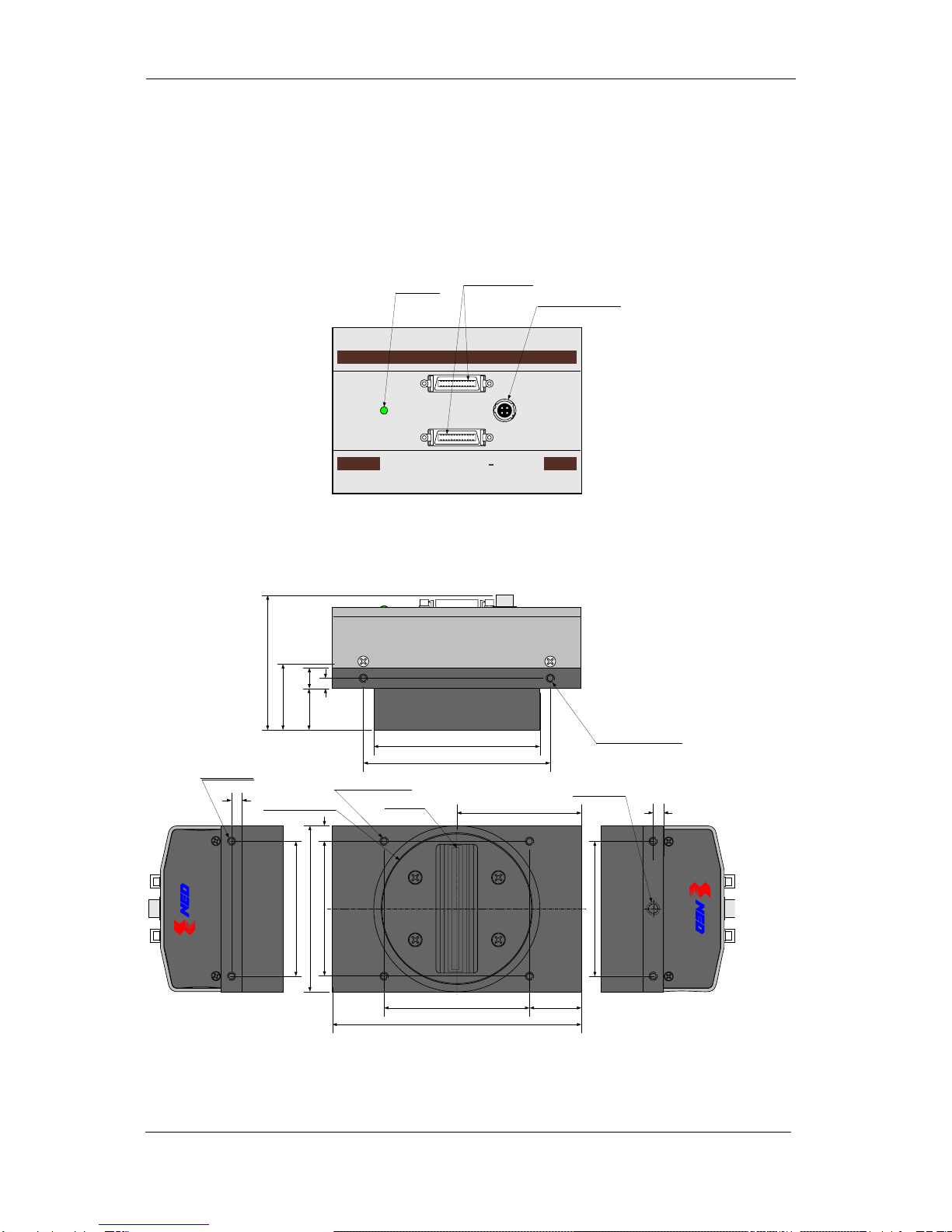
The dimensions of the camera are shown below.
M72×0.75 screw mount
NIPPON ELECTRO-SENSORY DEVICESCORP.
MADE IN JAPAN
NIPPON ELECTRO-SENSORYDEVICES CORP.
MADE IN JAPA N
DC12-15V
CL1
CL2
DIGITAL
LINESCAN
CAMERA
CLISBee
80
単位: mm
*31.8
第1ピクセル
M72 x 0.75 深さ10
(フランジバック)
10
5
(65
)
インディケータ 電源コネクタ
(HIROSE HR10A 4P)
Camera Link コネクタ
(MDR26)
65
4-M4 深さ 6 (両側面)
4-M4 深さ 8 (前面)
4-M4 深さ 6
(上面、 底面)
65
65
1/4"-20UNC
20
7.5
S
80
Ø
90
60 5
70 25
120
5
Figure 2-2-1 Dimensions of the Camera

NED
8040SAT8 UME-0005-01
14
2.3 Optical Interface
For XCM8040SAT8, M72×0.75 screw mount is available.
The amount and wavelengths of light required to capture useful images
depend on the intended use. Factors include the property, speed, the objects
spectral characteristics, exposure time, the light source characteristics, the
specifications of the acquisition system and so on.
The exposure amount (exposure time x light amount) is the most important
factor in getting desirable images. Please determine the exposure amount after
studying what is most important to your system.
Keep these guidelines in mind when setting up your light source:
LED light sources are relatively inexpensive, provide a uniform field and
longer life span compared to other light sources. However, they also
require a camera with excellent sensitivity.
Halogen light sources generally provide very little blue light but have high
infrared light (IR) proportions.
Fiber-optic light distribution systems generally transmit very little blue light
relative to IR.
Metal halide light sources are very bright but have a shorter life span
compared to other light sources.
Generally speaking, the brighter the light sources, the shorter the life span.
CMOS image sensors are sensitive to infrared (IR). We recommend using
daylight color fluorescent lamps that have low IR emissions. If you use a
halogen light source, to prevent infrared from distorting the images use an IR
cutoff filter that does not transmit wavelengths.
NED
8040SAT8 UME-0005-01
15
3 Hardware
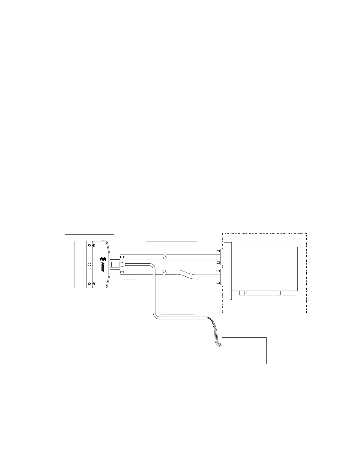
3.1 Camera Connection
Use the camera in the following way:
(1) Camera Link Full Configuration cables must be used to connect the camera
unit with the frame grabber board.
Use two cables of the same length and the same manufacturer. Use
asymmetric Camera Link Full Configuration cables and connect the camera with
the connector labeled as ”Camera side”.
(2) Connect the camera with the designated power supply.
Use the designated power cable to connect the camera with the power source
for the camera. Insert the plug end of the cable into the camera. Attach the
opposite end (loose wires) to the power unit.
Other than those above, a personal computer, a frame grabber board, a
compatible lens, a lens mount, a light source and an encoder are necessary,
depending on the situation.
Figure 3-1-1 Connections between Camera and Frame Grabber Board and Power Supply
There are two connectors available for the Camera Link Full Configuration board. Always
check the frame grabber board specifications before making connections.
PC
Camera Link
Full Configuration
Frame Grabber
Board
Line Scan Camera
(XCM8040SAT8) Camera Link Cable
(3M:14B26-SZLB-xxx-0LC)
Power Cable
Camera Power
Supply
DC +12V 15W
CL1
CL2
CL1
CL2

NED
8040SAT8 UME-0005-01
16
<Note: Regarding the choice of Camera Link cable>
Although it is not recommended to use the maximum cable length possible as
depicted in the manual, the camera will still operate fully in such cases. In the
market these days there can be found many different varieties of cables; Some for
Camera Link “Base” only, some for “Medium” etc.
We recommend that you choose the correct cable for the appropriate operational
specification of your cameras output and ensure that this cable is preferably within
but not over the maximum guaranteed length as detailed in the individual cameras
manual.
3.2 Input / Output Connectors and Indicator
The layout of input /output connecters and the LED indicator are as follows.
DC12-15V
CL1
CL2
Indicator
Power Supply Connector
(HIROSE HR10A 4P)
Camera Link
Connector (MDR26)
DIGITAL
LINESCAN
CAMERA
CLISBee S
Figure 3-2-1 Input/Output Connectors and Indicator

NED
8040SAT8 UME-0005-01
17
3.3 Connectors・Pin Assignments・Cables
This camera adopts Full Configuration of Camera Link interface standards.
Figure 3-3 shows the interface for the camera and a typical implementation for
the frame grabber interface.
Figure 3-3-1 Camera / Frame Grabber Interface
28 28
Frame Grabber BoardCamera
26-pin MDR Connector CL1
CC1(制御入力)
Cable
SerTC
SerTFG
CK60MHz
Channel Link Bus
LVAL,FVAL
DVAL,SP
PortA~C
CC2
CC3
CC4
X1±
X0±
X2±
X3±
XClk±
100Ω
100Ω
100Ω
100Ω
100Ω
100Ω
100Ω
100Ω
100Ω
100Ω
100Ω
SerTFG±
SerTC±
CC1±
CC2±
CC3±
CC4±
26-pin MDR Connector
X1±
X0±
X2±
X3±
XClk±
SerTFG±
SerTC±
CC1±
CC2±
CC3±
CC4±
LVDS_DRIVER(NS)
DS90CR285MTD
equivalent
LVDS_DRIVER/
RECEIVER(NS)
DS90LV019TM
equivalent
LVDS_RECEIVER(NS
)
DS90LV048AT
equivalent
LVDS_RECEIVER(NS)
DS90CR286MTD
recommended
LVDS_DRIVER/
RECEIVER(NS)
DS90LV019TM
recommended
LVDS_DRIVER(NS)
DS90LV047AT
recommended
28 28
26-pin MDR Connector CL2
Cable
CK60MHz
Channel Link Bus
LVAL,FVAL
DVAL,SP
PortD~F
Y1±
Y0±
Y2±
Y3±
YClk±
100Ω
100Ω
100Ω
100Ω
100Ω
100Ω
100Ω
terminated
26-pin MDR Connector
Y1±
Y0±
Y2±
Y3±
YClk±
LVDS_DRIVER(NS)
DS90CR285MTD
equivalent
LVDS_RECEIVER(NS
)
DS90CR286MTD
recommended
28
CK60MHz
Channel Link Bus
LVAL,FVAL
DVAL,SP
PortG~H
Z1±
Z0±
Z2±
Z3±
ZClk±
LVDS_DRIVER(NS)
DS90CR285MTD
equivalent
28
100Ω
100Ω
100Ω
100Ω
100Ω
Z1±
Z0±
Z2±
Z3±
ZClk±
LVDS_RECEIVER(NS
)
DS90CR286MTD
recommended
NED
8040SAT8 UME-0005-01
18
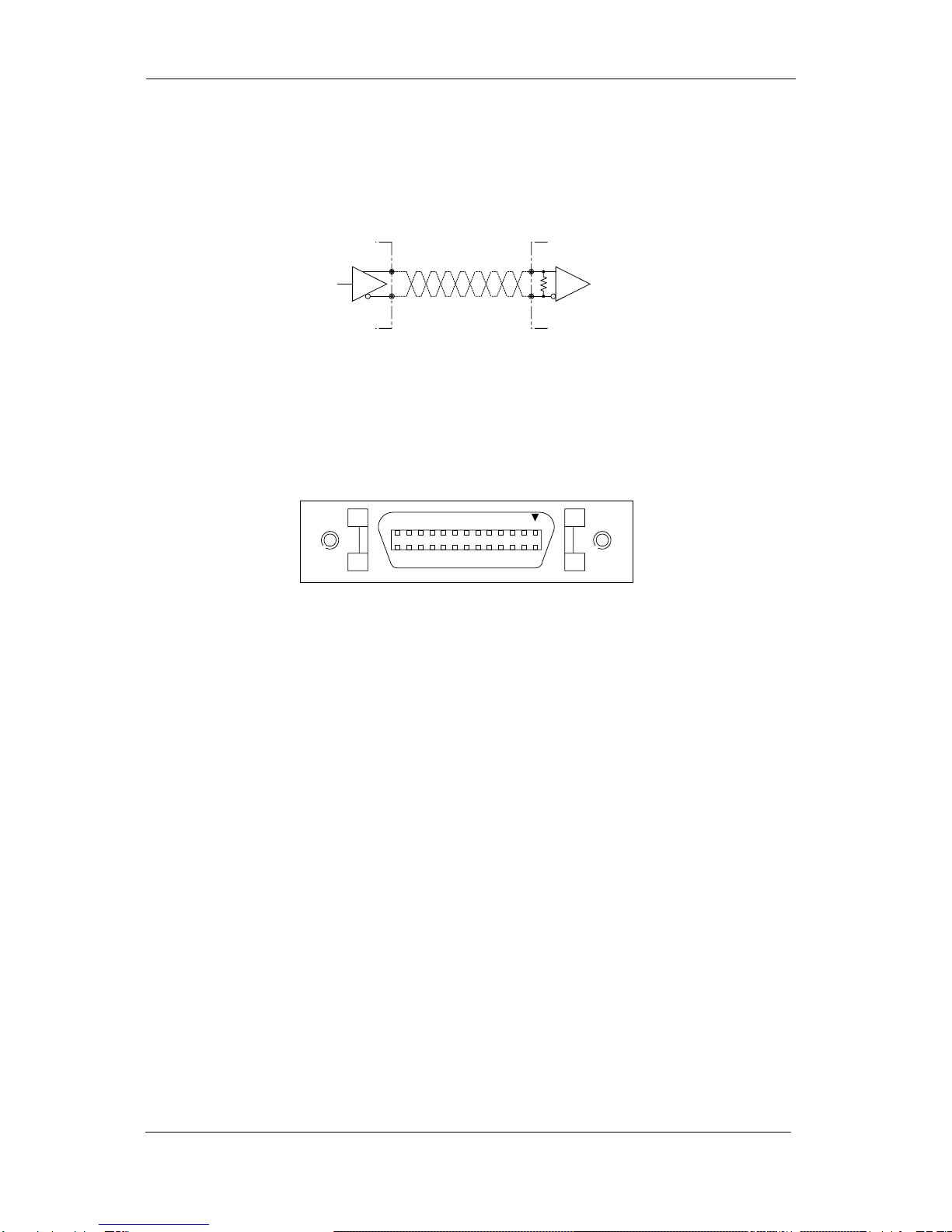
Set the LVDS, Channel Link driver side to 100 ohm termination.
Do not make the receiver side of LVDS open but set the logic to H or L, even if
not used.
Figure 3-3-2 Circuit of LVDS
The camera has 26-pin MDR connectors for control signals of Camera Link,
data signals and serial communications. The camera also has a 4-pin HIROSE
connector for power supply.
Figure 3-3-3 Camera Link Connector
Half pitch (miniature half ribbon) shape
Locking screw (UNC #4-40) type
+
-
100Ω
+
-
Driver Receiver
H or L
1
14
2
15
3
16
11
24
12
25
13
26

NED
8040SAT8 UME-0005-01
19
Table 3-3-1 Camera Link Connector (26-pin MDR Connector) pin assignments
CL1(Base Configuration) CL2(Full Configuration)
No NAME No NAME I/O
1 Inner Shield 14 Inner Shield
2 X0- 15 X0+ Out
3 X1- 16 X1+ Out
4 X2- 17 X2+ Out
5 Xclk- 18 Xclk+ Out
6 X3- 19 X3+ Out
7 SerTC+ 20 SerTC- In
8 SerTFG- 21 SerTFG+ Out
9 CC1- 22 CC1+ In
10 CC2+ 23 CC2- In
11 CC3- 24 CC3+ In
12 CC4+ 25 CC4- In
13 Inner Shield 26 Inner Shield
Explanation of Signals
Inner Shield : Shield cable (GND)
X0+,X0-…X3+,X3- : Data output (Channel Link)
Xclk+,Xclk- : Clock output for above data output synchronization (Channel
Link)
Y0+,Y0-…Y3+,Y3- : Data output (Channel Link)
Yclk+,Yclk- : Clock output for above data output synchronization (Channel
Link)
Z0+,Z0-…Z3+,Z3- : Data output (Channel Link)
Zclk+,Zclk- : Clock output for above data output synchronization (Channel
Link)
SerTC+, SerTC- : Serial data input (LVDS)
SerTFG+, SerTFG- : Serial data output (LVDS)
CC1+,CC1- : External synchronous signal input (LVDS)
CC2+,CC2- : Not in use (LVDS)
CC3+,CC3- : Not in use (LVDS)
CC4+,CC4- : Not in use (LVDS)
Camera Link compatible cable
3M: 14B26 – SZLB – xxx - 0LC by or equivalent
No NAME No NAME I/O
1 Inner Shield 14 Inner Shield
2 Y0- 15 Y0+ Out
3 Y1- 16 Y1+ Out
4 Y2- 17 Y2+ Out
5 Yclk- 18 Yclk+ Out
6 Y3- 19 Y3+ Out
7100Ωterminated 20 100Ωterminated
8 Z0- 21 Z0+ Out
9 Z1- 22 Z1+ Out
10 Z2- 23 Z2+ Out
11 Zclk- 24 Zclk+ Out
12 Z3- 25 Z3+ Out
13 Inner Shield 26 Inner Shield

NED
8040SAT8 UME-0005-01
20
To avoid uncoupling of the cable connectors during power on, make sure to
clamp them with the locking screws.
Do not unplug the cables while power is being supplied to the camera.
The pin assignment of the power supply connector is shown below.
Figure 3-3-4 Power Supply Connector (HIROSE : HR10A - 7P- 4S)
Round shape push-pull lock type
Table 3-3-2 Pin Assignment of Power Supply Connector
No NAME Color of Cable
1 12 -15V White
2 12 -15V Red
3 GND Green
4 GND Black
3.4 Power Supply
The camera requires a single power supply (DC+12 to +15V).
When selecting a power source, choose one with the capacity to allow
for in-rush current. (15W or more recommended)
Insert the cable plug securely until it locks into position. This is to prevent the
connector from coming loose during power transmission.
Acceptable Cable (Acceptable plug):DGPS -10 (HIROSE : HR10A -7P - 4S)
Power supply voltage: DC+12 -15V (+/-5%)
Consumption Current (rated): DC+12V : 500mA
LED lamp illuminates when +12V to +15V power is being supplied to the
camera.
If the lamp fails to illuminate even after power is switched on, turn OFF power
immediately. Inspect wiring. Check the voltage and capacity of the supplied
power source.
1
2
4
3
Table of contents
Other NED Security Camera manuals


