COMPRO IP55 User manual

Network Camera
IP55
IP60
IP70
Model No.
V2-110328

Copyright
© 2011 Compro Technology, Inc. All rights reserved.
Trademark
Compro Technology is the registered trademarks of Compro Technology Inc.
Seedonk and Seedonk Messenger are registered trademarks of Seedonk Inc. All other company and
product names mentioned in this document are registered trademarks of the respective companies.
Restriction
No part of this document may be copied or reproduced in any form or by any means without the prior
written consent of Compro Technology, Inc.
Disclaimer
Compro Technology makes no warranties with respect to this documentation and disclaims any implied
warranties of merchantability, quality, or fitness for any particular purpose. The information in this
document is subject to change without notice. COMPRO reserves the right to make revisions to this
publication without obligation to notify any person or entity of any such changes.
Revision History
2011/03/28 Revised Recording Setup section
2011/01/19 Original version
Compro Technology Inc.
www.comprosecurity.com
Tel. +886 2 2918 0169, Fax +886 2 2915 2389
3F, No.12, Alley 6, Lane 45, Pao Shin Road,
Hsintien District, New Taipei City 231, Taiwan

Contents
Compro IP55/60/70 Network Camera
Contents
Chapter 1: Important Notices . . . . . . . . . . . . . . . . . . . . . . . . . . . . . . . . . . . . . . . . . . . . . . . . . . . . . .1-1
Regulatory Notice . . . . . . . . . . . . . . . . . . . . . . . . . . . . . . . . . . . . . . . . . . . . . . . . . . . . . . . . . . 1-1
Operation Safety . . . . . . . . . . . . . . . . . . . . . . . . . . . . . . . . . . . . . . . . . . . . . . . . . . . . . . . . . . . 1-1
About this Manual . . . . . . . . . . . . . . . . . . . . . . . . . . . . . . . . . . . . . . . . . . . . . . . . . . . . . . . . . . 1-2
Conventions in this Manual . . . . . . . . . . . . . . . . . . . . . . . . . . . . . . . . . . . . . . . . . . . . . . . . . . . . 1-2
Chapter 2: Product Overview. . . . . . . . . . . . . . . . . . . . . . . . . . . . . . . . . . . . . . . . . . . . . . . . . . . . . . . 2-1
Package Contents . . . . . . . . . . . . . . . . . . . . . . . . . . . . . . . . . . . . . . . . . . . . . . . . . . . . . . . . . . 2-1
Features . . . . . . . . . . . . . . . . . . . . . . . . . . . . . . . . . . . . . . . . . . . . . . . . . . . . . . . . . . . . . . . .2-2
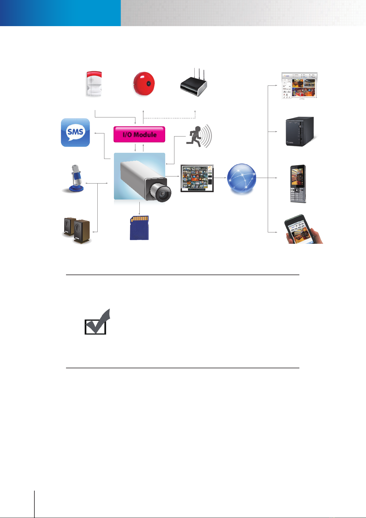
Application Diagram . . . . . . . . . . . . . . . . . . . . . . . . . . . . . . . . . . . . . . . . . . . . . . . . . . . . . . . .2-4
Camera Layout . . . . . . . . . . . . . . . . . . . . . . . . . . . . . . . . . . . . . . . . . . . . . . . . . . . . . . . . . . . . 2-5
LED Status Indicator . . . . . . . . . . . . . . . . . . . . . . . . . . . . . . . . . . . . . . . . . . . . . . . . . . . . . . . . . 2-7
Digital I/O Connector Block . . . . . . . . . . . . . . . . . . . . . . . . . . . . . . . . . . . . . . . . . . . . . . . . . . . . 2-8
Chapter 3: Installation . . . . . . . . . . . . . . . . . . . . . . . . . . . . . . . . . . . . . . . . . . . . . . . . . . . . . . . . . . . 3-1
Connecting the Cables . . . . . . . . . . . . . . . . . . . . . . . . . . . . . . . . . . . . . . . . . . . . . . . . . . . . . . . 3-1
Wireless Connection. . . . . . . . . . . . . . . . . . . . . . . . . . . . . . . . . . . . . . . . . . . . . . . . . . . . . . . . . 3-2
Disassembling and Assembling the Camera Stand . . . . . . . . . . . . . . . . . . . . . . . . . . . . . . . . . . . . .3-3
Mounting the Camera . . . . . . . . . . . . . . . . . . . . . . . . . . . . . . . . . . . . . . . . . . . . . . . . . . . . . . .3-4
Dismounting the Camera . . . . . . . . . . . . . . . . . . . . . . . . . . . . . . . . . . . . . . . . . . . . . . . . . . . . .3-5
Installing Camera Software . . . . . . . . . . . . . . . . . . . . . . . . . . . . . . . . . . . . . . . . . . . . . . . . . . . .3-6
Chapter 4: Accessing Camera . . . . . . . . . . . . . . . . . . . . . . . . . . . . . . . . . . . . . . . . . . . . . . . . . . . . . .4-1
Viewing Streamed Video . . . . . . . . . . . . . . . . . . . . . . . . . . . . . . . . . . . . . . . . . . . . . . . . . . . . . . 4-1
Accessing via PC Web Browser . . . . . . . . . . . . . . . . . . . . . . . . . . . . . . . . . . . . . . . . . . . . . . . . . .4-2
Accessing via iPhone/Smartphone . . . . . . . . . . . . . . . . . . . . . . . . . . . . . . . . . . . . . . . . . . . . . . .4-5
Accessing via 3GPP Mobile Phone . . . . . . . . . . . . . . . . . . . . . . . . . . . . . . . . . . . . . . . . . . . . . . . . 4-6
Accessing via Seedonk IM Client . . . . . . . . . . . . . . . . . . . . . . . . . . . . . . . . . . . . . . . . . . . . . . . . . 4-7
Chapter 5: Live View . . . . . . . . . . . . . . . . . . . . . . . . . . . . . . . . . . . . . . . . . . . . . . . . . . . . . . . . . . . .5-1
Page Layout . . . . . . . . . . . . . . . . . . . . . . . . . . . . . . . . . . . . . . . . . . . . . . . . . . . . . . . . . . . . . . 5-1
Icons on Live View Page . . . . . . . . . . . . . . . . . . . . . . . . . . . . . . . . . . . . . . . . . . . . . . . . . . . . . .5-2
Top Panel . . . . . . . . . . . . . . . . . . . . . . . . . . . . . . . . . . . . . . . . . . . . . . . . . . . . . . . . . . . . .5-2
Left Panel . . . . . . . . . . . . . . . . . . . . . . . . . . . . . . . . . . . . . . . . . . . . . . . . . . . . . . . . . . . . .5-2
Others . . . . . . . . . . . . . . . . . . . . . . . . . . . . . . . . . . . . . . . . . . . . . . . . . . . . . . . . . . . . . . .5-2
Enable Digital Zoom. . . . . . . . . . . . . . . . . . . . . . . . . . . . . . . . . . . . . . . . . . . . . . . . . . . . . . . . . 5-3
Voice Communication . . . . . . . . . . . . . . . . . . . . . . . . . . . . . . . . . . . . . . . . . . . . . . . . . . . . . . .5-4
Chapter 6: Conguration . . . . . . . . . . . . . . . . . . . . . . . . . . . . . . . . . . . . . . . . . . . . . . . . . . . . . . . . . 6-1
Main Setup Page . . . . . . . . . . . . . . . . . . . . . . . . . . . . . . . . . . . . . . . . . . . . . . . . . . . . . . . . . . . 6-1
Video Settings . . . . . . . . . . . . . . . . . . . . . . . . . . . . . . . . . . . . . . . . . . . . . . . . . . . . . . . . . . . .6-2
Video Mode . . . . . . . . . . . . . . . . . . . . . . . . . . . . . . . . . . . . . . . . . . . . . . . . . . . . . . . . . . . . 6-2
Stream Setting . . . . . . . . . . . . . . . . . . . . . . . . . . . . . . . . . . . . . . . . . . . . . . . . . . . . . . . . . . 6-2
Active Bandwidth Management . . . . . . . . . . . . . . . . . . . . . . . . . . . . . . . . . . . . . . . . . . . . . . . 6-2
Video Preference . . . . . . . . . . . . . . . . . . . . . . . . . . . . . . . . . . . . . . . . . . . . . . . . . . . . . . . . . 6-3
Camera Settings . . . . . . . . . . . . . . . . . . . . . . . . . . . . . . . . . . . . . . . . . . . . . . . . . . . . . . . . . . .6-3
Video Properties . . . . . . . . . . . . . . . . . . . . . . . . . . . . . . . . . . . . . . . . . . . . . . . . . . . . . . . . . 6-3
White Balance . . . . . . . . . . . . . . . . . . . . . . . . . . . . . . . . . . . . . . . . . . . . . . . . . . . . . . . . . .6-3
Backlight Compensation. . . . . . . . . . . . . . . . . . . . . . . . . . . . . . . . . . . . . . . . . . . . . . . . . . . .6-4
Flickerless . . . . . . . . . . . . . . . . . . . . . . . . . . . . . . . . . . . . . . . . . . . . . . . . . . . . . . . . . . . . . 6-4
Exposure Control. . . . . . . . . . . . . . . . . . . . . . . . . . . . . . . . . . . . . . . . . . . . . . . . . . . . . . . . . 6-4
Low Light Behavior . . . . . . . . . . . . . . . . . . . . . . . . . . . . . . . . . . . . . . . . . . . . . . . . . . . . . . .6-4
LED Indicator . . . . . . . . . . . . . . . . . . . . . . . . . . . . . . . . . . . . . . . . . . . . . . . . . . . . . . . . . . . 6-4
IR Light Control (IP70 only) . . . . . . . . . . . . . . . . . . . . . . . . . . . . . . . . . . . . . . . . . . . . . . . . . .6-5
Embed Text and Image . . . . . . . . . . . . . . . . . . . . . . . . . . . . . . . . . . . . . . . . . . . . . . . . . . . . . 6-5
Flip Mode . . . . . . . . . . . . . . . . . . . . . . . . . . . . . . . . . . . . . . . . . . . . . . . . . . . . . . . . . . . . .6-5
Audio Settings . . . . . . . . . . . . . . . . . . . . . . . . . . . . . . . . . . . . . . . . . . . . . . . . . . . . . . . . . . . .6-6

Contents
Compro IP55/60/70 Network Camera
User Settings . . . . . . . . . . . . . . . . . . . . . . . . . . . . . . . . . . . . . . . . . . . . . . . . . . . . . . . . . . . . .6-6
Network Settings. . . . . . . . . . . . . . . . . . . . . . . . . . . . . . . . . . . . . . . . . . . . . . . . . . . . . . . . . . . 6-7
Ethernet . . . . . . . . . . . . . . . . . . . . . . . . . . . . . . . . . . . . . . . . . . . . . . . . . . . . . . . . . . . . . . 6-7
Wireless . . . . . . . . . . . . . . . . . . . . . . . . . . . . . . . . . . . . . . . . . . . . . . . . . . . . . . . . . . . . . .6-7
Network Diagnostic . . . . . . . . . . . . . . . . . . . . . . . . . . . . . . . . . . . . . . . . . . . . . . . . . . . . . . . 6-8
Network Bandwidth. . . . . . . . . . . . . . . . . . . . . . . . . . . . . . . . . . . . . . . . . . . . . . . . . . . . . . . 6-8
Advanced . . . . . . . . . . . . . . . . . . . . . . . . . . . . . . . . . . . . . . . . . . . . . . . . . . . . . . . . . . . . .6-8
DDNS . . . . . . . . . . . . . . . . . . . . . . . . . . . . . . . . . . . . . . . . . . . . . . . . . . . . . . . . . . . . . . . . 6-9
UPnP . . . . . . . . . . . . . . . . . . . . . . . . . . . . . . . . . . . . . . . . . . . . . . . . . . . . . . . . . . . . . . . .6-9
RTP . . . . . . . . . . . . . . . . . . . . . . . . . . . . . . . . . . . . . . . . . . . . . . . . . . . . . . . . . . . . . . . . .6-9
Event Setup . . . . . . . . . . . . . . . . . . . . . . . . . . . . . . . . . . . . . . . . . . . . . . . . . . . . . . . . . . . . . 6-10
Event Server Setup . . . . . . . . . . . . . . . . . . . . . . . . . . . . . . . . . . . . . . . . . . . . . . . . . . . . . .6-10
Trigger Setup . . . . . . . . . . . . . . . . . . . . . . . . . . . . . . . . . . . . . . . . . . . . . . . . . . . . . . . . . . 6-11
Motion Detection Setup . . . . . . . . . . . . . . . . . . . . . . . . . . . . . . . . . . . . . . . . . . . . . . . . . . . 6-12
I/O Status . . . . . . . . . . . . . . . . . . . . . . . . . . . . . . . . . . . . . . . . . . . . . . . . . . . . . . . . . . . .6-12
Audio Detection . . . . . . . . . . . . . . . . . . . . . . . . . . . . . . . . . . . . . . . . . . . . . . . . . . . . . . . . 6-12
Recording Setup . . . . . . . . . . . . . . . . . . . . . . . . . . . . . . . . . . . . . . . . . . . . . . . . . . . . . . . . . . 6-13
Recording History . . . . . . . . . . . . . . . . . . . . . . . . . . . . . . . . . . . . . . . . . . . . . . . . . . . . . . . . . 6-14
Date Setup. . . . . . . . . . . . . . . . . . . . . . . . . . . . . . . . . . . . . . . . . . . . . . . . . . . . . . . . . . . . . . 6-14
Multi-Camera . . . . . . . . . . . . . . . . . . . . . . . . . . . . . . . . . . . . . . . . . . . . . . . . . . . . . . . . . . . . 6-14
Chapter 7: Event Viewer . . . . . . . . . . . . . . . . . . . . . . . . . . . . . . . . . . . . . . . . . . . . . . . . . . . . . . . . . . 7-1
Chapter 8: Maintenance . . . . . . . . . . . . . . . . . . . . . . . . . . . . . . . . . . . . . . . . . . . . . . . . . . . . . . . . . . 8-1
Information . . . . . . . . . . . . . . . . . . . . . . . . . . . . . . . . . . . . . . . . . . . . . . . . . . . . . . . . . . . . . . 8-1
Log . . . . . . . . . . . . . . . . . . . . . . . . . . . . . . . . . . . . . . . . . . . . . . . . . . . . . . . . . . . . . . . . . . .8-1
Maintenance . . . . . . . . . . . . . . . . . . . . . . . . . . . . . . . . . . . . . . . . . . . . . . . . . . . . . . . . . . . . . 8-1
Prole Management . . . . . . . . . . . . . . . . . . . . . . . . . . . . . . . . . . . . . . . . . . . . . . . . . . . . . .8-2
Reset All Settings to Default. . . . . . . . . . . . . . . . . . . . . . . . . . . . . . . . . . . . . . . . . . . . . . . . . . 8-2
Firmware Update . . . . . . . . . . . . . . . . . . . . . . . . . . . . . . . . . . . . . . . . . . . . . . . . . . . . . . . .8-2
Chapter 9: Troubleshooting. . . . . . . . . . . . . . . . . . . . . . . . . . . . . . . . . . . . . . . . . . . . . . . . . . . . . . . . 9-1
Reconguring Your Device. . . . . . . . . . . . . . . . . . . . . . . . . . . . . . . . . . . . . . . . . . . . . . . . . . . . . 9-1
Cabling Check. . . . . . . . . . . . . . . . . . . . . . . . . . . . . . . . . . . . . . . . . . . . . . . . . . . . . . . . . . . . . 9-1
Reset to the Factory Default Settings . . . . . . . . . . . . . . . . . . . . . . . . . . . . . . . . . . . . . . . . . . . . . . 9-2
Trouble with the ActiveX Client . . . . . . . . . . . . . . . . . . . . . . . . . . . . . . . . . . . . . . . . . . . . . . . . .9-3
No user interface in the browser: . . . . . . . . . . . . . . . . . . . . . . . . . . . . . . . . . . . . . . . . . . . . . .9-3
Trouble with Remote Viewing on Browser . . . . . . . . . . . . . . . . . . . . . . . . . . . . . . . . . . . . . . . . . . . 9-5
DDNS Conguration. . . . . . . . . . . . . . . . . . . . . . . . . . . . . . . . . . . . . . . . . . . . . . . . . . . . . . . . . 9-7
Symptoms, Causes and Solutions . . . . . . . . . . . . . . . . . . . . . . . . . . . . . . . . . . . . . . . . . . . . . . . .9-8
Contacting Compro Technical Support . . . . . . . . . . . . . . . . . . . . . . . . . . . . . . . . . . . . . . . . . . . . 9-12
Chapter 10: Technical Specications . . . . . . . . . . . . . . . . . . . . . . . . . . . . . . . . . . . . . . . . . . . . . . . . . 10-1
Chapter 11: Appendix . . . . . . . . . . . . . . . . . . . . . . . . . . . . . . . . . . . . . . . . . . . . . . . . . . . . . . . . . . 11-1
IP55 Available Video Modes . . . . . . . . . . . . . . . . . . . . . . . . . . . . . . . . . . . . . . . . . . . . . . . . . . . 11-1
IP60 Available Video Modes . . . . . . . . . . . . . . . . . . . . . . . . . . . . . . . . . . . . . . . . . . . . . . . . . . . 11-2
IP70 Available Video Modes . . . . . . . . . . . . . . . . . . . . . . . . . . . . . . . . . . . . . . . . . . . . . . . . . . . 11-3
List of Compatible DVR / NVR / NAS . . . . . . . . . . . . . . . . . . . . . . . . . . . . . . . . . . . . . . . . . . . . . . 11-3
List of Figures and Tables. . . . . . . . . . . . . . . . . . . . . . . . . . . . . . . . . . . . . . . . . . . . . . . . . . . . . 11-4

1-1
Chapter 1: Important Notices
Regulatory Notice
This device complies with Part 15 of the FCC Rules. Operation is subject to the following two conditions: (1)
This device may not cause harmful interference, and (2) This device must accept any interference received,
including interference that may cause undesired operation.
FCC Interference Statement
This equipment has been tested and found to comply with the limits for a Class B digital device, pursuant
to Part 15 of the FCC Rules. These limits are designed to provide reasonable protection against harmful
interference in a residential installation.
This equipment generates, uses and can radiate radio frequency energy and, if not installed and used in
accordance with the instructions, may cause harmful interference to radio communications. However, there is
no guarantee that interference will not occur in a particular installation. If this equipment does cause harmful
interference to radio or television reception, which can be determined by turning the equipment o and on,
the user is encouraged to try to correct the interference by one of the following measures:
• Reorientorrelocatethereceivingantenna.
• Increasetheseparationbetweentheequipmentandreceiver.
• Connecttheequipmentintoanoutletonacircuitdierentfromthattowhichthereceiverisconnected.
• Consultthedealeroranexperiencedradio/TVtechnicianforhelp.
To assure continued compliance, any changes or modifications not expressly approved by the party
responsible for compliance could void the user's authority to operate this equipment.
Operation Safety
Before starting using the camera, please read and follow the steps below to protect your IP camera.
• PleaseplacetheIPcameraonalevelsurfaceandoutofdirectsunshine.
• PleasekeeptheIPcameraindoorsandawayfromwater,dust,humidityormagneticproducts.
• PleasedonotdroptheIPCamerabodytotheoor;itmaycausethedamagetomainparts.
• Pleasedonotdisassembleorremodeltheproduct;itmaycausedamageorre.
• Donotshake,moveordisturbtheIPcamerawhenitisinoperation,assuchactionsmayresultinthe
malfunction of the device.
• PowerotheIPCameraassoonasitisfoundsmokingorsmeltunusual.
• PleasedonotplacetheIPCameraaroundtheheatsources,suchastelevisionormicrowaveoven.
Regulatory Notice & Operation Safety

1-2
Compro IP55 / 60 / 70 Network Camera
About this Manual
This manual is only intended for the users of Compro IP55, IP60, and IP70 network camera, and is applicable
for rmware release 2.0. The camera appears on the cover of this manual is a IP60 which diers with IP55 and
IP70 in appearance.
Conventions in this Manual
While you are using this manual, pay attention to some symbols and notations that are used to draw
attention to special situations such as:
Caution!
Information provided here is critical to prevent damage to the product
or injury to the user.
!
Important:
Here it provides instructions that a user must follow in order to complete
a task.
Note:
Additional information or tips to help the user operate the product.
About this Manual & Conventions in this Manual

2-1
Chapter 2: Product Overview
Package Contents
Please check the package contents on your hand. If anything is missing, please don’t hesitate to contact your
local distributor.
Figure 2-1. Parts list
Network Camera
RJ-45 LAN Cable
Power Adaptor
Quick Start Guide
Installation CD
Mounting Screw x 3 /Screw Mount x 3
Package Contents

2-2
Compro IP55 / 60 / 70 Network Camera
Features
The camera is an easy-to-install product for the indoor xed camera solution. Its support of the H.264/MPEG-
4/MJPEG video compression format helps achieve superior performance and high video quality in small
recording le size, which means a much lower cost for data storage. Utilizing smart motion detection and
built-in 2-way audio for fast and easy communications, The camera ensures instant responses when security
is compromised. The camera also comes with a built-in microSD slot for local image storage.
IP55 Full Feature List
• 1/4”CMOSMegapixelsensor
• Supportsreal-timeMPEG-4andMJPEGcompression(DualCodec)
• Supportsdualstreamssimultaneously
• Support10xdigitalzoom
• Videoresolutionisupto1280x1024pixels
• Imageframerateisupto30framesunder640x480or15framesunder1280x1024
• Smartmotiondetection
• Two-wayaudiowithbuilt-inMICandspeaker
• SupportUPnP(universalplugandplay)
• Support10/100802.3/Ethernet
• 802.11b/g/nWLANonapplicablemodel(Optionalwirelessadaptor)
• DigitalI/OforExternalSensorandAlarm(2In/1Out)
• Supportslocalstorage(microSD/SDHC),Snapshot
• EasytoInstallwithIPcameraWizard
• RemoteMonitoringon3GPPmobilephonesorphoneswithwebbrowser(e.g.iPhone/BlackBerry)
• Bundledpowerful32-channelIPvideomanagementsoftware---ComproView
IP60 Full Feature List
• 1/3"CMOSMegapixelsensor
• Supportsreal-timeH.264,MPEG-4andMJPEGcompression(TripleCodec)
• Supportsdualstreamssimultaneously
• Support10xdigitalzoom
• Videoresolutionupto1280x1024pixels
• Imageframerateupto30framesat640x480or15framesat1280x1024
• Smartmotiondetection
• Two-wayaudiowithbuilt-inMICandspeaker
• SupportsUPnP(universalplugandplay)
• Supports10/100802.3/Ethernet
• 802.11b/g/nWLANonapplicablemodel(optionalwirelessadaptor)
Features

2-3
Chapter 2: Product Overview
• DigitalI/OforExternalSensorandAlarm(2In/1Out)
• Supportslocalstorage(microSD),Snapshot
• EasytoInstallwithIPcameraWizard
• RemoteMonitoringon3GPPmobilephonesorphoneswithwebbrowser(e.g.iPhone/BlackBerry)
• Bundledpowerful32-channelIPvideomanagementsoftware---ComproView
IP70 Full Feature List
• 1/3”CMOSMegapixelsensor
• DayandnightfunctionalitywithmechanicalIRcutlterswitching
• Built-inIRlampwithlightsensor
• Supportsreal-timeH.264,MPEG-4andMJPEGcompression(TripleCodec)
• Supportsdualstreamssimultaneously
• Support10xdigitalzoom
• Videoresolutionisupto1280x1024pixels
• Imageframerateisupto30framesunder640x480or15framesunder1280x1024
• Smartmotiondetection
• Two-wayaudiowithbuilt-inMICandspeaker
• SupportsUPnP(universalplugandplay)
• Supports10/100802.3/Ethernet
• 802.11b/g/nWLANonapplicablemodel(Optionalwirelessadaptor)
• DigitalI/OforExternalSensorandAlarm(2In/1Out)
• Supportslocalstorage(microSD),Snapshot
• EasytoInstallwithIPcameraWizard
• RemoteMonitoringon3GPPmobilephonesorphoneswithwebbrowser(e.g.iPhone/BlackBerry)
• Bundledpowerful32-channelIPvideomanagementsoftware---ComproView
Features

2-4
Compro IP55 / 60 / 70 Network Camera
Application Diagram
I/O Module
I/O Input
Sensor
I/O Output
Alarm
Wireless
Module
Video
Analytics
32-CH ComproView
iPhone
16-CH WebVUer
NAS / NVR
3GPP
microSD/SDHC
Local Storage
Audio Input
Audio Output
Internet
Figure 2-2. Application diagram
Important:
Begining from firmware version 2.0, 3rd-party NAS / NVR support
on this Compro IP camera is currently limited to the usage of RTSP
(Real Time Streaming Protocol) protocol. Support for other protocols,
namely samba-based CIFS and NFS, is only available in older
firmware. In particular, only certain NAS / NVR products from select
manufacturers are supported by this camera. For the list of compatible
NASproducts,pleaserefertothe"List of Compatible DVR /NVR / NAS"
section in the appendix. Compro does not guarantee other DVR/
NVR / NAS products not on the list will work properly with this Compro
IP camera.
Application Diagram

2-5
Chapter 2: Product Overview
Camera Layout
For the IP55 and IP60 camera.
Figure 2-3. Front and rear view of IP55/IP60
Lens.
Microphone
Speaker
LED status indicator
Wireless adaptor connector (USB type)
Audio Output
Reset Button
microSD card slot (on the side)
Microphone Input
Power connector
Ethernet Port
I/O port (2 in / 1 out)
Camera Layout

2-6
Compro IP55 / 60 / 70 Network Camera
For the IP70 camera.
6 12 13 14
10
5114
21 3 7 98
Figure 2-4. Front and rear view of IP70
Light sensor.
Lens
IR Lamp x 6 (inside)
Microphone
Speaker
LED status indicator
USB Wireless adaptor connector
Audio Output
Reset Button
microSD card slot (on the side)
Microphone Input
Power connector
Microphone Input
Power connector
Camera Layout

2-7
Chapter 2: Product Overview
LED Status Indicator
When you power on the camera, it will start booting procedure. There are one blue LED and one red LED
inside the camera case. Depending on the booting status, the LED indicator will be lit in the followings way:
1. About 25 seconds after powering on the IP camera, both the blue LED and red LED indicator will
become lit (appears purple).
2. About 35 seconds after powering on the IP camera, the red LED will be turned o.
3. Cameratryingtoconnecttonetwork:bothblue&redLEDashingatanintervalof0.5second.
4. Camera established connection: blue LED constantly on (Red LED o)
5. Camerafailedtoconnect:ashingredLED.(BlueLEDo )
Red LED Blue LED Indication
On On System booting up
O On Successfully established network connection
On O Performing hardware test
O O Powered o
Blinking (every 0.5 sec.) O Failed to connect to network / failed to
establish a WPS connection
O Blinking (every 0.5 sec.) Attempting to establish a WPS connection
O Blinking (every 0.2 sec.
in a 3-second period) Successfully established a WPS connection
Blinking (every 0.5 sec.) Blinking Attempting to establish network connection
Table 2-1. LED status
Figure 2-5. Normal connection
LED Status Indicator

2-8
Compro IP55 / 60 / 70 Network Camera
Digital I/O Connector Block
The I/O connector on the back of the camera provides a central interface between your home security system
and various output devices.
The two digital inputs are normally used with security sensors, e.g. passive infrared sensors (PIR), smoke
detectors, door/window sensors, etc. They work by detecting a change in the state of open and closed circuit.
You can check the status of the circuit in [Setup] > [Event Setup] > [I/O Status].
The output port is normally used to trigger external audio or visual indicators, e.g. sirens or strobe lights, etc.
Pin Name Specications Note
1 – 4 Digital Input Ports 1 & 2 Max 5VDC, 60mA Floating, TTL
5 - 7 Digital Output Port Max 24V DC, 1A or
Max 125V AC, 1A
You can only use either
the Normally Open (NO) or
Normally Closed (NC) at any
given time.
Table 2-2. Buttons in recording history
Figure 2-6. Front and rear view
Note:
The above output scenario is where the siren will only sound when the input has
been triggered. Should you wish to use the opposite way in which the output device
keeps staying on until the input has been triggered, please use NC.
IP55/60/70 IP55/60/70
Digital I/O Connector Block

3-1
Chapter 3: Installtion
Chapter 3: Installation
Connecting the Cables
The picture below shows the basic connection of your IP camera.
Figure 3-1. Connection of cables
LAN cable from PC to hub/router: If your LAN cable from PC has been connected to the Cable/ADSL
modem, please re-connect it to the Ethernet port of your hub/router.
Ethernet port on camera: Use the bundled RJ-45 LAN cable to connect the Ethernet port of the IP
camera to the Ethernet port of your hub/router.
Wireless adaptor (Optional accessory): If you have purchased the Compro USB wireless adaptor for
wireless connection, please plug it into the USB port of IP camera for wireless reception.
Power: Attach the power adaptor to the camera’s power connector and connect the power plug to a
power outlet.
Caution!
• ThewirelessconnectionportonlysupportstheComprowirelessadaptors
;pleasedonotuseotherUSBadaptorsonComproIPcamera.Shouldyou
remove the wireless adaptor during camera operation, you need to power
o the camera rst before re-plugging it.
• Whenyouunplugthepowerplugfromthewalloutletwhilethecamerais
still in operation, wait for 4 seconds before plugging the power plug back
in the wall outlet. And avoid too frequent plugging and unplugging of
power cable.
• Ifthepowercableandthenetworkcableconnectedtothecameraarenot
securely fastened, it could lead to unstable connection.
Connecting the Cables

3-2
Compro IP55 / 60 / 70 Network Camera
Wireless Connection
With the Compro wireless adaptor installed, you can also opt for using the wireless connection. Please keep in
mind that you can only have one active connection at a given time, either through LAN or wireless network.
If you connect the IP camera to the Intranet, then the same group of users can share the access of IP
camera. Please also ensure that the wireless adaptor has been securely installed, or it could lead to unstable
connection.
If the wireless connection drops randomly or plainly seems slow, try bringing your IP camera in closer
proximity to the wireless AP/router and then see if the situation improves.
!
Important:
• Havingmorewallsandceilingsbetweenthewirelesslyconnected
Compro camera and your wireless AP/router will negatively aect your
wireless connection speed. Generally, the number of walls and ceilings
shall be kept in minimum.
• Materialsandobjectslikesolidmetal,aluminum,steel,water,brick,
and concrete will weaken the strength of the wireless signal. Allow
the wireless signal from your wirelessly connected camera and your
wireless AP/router to pass through open doorways when positioning
them.
• Theoperationofthewirelessnetworkmaybeinterferedshouldthere
be other 2.4 GHz devices working in the vicinity, e.g. microwave oven,
digital cordless camera, etc. You may experience slow frame rate or
dropsofconnection;insuchsituation,wesuggestyoutrymovingthe
IP camera away from the area or turning o other appliances.
• Sincewirelesscamerascancauseinterferencesontransmission,you
may encounter erratic behavior when there are more than 10 cameras
operating in close proximity.
• Thedefaultwirelessconnectionmethoduses802.11nstandardand
you should experience a stable connection on your camera within 20
meters of the access point. .
Wireless Connection

3-3
Chapter 3: Installtion
Disassembling and Assembling the Camera Stand
The camera is already installed on the camera stand when delivered from Compro. If you need to disassemble
and assemble the stand, please refer to the pictures below.
Disassembly
Pleaseuseaatbladescrewdrivertodisassemble.
Figure 3-2. Disassembly of camera stand
Assembly
Figure 3-3. Assembly of camera stand
Disassembling and Assembling the Camera Stand

3-4
Compro IP55 / 60 / 70 Network Camera
Mounting the Camera
If you want to mount the camera on the wall or ceiling, please use the screws to fix the bracket to a flat
surface. After the bracket is fixed to a flat surface, please try to adjust the camera to the desired viewing
angle. Follow the steps below to mount the camera.
Step 1: Detach the metal mounting plate from the base of mounting bracket by inserting a flat blade
screwdriver into the rectangular hole seen on the wide end of the bracket base and then pressing the
screwdriver downward.
Figure 3-4. Detaching mounting plate
Step 2: Place the side of the mounting plate that has protruding screw holes against the mounting surface.
Screw the mounting plate into the mounting holes on the mounting surface. And secure the bracket
to the mounting plate by clicking the plate into its position, as shown in the point 1 and 2 of the
gure below.
OK
2
1
Figure 3-5. Mounting the camera
Caution!
If the power cable and the network cable connected to the camera
are not securely fastened (as shown below), it could lead to unstable
connection.
Mounting the Camera

3-5
Chapter 3: Installtion
Dismounting the Camera
Ifyouliketoremovethemountedcamerafromitsmountingsurface,prepareoneatbladescrewdriverand
one Phillips screwdriver, and then follow the instruction below to dismount the camera.
Step 1: Detach the plastic mounting bracket from the metal mounting plate that has been screwed on the
mountingsurface,byinsertingaatbladescrewdriverintotherectangularholeseenonthewide
end of the plastic bracket base, and then pressing the screwdriver downward.
Step 2: Use a Phillips screwdriver to unscrew the metal mounting plate from the mounting surface.
OK
2
1
Caution!
Do not pull a mounted camera off the mounting surface by force, as
doing so may damage the bracket base permanently and render future
camera mounting impossible.
Dismounting the Camera

3-6
Compro IP55 / 60 / 70 Network Camera
Installing Camera Software
The software for your camera includes 3 major parts which help you use the IP camera:
1. iWizard Installer and iWizard utility: For quick and convenient setup of your IP camera software/
hardware in steps. Having installed the iWizard, double-click on the iWizard icon on your desktop and
it will start to search the available cameras on your network.
Figure 3-6. iWizard
2. 16-CH WebVUer: This provides Live View and controls via Internet Explorer (ActiveX). The WebVUer
also supports multi-channel management, allowing you to monitor up to16 cameras simultaneously.
Figure 3-7. 16-CH WebVUer
3. ComproView: A professional PC-based surveillance software that supports up to 32 simultaneously
channels and real-time recording, playback, event alerting and more.
Figure 3-8. 32-CH ComproView
Installing Camera Software
Other manuals for IP55
2
This manual suits for next models
2
Table of contents
Other COMPRO Security Camera manuals

COMPRO
COMPRO TN70 User manual

COMPRO
COMPRO NC3230 User manual

COMPRO
COMPRO TN50 User manual

COMPRO
COMPRO TN920P User manual

COMPRO
COMPRO IP60 User manual

COMPRO
COMPRO TN4230 User manual

COMPRO
COMPRO VideoMateIP50 User manual

COMPRO
COMPRO TN96P User manual

COMPRO
COMPRO VideoMate IP50 User manual

COMPRO
COMPRO TN3230 User manual

COMPRO
COMPRO TN900R User manual

COMPRO
COMPRO TN900R User manual

COMPRO
COMPRO NC420 User manual

COMPRO
COMPRO TN900 User manual

COMPRO
COMPRO TN1500 User manual

COMPRO
COMPRO IP540 User manual

COMPRO
COMPRO IP55 User manual

COMPRO
COMPRO TN80 User manual

COMPRO
COMPRO IP55 User manual

COMPRO
COMPRO CS530 User manual