Nedap PowerRouter PR50S User manual

PowerRouter
installation and operatingmanual
Solar 5kW - 3.7kW - 3kW
@
English


iii
Installation and operating manual
PowerRouter type PR50S - PR37S - PR30S
N.V. Nederlandsche Apparatenfabriek “Nedap”
The Netherlands
Manual part-number 5277337 revision A.01, November 1 2010

iv
Safety Information
This manual contains instructions for the PowerRouter, that should be followed during
installation, operation and maintenance of the unit. The PowerRouter is designed and
tested according to international safety requirements, but, as with all electrical and
electronic equipment, certain precautions must be observed when installing and/or
operating the PowerRouter. To reduce the risk of personal injury and to ensure the safe
installation and operation of the PowerRouter, you must carefully read and follow all
instructions, cautions and warnings in this user manual.
Warnings
The warning symbol indicates a hazard to either the equipment or personnel. It draws
attention to a procedure or practice, which if not correctly executed, could result in
damage to or destruction of parts or of the complete PowerRouter unit, and/or the
connected equipment, or personal injury.
Caution
This symbol indicates a hazardous situation which, if not avoided, could
result in minor or moderate injury.
Warning
This symbol, when used alone or in conjunction with any of the following
icons, indicates the need to consult the operating instructions provided with
the product. A potential risk exists if the operating instructions are not
followed.
Danger
This symbol indicates a hazardous situation which, if not avoided, will result
in death or serious injury.
Information
This symbol accompanies notes that call attention to supplementary
information that you should know and use to ensure optimal operation of
the system.
Lethal voltages are present at various points in a PV system. For safety
reasons, it is recommended that only qualied personnel install and
operate this equipment.
To help avoid problems during the installation, familiarize yourself
with the installation process by reading the entire installation manual
before starting the installation.
!
danger
!
caution
!
warning
i
i
!
danger

v
Contents
Safety Information ......................................................................................... .iv
Foreword....................................................................................................... .vi
1 Introduction..................................................................................................7
2 Safety ..........................................................................................................8
3 Transportation and storage..............................................................................9
4 Unpacking and inspection ............................................................................ .10
5 Mounting ....................................................................................................11
5.1 Choosing a mounting location .....................................................................11
5.2 Dimensions and recommended clearances ................................................... .13
5.3 Mounting procedure ..................................................................................14
6 Wiring ........................................................................................................15
6.1 Wiring AC Connections...............................................................................17
6.2 Wiring Solar connections........................................................................... .19
6.3 Wiring communication connection ...............................................................22
6.4 Wiring optional connections ....................................................................... .23
7 Commissioning ............................................................................................24
8 Operation ...................................................................................................25
8.1 Getting started .........................................................................................25
8.2 Displays and Messages ..............................................................................26
8.3 Display menu ..........................................................................................27
9 Malfunctions and errors ............................................................................... .36
10 Cleaning and maintenance ..........................................................................38
11 De-commissioning..................................................................................... .39
12 Disposal....................................................................................................40
Appendix A Warranty ..................................................................................... .41
Appendix B Setup of the PowerRouter using the USB connection .......................... .42
Appendix C Troubleshooting ............................................................................ .43
Appendix D Error codes .................................................................................. .44
Appendix E Web application ............................................................................46
Appendix F Technical Specications...................................................................47
Appendix G Install sheets ................................................................................50
Appendix H PV-MS tool.................................................................................. .51
Glossary........................................................................................................52
Index........................................................................................................... .54
Notes........................................................................................................... .56

vi
Foreword
This manual provides all the information needed to safely install, commission and operate a
PowerRouter unit.
The manual contains:
• Safety information
• Transportation and storage information
• Introduction of the PowerRouter
• Mounting and installation instructions
• Commissioning and operation instructions
• Malfunction/error information and maintenance instructions
• De-commissioning, disposal and warranty information
This manual is suitable for the PowerRouter types: PR50S, PR37S and PR30S.
The manual is intended for certied installers who are mounting, wiring and
commissioning the PowerRouter unit as described in chapters 5 ,6 and 7.
The manual is also intended for users who are operating the PowerRouter unit as
described in chapter 8.
Disclaimer
All rights to the content of this document are owned by Nedap N.V.
By using this manual you accept the terms of this disclaimer.
Nedap N.V. has carefully assembled the content in this manual. The contents of this
manual are not legally binding.
Nedap N.V. is not liable in any way for any direct or indirect damage of any kind
arising from or related to the use of this manual as a whole or parts within.
No published data in this manual may be reproduced or published in any form or by
any means without prior written consent by Nedap N.V.
Nedap N.V. reserves the right to adjust this disclaimer at any time.
Keep this manual at the PowerRouter unit.
i

7
1 Introduction
This chapter is intended for installers and users
The PowerRouter is a DC to AC grid-tied utility unit for use with PV systems.
The AC output of the PowerRouter supplies a no-break supply to the connected load in
the event of a grid failure. The PowerRouter disconnects from the grid and creates a
mini grid using the energy of the PV-array.
The PowerRouter unit may also be used for feed-in purposes.
For more information: www.powerrouter.com
Policies vary from one utility company to another. Consult with a
representative of the local utility company before designing and
installing a PV system.
Feature Overview
Over 15 years of inverter manufacturing experience has gone into the design of the
PowerRouter. As a result, the PowerRouter represents state-of-the-art technology,
high reliability and overall ease of use - all the qualities you have come to expect from
the industry leader in inverter manufacturing.
Some of the features included are:
Operating Temperature
The PowerRouter has been designed to maintain full power output at ambient
temperatures as low as -10 °C and high as 40 °C. The PowerRouter will continue to
operate well beyond 40 °C and de-rates as needed to maintain a safe internal
component temperature.
CE Compliance
The PowerRouter is CE compliant.
• On-grid and Off-grid
• LCD Display + LED indicators for criti-
cal functions
• Temperature regulated fan cooling
• Auto line voltage detection and con-
guration
• Advanced communication options
• Battery manager
• Route power as dened by the user
• Compatible with all NEDAP PowerRouter
products
• Plug-in internet connection
• UPS functionality
• 2 independent MPP trackers
!
caution

8
2 Safety
This chapter is intended for installers
Anti-Islanding protection
The PowerRouter has build-in anti-islanding protection functionality.
Check your country regulation for using the correct anti-islanding setting.
During a power failure, your solar installation will switch off. During this event, the
PowerRouter unit will disconnect from the grid and will continue supplying your loads.
Solar Series fusing
Serial fusing may be required depending on the type of PV module and conguration
used in the system.
Contact the local utility and/or the authority having jurisdiction prior to
connecting the PowerRouter to the utility grid.
General Warnings
All electrical installations must be done in accordance with the local
regulations. The PowerRouter contains no user-serviceable parts.
For all repair and maintenance always return the unit to an
authorized Service Center. Before installing or using the PowerRouter, read
all of the instructions, cautions, and warnings on the
PowerRouter, the solar array, in this Installation Guide. Before connecting
the PowerRouter to the electrical utility grid, contact the local utility
company.
This connection must be made only by qualied personnel.
Solar arrays produce electrical energy when exposed to light and thus can
create an electrical shock hazard. Wiring of the solar arrays should only be
performed by qualied personnel.
Please note: No user-serviceable parts inside. Do not remove lids and
covers.
i
!
warning
!
warning

9
3 Transportation and storage
This chapter is intended for installers and transports
Figure 2 Transportation box
Transportation notes:
• Use box upright as marked
• Stack boxes 3 high maximum
• Weight of box with PowerRouter: approx. 18kg
• Box size (W x H x D): 650 x 615 x 236 mm
• Do not drop or bump
Storage notes:
• Use box as marked
• Stack boxes 3 high maximum
• Keep box dry at all times
• Storage temperature: -40 C to +70 oC

10
4 Unpacking and inspection
This chapter is intended for installers
All PowerRouter units are thoroughly tested and inspected before they are packed and
transported. Although they are shipped in sturdy, recyclable packaging, damage may
however still occur during transportation.
It is important to carefully inspect the shipping packaging prior to beginning the
installation. If any external damage to the packaging makes you suspect the
PowerRouter itself could be damaged, or if you nd that the PowerRouter is damaged
after unpacking it, report the damage immediately to your installer and to the
transportation company that delivered the PowerRouter.
If it becomes necessary to return the PowerRouter, please use the original packaging
in which it was delivered.
The PowerRouter weights 18 kg including packaging. To avoid injury,
ensure the use of proper lifting techniques and secure the help of a second
person to assist in the unpacking and installation of the PowerRouter.
Figure 3 Unpacking
PowerRouter box content:
1 PowerRouter PR50S
or
1 PowerRouter PR50S with PV-switch
or
1 PowerRouter PR37S
or
1 PowerRouter PR37S with PV-switch
or
1 PowerRouter PR30S
or
1 PowerRouter PR30S with PV-switch
1 wall-mounting bracket
1 Pouch containing:
1 Installation manual
1 Installation sheet
1 Drill template
part no. 9560688
part no. 9560947
part no. 9560874
part no. 9561145
part no. 9561161
part no. 9561188
part no. 5749034
part no. 5277337
part no. 5277329
part no. 5555477
i

11
5 Mounting
This chapter is intended for installers
5.1 Choosing a mounting location
This section provides guidelines to help you select the best mounting location,
suggestions to ensure optimum performance, cautions and warnings that you
should follow in order to avoid injury and/or equipment damage, plus step-by-step
instructions for mounting a PowerRouter unit.
This section contains:
1. Choosing a mounting location
2. Dimensions and recommended clearances
3. Mounting procedure
Occasionally, the rating label on the PowerRouter will need to be referred
to. For this reason, the PowerRouter must be mounted so that the rating
label on the bottom of the unit is visible after installation.
The PowerRouter weights 15.2 kg. To avoid injury, ensure the use of
proper lifting techniques and secure the help of a second person to assist
with mounting of the unit.
Figure 4 Location of the rating label on
the bottom of the unit
label
Take account of the following guidelines, cautions, and warnings when choosing a
mounting location for the PowerRouter:
• Do not install the PowerRouter in direct sunlight. External heating from exposure to
the sun may cause excessive internal heating. This may result in output power being
reduced in order to protect the internal components from damage.
• Install the PowerRouter in a location that maintains an ambient air temperature that
is less than 40 °C. To maintain a safe internal component temperature, the
PowerRouter may reduce power if the ambient air temperature exceeds 40 °C. (The
cooler the air temperature, the longer the life expectancy of any power electronics
device.)
• The PowerRouter is designed for indoor installations. (IP21)
• The PowerRouter should be installed in a location that is inaccessible to children.
• The PowerRouter emits a slight vibrating noise when operating. This vibration is
normal and has no effect on performance but it can be disturbing if the unit is
mounted on a wall in a living area, on the outside of a wall that is near a living area,
or on certain types of materials, such as thin wood panelling or sheet metal.
i
!
caution

12
The PowerRouter is intended for operation in an environment having a
maximum ambient temperature of 40 °C.
Danger to life due to re or explosion.
There is always a certain risk with electric devices that a re may occur,
even though the greatest attention has been paid to precluding this during
development.
Do not install the PowerRouter:
• on ammable construction materials,
• in areas where highly ammable materials are stored,
• in potentially explosive areas!
To prevent electrical shock or other injury, check for existing electrical or
plumbing installations in the walls before drilling mounting holes for the
PowerRouter.
If you are installing the PowerRouter in a cabinet, closet, or other relative-
ly small enclosed area, sufcient air circulation must be provided in order
to dissipate the heat generated by the unit.
Do not install the PowerRouter during periods of precipitation or high
humidity (>95%).
Moisture trapped within the location may cause corrosion and damage to
the electronic components.
The PowerRouter weights 15.2 kg. Ensure that the mounting surface is
strong enough to hold the weight of the PowerRouter. Do not mount the
PowerRouter on plasterboard (sheetrock) or thin wood panelling.
i
!
danger

13
5.2 Dimensions and recommended clearances
Mount the PowerRouter so that there is at least 300 mm of clearance at the top and
bottom of the PowerRouter.
Figure 5 External Dimensions of the PowerRouter (in mm)
Use the drill template for drilling the bracket and mounting holes (Nedap part-
number 5555426)
Ensure that there is sufcient clearance for the ow of the air around the
PowerRouter! In a normal operating environment with good ventilation, a
minimum of 300 mm clearance on top and bottom is adequate.
Local regulations may require larger working clearances.
Figure 6 Recommended clearance
min. 300 mm
min. 300 mm
Mounting holes (2 x)
Bracket holes (2 x)
i
370
544
470
370
393
max.
5,5
(2x)
400
max.
10
(2x)
501
149
14
5.3 Mounting procedure
The PowerRouter is shipped with a wall-mounting bracket that is suitable for use on
most walls. The bracket has 2 holes. Make sure that the wall you choose to mount the
PowerRouter on is sturdy enough to support its weight (15.5 kg) over a long period
of time and that the wall is plumb. The bracket may be mounted on stone, brick or
solid walls. Ensure the use of the appropriate type of mounting hardware for the wall
material.
Ensure that there are studs in the wall at the points where you intend to
drill the mounting holes. DO NOT use toggle bolts to mount the
PowerRouter to sheet rock or panelling.
Tip for installing
The diameter of the holes you drill must match the hardware you are using
to mount the PowerRouter.
For example, if you are mounting the PowerRouter to a concrete wall, the
drill hole diameter should be approximately the same as the outside
diameter of the concrete anchors you intend to use. If you are mounting
the PowerRouter on a wall that has wooden studs inside it, the hole
diameter should be the correct size for the lag screws you intend to use
to mount the bracket. It is recommended that the lag screws be made of
stainless steel, and the diameter of the screws closely match the diameter
of the holes in the wall-mounting bracket. Make sure that the screws are
long enough to penetrate the wall to a depth of 40 mm.
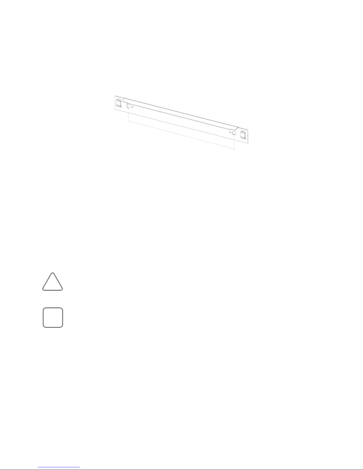
Figure 7 Mounting Bracket (dimensions in mm.)
Mounting procedure
1. Choose an adequate location and clearance
2. Drill holes for the mounting bracket in the wall (when required)
3. Drill holes for the xation in the wall (when required)
4. Mount the mounting bracket
5. Install the PowerRouter on the mounting bracket
6. Position the PowerRouter. See gure 5 (Mounting holes)
i
!
caution
400

15
6 Wiring
This chapter is intended for installers
This section provides step-by-step procedures and other information required for wir-
ing the PowerRouter to the PV array and the utility grid. To complete the installation
in a safe and efcient manner follow the steps in the order that they appear.
The AC input and AC output circuits are isolated from the enclosure and
system grounding.
Read all of the instructions, cautions, and warnings on the PowerRouter,
the PV array and this installation guide before connecting or
operating the PowerRouter.
Connect the wires that carry the AC voltage from the PowerRouter to the
utility grid and no-break load and the wires that carry the DC voltage from
the PV array to the PowerRouter in the order described in the procedures
in this section. Deviating from these procedures could
expose you to lethal voltage that can cause serious injury.
Turn OFF all breakers and switches in the PV system before connecting
any wires to or disconnecting any wires from the PowerRouter.
AC Grounding
Connect the PowerRouter to the AC ground from the utility via the ground
terminal (PE)
PV Grounding
Check local regulations.
DC Grounding Electrode Conductor
A DC grounding electrode conductor may be required by the local
authorities.
Figure 8 PowerRouter fully disconnected
i
!
caution

16
Bypass switch
Bypass switches are crucial components with which the PowerRouter supports critical
load situations. (The PowerRouter acts as an UPS system)
The bypass switch allows you to switch off the PowerRouter for maintenance, without
cutting power to the load. When the switch is activated, the mains supply is
redirected away from the PowerRouter, and directly to the load. The PowerRouter can
then be serviced and any maintenance work can be carried out without disturbing
the load. Once the PowerRouter is ready to be switched back on, the bypass switch is
deactivated and the supply is redirected back to the PowerRouter; the load receives
the high quality PowerRouter supply again.
The Bypass switch is an optional component and should be obtained and installed
separately.
Figure 9 PowerRouter bypassed
De-energize all energy sources before connecting the PowerRouter. (see also the
schematic in gure 8)
1. Connect AC wiring (Load / Grid)
2. Connect PV wiring (Solar)
3. Connect battery wiring
4. Switch ON DC-switches (Battery / Solar)
Turn OFF all AC switches before disconnecting the PowerRouter.
The DC system should always be disconnected before the AC system.
After the PowerRouter is de-energized, disconnect the wiring.
1. Switch OFF DC-switches (Solar / Battery)
2. Switch OFF AC-switches (Grid / Load)
3. Disconnect PV wiring (Solar)
4. Disconnect AC wiring (Grid / Load)
Connect or disconnect the wires to the PowerRouter in the following order:
Sequence of connecting and disconnecting
!
warning

17
6.1 Wiring AC Connections
Connect the wires that carry the AC voltage from the PowerRouter to the
utility grid in the order described in this procedure. Deviating from this
procedure could expose you to high voltages that can cause serious injury
and/or death.
Figure 10 AC connection schematic
This section describes the AC connections of the PowerRouter to the utility grid and
the load.
breaker box
!
warning

18
Connecting the wires to the PowerRouter terminal blocks.
Use 2.5 mm² wires minimal.
1. Turn OFF the main breaker in the main utility breaker box.
2. Connect the AC Grid/Utility ground wire to the AC Grid/Utility terminal
labeled
3. Connect the AC Grid/Utility L wire to the AC Grid/Utility terminal labeled L
4. Connect the AC Grid/Utility N wire to the AC Grid/Utility terminal labeled N
5. Connect the AC Line Out ground wire to the AC Line Out terminal labeled
6. Connect the AC Line Out L wire to the AC Line Out terminal labeled L
7. Connect the AC Line Out N wire to the AC Line Out terminal labeled N
8. Tighten strain reliefs.
Verify that all connections are correctly wired and properly torqued.
(min. 1.2 Nm, max. 1.5 Nm)
Figure 11 AC Connection terminals
Contacts need to be free of any mechanical strain.
AC Grid/Utility AC Line Out
NNL
L
AC Grid/Utility AC Line Out
!
caution

19
6.2 Wiring Solar connections
Connecting the PV string connectors to the PV terminals.
Connect 1 or 2 strings to the PV terminals using mating MC4 connectors.
Model PR30S only has 1 PV terminal.
This section describes the connection of the solar panels to the PowerRouter.
Figure 12 Solar connection scheme.
Internal PV-switch is only available in the PR50S with part no. 9560947, PR37S with
part no. 9561145 and PR30SBwith part no. 9561188
PV Connection
terminals (1 string)
Negative (-)
PV String connector
Positive (+)
PV String connector
Figure 13 Solar connection (gure shows PR50S and PR37S type)

20
All electrical installations must be done in accordance with all local
electrical regulations.
Use copper wire for all DC wiring connections to the PowerRouter. Volt-
age drop and other considerations may dictate that higher diameter wires
be used. Use only solid or stranded wire but not ne stranded wire.
An external DC disconnect (switch or terminal) for the PowerRouter must
have a minimum rating of 600 V DC and 15 A continuous.
Serial fusing may be required depending on the type of PV module and
conguration used in the system.
Figure 14 do not connect 1 string to both PV terminals simultaneous
The PowerRouter models are provided with 2 independant inputs, there for
not connect 1 PV-string on both PV terminals simultaneously
i
!
warning
!
warning
Other manuals for PowerRouter PR50S
1
This manual suits for next models
2
Table of contents
Other Nedap Inverter manuals


Popular Inverter manuals by other brands

Steren
Steren INV-300 user manual

Krieger
Krieger KRP150 instruction manual

Victron energy
Victron energy Phoenix Inverter Compact 12/800/35 User and installation manual

Beretta
Beretta Solar module 50 operating manual

Studer
Studer COMPACT C 1600-12 User's and installer's manual

Statpower
Statpower Portawattz 400 Installation & operation guide


