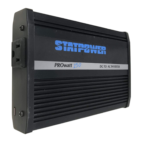
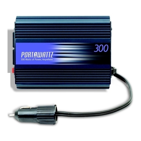
Statpower Portawattz 400 Original operating instructions

Tel: 604.420.1585
(toll-free) 1.800.670.0707
Fax: 604.420.1591
(toll-free) 1.800.994.7828
Web: www.xantrex.com
445-011 1-01-01 Printed in China

About Xantrex
Xantrex Technology Inc. is a world-leading supplier of advanced power electronics with
a product line that ranges from 50 Watt mobile units to MW utility-scale or stand-
alone systems for wind, solar, batteries, fuel cells, microturbines and backup power
applications. Xantrex products include inverters, battery chargers, programmable
power supplies, and variable speed drives that convert, supply, control, clean and
distribute electrical power.
Trademarks
PORTAWATTZ, TRUECHARGE and xPower are trademarks and PROsine and
Statpower are registered trademarks of Xantrex International. Xantrex is a registered
trademark of Xantrex Technology Inc.
© 200 Xantrex International. All rights reserved.
Notice of Copyright
PORTAWATTZ 400 Installation & Operations Guide © January 200 Xantrex
International.
Disclaimer
While every precaution has been taken to ensure the accuracy of the contents of this
guide, Xantrex International assumes no responsibility for errors or omissions. Note as
well that specifications and product functionality may change without notice.
Date and Revision
January 200 , Revision
Part Number
445-0 -0 -0
Contact nformation
Tel: 604.420. 585
(toll-free) .800.670.0707
Fax: 604.420. 59
(toll-free) .800.994.7828
Email: [email protected]
Web: www.xantrex.com

Contents
1 Introduction .................................... 1
2 Safety First .................................. 2
3 Quick Reference............................... 4
3.1 Overview .................................................. 4
3.2 Operating 115 VAC Products ........................ 5
4 Design Features ............................... 6
4.1 Switchmode Power Conversion Techno ogy .... 6
4.2 High Surge Power Capabi ity ........................ 6
4.3 Safety Features .......................................... 6
5 Installation uidelines ..................... 7
5.1 Se ecting a Suitab e Location ....................... 7
5.2 Using the DC Cab e - P ug ........................... 7
5.3 Using the DC Cab e-C ips ............................. 8
5.4 Permanent Insta ation ................................ 9
6 Battery Selection and Charging ...... 13
6.1 Battery Sizing (Genera Information) ............ 13
6.2 Estimating Battery Requirements ................ 14
6.3 Important Information About Batteries ......... 16
6.4 Battery Charging ....................................... 17
7 Operating 115 Volt AC Products and
Equipment ..................................... 18
7.1 Genera Information ................................... 18
7.2 Interference with E ectronic Equipment ........ 18

8 Using the PORTAWATTZ 400 .......... 20
8.1 Indicators and Contro s .............................. 20
8.2 Inverter Operation ..................................... 20
9 Troubleshooting ............................. 22
10 Limited Warranty and Performance
uarantee (USA and Canada Only) ........ 24
11 Service Out of Warranty ................. 27
12 Specifications ................................ 28
13 Other Products from Xantrex ......... 29

1
1 Introduction
Thank you for purchasing the PORTAWATTZ 400 Power Inverter.
The PORTAWATTZ 400 is part of an advanced fa ily of high
perfor ance power inverters fro Xantrex, the leader in the field of
high frequency inverter design. Fro the 12-Volt outlet in your
vehicle or boat, or directly fro a dedicated 12-Volt battery, the
PORTAWATTZ 400 will efficiently and reliably power a wide variety
of household AC products, such as TVs, co puters, co pact
fluorescent lights, s all power tools (3.5 A ps or less), and any
ore. The PORTAWATTZ 400 e ploys reliable solid state power
electronics for years of safe, trouble-free operation. It includes a
built-in cooling fan and auto atic safety onitoring circuitry to
protect the inverter, and your battery, fro inadvertent overload
conditions.
Read this guide before installing or using the PORTAWATTZ 400
and save it for future reference.
The following ain topics are covered in this guide:
·I portant safety infor ation
·Installation and operating instructions
·Warranty and service infor ation

2
2 Safety First
Incorrect installation or isuse of the PORTAWATTZ 400 ay result
in danger to the user or hazardous conditions. We urge you to pay
special attention to all CAUTIO and WAR I G state ents.
CAUTIO state ents identify conditions or practices that ay
result in da age to the PORTAWATTZ 400 or to other equip ent.
WAR I G state ents identify conditions that ay result in
personal injury or loss of life.
WARNING! Shock hazard. Keep away from children.
·The PORTAWATTZ 400 genera es he same po en ially le hal
AC power as a normal household wall ou le . Trea i wi h
he same respec ha you would any AC ou le .
·Do no inser foreign objec s in o he PORTAWATTZ 400s
AC ou le s, fan or ven openings.
·Do no expose he PORTAWATTZ 400 o wa er, rain, snow
or spray.
·Do no , under any circums ances, connec he
PORTAWATTZ 400s AC recep acles o u ili y power AC
dis ribu ion wiring.
WARNING! Hea ed surface.
·The PORTAWATTZ 400s housing may become
uncomfor ably warm, reaching 140°F (60°C) under
ex ended high power opera ion. Ensure ha a leas 2
inches (5 cm) of air space is main ained on all sides of he
PORTAWATTZ 400. During opera ion, keep away from
ma erials ha may be affec ed by high empera ures.
WARNING! Explosion hazard.
·Do no use he PORTAWATTZ 400 in he presence of
flammable fumes or gases, such as in he bilge of a
gasoline powered boa , or near propane anks. Do no use
he PORTAWATTZ 400 in an enclosure con aining
au omo ive- ype, lead-acid ba eries. These ba eries,
unlike sealed ba eries, ven explosive hydrogen gas, which
can be igni ed by sparks from elec rical connec ions.
·When working on elec rical equipmen always ensure
someone is nearby o help you in an emergency.

3
CAUTION!
·Do no connec live AC power o he PORTAWATTZ 400s AC
ou le s. The inver er will be damaged even if i is swi ched
OFF.
·Do no connec any AC load, which has i s neu ral conduc or
connec ed o ground, o he PORTAWATTZ 400.
·Do no expose he PORTAWATTZ 400 o empera ures
exceeding 104°F (40°C).
CAUTION! Do no use he PORTAWATTZ 400 wi h he
following equipmen :
·Small ba ery opera ed produc s such as rechargeable
flashligh s, some rechargeable shavers, and nigh -ligh s ha
are plugged direc ly in o an AC recep acle o recharge.
·Cer ain ba ery chargers for ba ery packs used in hand
powered ools. These chargers will have warning labels
s a ing ha dangerous vol ages are presen a he chargers
ba ery erminals.

4
3 Quick Reference
3.1 Overview
These basic instructions are intended to provide a brief overview of
the PORTAWATTZ 400s key features. For co plete infor ation
about the PORTAWATTZ 400, it is i portant to read this anual
fully. Figure 1 below shows the PORTAWATTZ 400s key features
and accessories.
Figure 1 - Key Features

5
3.2 Operating 115 VAC Products
1. After proper installation and connection to a 12-Volt battery, the
PORTAWATTZ 400 can be used to power products rated at 400
Watts or less (see Section 5).
2. To supply power to the AC outlets, turn the ON/OFF Switch ON.
The green POWER light indicates AC power is available.
3. Plug the AC products you wish to operate into the AC outlet(s)
and switch the on, one at a ti e.
4. In the event of an overload, low battery voltage or overheating, the
PORTAWATTZ 400 will auto atically shut down (see Section 9).

6
4 Design Features
4.1 Switchmode Power Conversion
Techno ogy
The PORTAWATTZ 400 e ploys advanced high frequency
switch ode power conversion circuitry. This results in a s aller,
lighter, ore efficient and quieter inverter.
4.2 High Surge Power Capabi ity
High perfor ance Power FETs (Field Effect Transistors) are
incorporated into a highly advanced circuit design to provide
outstanding high surge capability.
4.3 Safety Features
These advanced safety features are built into the PORTAWATTZ
400:
·Electronic overload protection with auto atic shutdown.
·Built-in internal backup DC fuse provides added safety.
·Low battery voltage warning followed by auto atic shutdown.
·Over te perature protection with auto atic shutdown.
·High input voltage protection with auto atic shutdown.
·Output short circuit protection.
·Manual reset eli inates unexpected restarting.

7
5 Installation Guidelines
5.1 Se ecting a Suitab e Location
For safe and opti u perfor ance, install the PORTAWATTZ 400 in
a location that is
Dry. Do not expose to water drip or spray.
Cool. Operate only in a bient te peratures between 32°F (0°C)
and 104°F (40°C). Keep away fro furnace heating vents or other
heat producing equip ent.
Well ventilated. Allow at least 2 inches (5 c ) clearance above and
on all sides of the PORTAWATTZ 400 for proper cooling.
Safe. Do not install PORTAWATTZ 400 in a co part ent with
batteries or fla able liquids, such as gasoline, or explosive
vapors.
Clean and free of dust and dirt. This is especially i portant
when the PORTAWATTZ 400 is used in a work environ ent, such
as a obile service vehicle. Metal dust fro key cutting achines
or fro grinding other types of etals can da age the
PORTAWATTZ 400 if it gets inside the housing (will also void
your warranty).
Relatively close to the battery source (when installed
per anently). This will ini ize the cable length fro the battery
to the inverter. It is better to run an extension cord fro the AC
outlets of the inverter to your product, than add additional cable
length fro the battery to the DC ter inals.
WARNING: To preven overhea ing and he po en ial for fire,
do no cover or obs ruc he ven ila ion holes or fan opening
on he PORTAWATTZ 400.
WARNING: The PORTAWATTZ 400 con ains componen s,
which may produce arcs or sparks. To preven fire or explosion,
do no ins all in compar men s where ba eries, flammable
liquids, or explosive vapors may be presen , or in loca ions
ha require igni ion pro ec ed equipmen .
5.2 Using the DC Cab e - P ug
Due to li itations in the co on 12-Volt outlet in a vehicle or boat,
the PORTAWATTZ 400 should only be used to supply AC power to
products that require 150 Watts (about 1.3 A ps) or less. If your
application requires ore than 150 Watts (but less than 400 Watts
continuous) or has a high start-up surge, see Section 5.3.

8
1. Attach the ring type connector arked with red to the positive
(+) DC ter inal on the PORTAWATTZ 400 and attach the
ring connector arked with black to the negative (-) DC
ter inal.
CAUTION! A reverse polari y connec ion (posi ive o nega ive)
may damage he PORTAWATTZ 400. Damage caused by a
reverse polari y connec ion is no covered under warran y.
2. Tighten the nut on each DC ter inal by hand until it is snug.
Do not over tighten.
3. Insert the plug of this cable into the 12-Volt outlet and switch
the unit ON. See Section 9 if the PORTAWATTZ 400 does
not operate properly after being connected.
4. When the PORTAWATTZ 400 is not in use, unplug it fro
the 12-Volt outlet to prevent slight discharge of the battery.
5.3 Using the DC Cab e-C ips
By directly connecting the PORTAWATTZ 400 to a 12-Volt battery
with the DC Cable-Clips, you can operate products with power
require ents up to 400 Watts continuous. If you want to
per anently connect the PORTAWATTZ 400 to a battery, refer to
Section 5.4.
1. Follow steps 1 and 2 above (Section 5.2) to attach the ring
type connectors.
2. Attach the black negative clip to the negative (-) battery
ter inal
3. Attach the red positive clip to the positive (+) battery ter inal.
Make sure both clips are securely connected to the battery
ter inals, as a loose connection will cause excessive voltage
drop and ay cause the cables to overheat resulting in
equip ent da age or fire.
4. Switch the PORTAWATTZ 400 ON. See Section 9 if the
PORTAWATTZ 400 does not operate properly after being
connected.
5. When the PORTAWATTZ 400 is not in use, disconnect the
DC Cable-Clips fro the battery. This will prevent slight
discharge of the battery.

9
5.4 Permanent Insta ation
A per anent installation is highly reco ended if you will be using
your PORTAWATTZ 400 frequently to power electrical products of
ore than 150 Watts. Read this entire section co pletely before
purchasing any supplies or beginning the installation.
DC Cable Selection and Preparation
Correct cable size and wiring is very i portant for safe operation and
axi u perfor ance of the PORTAWATTZ 400. Because the
PORTAWATTZ 400 is designed for low voltage, high current input,
low resistance cable fro the battery to the DC ter inals is needed to
deliver the axi u a ount of usable energy. Undersized cable
will di inish battery and inverter perfor ance.
Use copper wire rather than alu inu . Alu inu wire has 1/3 ore
resistance than copper wire of the sa e size and good, low resistance
connections are ore difficult to achieve.
For cable runs between the battery and inverter of 4 ft. or less use #8
AWG copper cable. For wire runs of 4 ft. to 12 ft. use #6 AWG
copper cable. The insulation on the cable should be rated at 90ºC
( ini u ). Using undersized cable, or when the battery to inverter
run is greater than 12 ft., ay result in excessive voltage drop
between the battery and PORTAWATTZ 400 and cause the inverter to
pre aturely shut down.
As a general rule, select a cable size that is heavier than
the ini u required for your installation. A heavier
cable will reduce the voltage drop fro the battery to the
inverter and provide greater run ti e.
Securely attach a M5 or larger ring type ter inal to the end of each
cable that will be connected to the PORTAWATTZ 400s DC
ter inals. The end of each cable that is connected to the battery ust
be fitted with a ter inal ring that is secured to the post on the battery.
A solid, low resistance connection to the battery is essential for
proper operation of the PORTAWATTZ 400.
IMPORTANT! Ins alla ion of a 50 Amp Class T fuse or 50 Amp
circui breaker on he cable ha runs from he posi ive DC Inpu
Terminal on he PORTAWATTZ 400 o he posi ive ba ery pos
is recommended. Ins all he fuse or circui breaker near he
end of he cable ha is connec ed o he ba ery, following
ins alla ion ins ruc ions provided by i s manufac urer. Make sure
he fuse or circui breaker selec ed has an in errup ra ing of a
leas 10 imes he amp hour ra ing of he ba ery (or ba eries).

10
Connecting the PORTAWATTZ 400 to a Battery
Follow the steps below to connect the PORTAWATTZ 400 to a
battery. Read the CAUTIO and WAR I G state ents that apply
to this section carefully. If you are unsure how to ake a safe
connection, contact Xantrex Custo er Service for assistance. Figure
2 illustrates a basic connection to a 12-Volt battery.
1. Turn the ON/OFF Switch on the PORTAWATTZ 400 to OFF.
If you are using a battery selector switch, turn it off as well. If
you installed a circuit breaker (or a fuse) on the positive cable,
switch it to OFF (or re ove the fuse).
Figure 2 - Connection to a Battery

11
2. Connect the #8 or #6 cables to the DC Input Ter inals on the
end of the PORTAWATTZ 400. The positive cable is
connected to the red (+) ter inal and the negative cable is
connected to the black (-) ter inal. Secure each cable to its
respective ter inal by tightening the nut on the ter inal post.
Tighten to the reco ended torque setting of 10 lbin.
3. Connect the negative cable fro the PORTAWATTZ 400 to
the negative battery post and fasten securely.
4. Check the cable which is not yet connected to the battery and
confir that it is connected to a circuit breaker or fuse, which
in turn is connected to the positive (+) DC Input Ter inal on
the PORTAWATTZ 400.
5. Check the post on the battery that does not have a cable
attached to it and confir that it is the positive battery
ter inal.
6. Connect the positive cable fro the PORTAWATTZ 400,
which has the in-line circuit breaker or fuse, to the positive
battery post and fasten securely. If you are using a battery
selector switch, connect the positive cable fro the
PORTAWATTZ 400 to the positive ter inal and fasten
securely.
7. If a circuit breaker was installed on the positive cable, switch
it ON, or insert the fuse. If a battery selector switch is used,
select a setting that allows current to flow fro one of the
batteries to the PORTAWATTZ 400. Current (12 volts)
should now be flowing fro the battery to the PORTAWATTZ
400.
8. Set the ON/OFF Switch on the PORTAWATTZ 400 to the ON
position. The green POWER indicator should be illu inated
and 115 Volt AC power available fro the two outlets. If not,
or if the red FAULT indicator is illu inated, check the battery
and wiring to the PORTAWATTZ 400.
WARNING! Connec ions ha are no igh may crea e a
hazard. Periodically check all cable connec ions and igh en
as required. This is especially impor an if he PORTAWATTZ
400 is ins alled in a vehicle or boa . The vibra ion of he inver er,
cables, and ba ery in hese environmen s may cause
connec ions o loosen.

12
WARNING! Connec ions o ba ery pos s mus be made wi h
permanen connec ors ha provide a reliable, low resis ance
connec ion. Temporary alliga or ype clips are no
recommended for permanen ins alla ion. Loose connec ors
will cause excessive vol age drop and may cause he cables o
overhead resul ing in equipmen damage or fire. Clean he
permanen connec ors regularly and preven corrosion by using
an insula ing spray coa ing.
WARNING! Do no connec he PORTAWATTZ 400 o a
ba ery if here are flammable fumes or liquids presen .
Explosion or fire may resul . Remove any flammable ma erials
and ven ila e he area of any vapors before making a connec ion
o he ba ery.
CAUTION! A reverse polari y connec ion (posi ive o nega ive)
will open in ernal fuses in he PORTAWATTZ 400 and may
damage he uni . Damage caused by a reverse polari y
connec ion is no covered under warran y.

13
6 attery Selection and
Charging
6.1 Battery Sizing (Genera Information)
The battery or batteries selected should be deter ined based on the
applications you plan on running with the PORTAWATTZ 400.
These are two co on battery types:
Automotive Lead Acid These batteries are designed to deliver a
large a ount of current for a short period of ti e and are typically
located in the engine co part ent of a car or truck. This design
works well for starting the engine of a vehicle.
Only a s all portion of the batterys capacity is used for starting the
engine, and once started, the vehicles alternator quickly recharges
the battery. Unlike deep cycle type batteries, auto otive lead acid
batteries are not designed for repeated cycles of full discharge and
recharge. For this reason, we reco end using this type of battery
when ost of your applications are 300 Watts or less and operating
ti es are relatively short (1-2 hours), or if your vehicles engine is
kept running when the inverter is used.
Deep Cycle Lead Acid These batteries are designed for repeated
cycles of full discharge and recharge and are often used in RVs,
boats, and golf carts. Select this type of battery when ost of your
applications require higher power ( ore than 300 Watts), your use of
the inverter is frequent, or when you run applications for extended
periods of ti e ( ore than 2 hours).
When a deep cycle battery is used in a vehicle, we reco end
installing a battery isolator to prevent the auxiliary deep cycle battery
fro discharging the vehicles starting battery. The isolator
auto atically directs the current fro the vehicles alternator to the
battery requiring a charge. Isolators can usually be purchased at auto
parts, arine, or RV stores/dealerships.
CAUTION! Connec PORTAWATTZ 400 only o ba eries wi h
a 12-Vol nominal ou pu . A ba ery wi h 6-Vol nominal ou pu
will no supply enough vol age and a ba ery wi h 24-Vol
nominal ou pu will damage he inver er.
Just as i portant as the type of battery selected is its size or capacity.
A large battery will extend running ti e and ensure that your
PORTAWATTZ 400 delivers its full rated surge. For ost
applications, batteries fro 50Ah (120 reserve inutes) to 400Ah
(1800 reserve inutes) will be sufficient, but depending on your

14
needs, a battery bank with greater capacity ay be appropriate. The
ini u battery size reco ended is 50Ah.
A nu ber of different standards are used to rate battery energy
storage capacity. Auto otive and arine starting batteries are
nor ally rated in cranking a ps. This is not a relevant rating for
continuous loads like an inverter.
Deep-cycle batteries use a ore suitable rating syste , either a p-
hours (Ah) or reserve capacity in inutes. Battery reserve
capacity is a easure of how long a battery can deliver a certain
a ount of current - usually 25 A ps. For exa ple, a battery with a
reserve capacity of 180 inutes can deliver 25 A ps for 180 inutes
before it is co pletely discharged.
A p-hour capacity is a easure of how any a ps a battery can
deliver for a specified length of ti e - usually 20 hours. For
exa ple, a typical arine or RV battery rated for 100Ah can deliver
5 A ps for 20 hours (5A x 20 hours = 100Ah). This sa e battery
can deliver a higher or lower current for less or ore ti e, li ited
approxi ately by the 100Ah figure (e.g. 50A for 2 hours, or 200A for
1/2 hour), but usually the capacity figure given is only accurate at the
specified rate (20 hours).
6.2 Estimating Battery Requirements
To deter ine the proper battery size or battery bank, you need to
co pute the nu ber of a p-hours that will be used between
charging cycles. When the required a p-hours are known, size the
batteries at approxi ately twice this a ount. The expected a p-hour
require ents of each product to be used should be deter ined and
then added together; this total ultiplied by 2 is the reco ended
battery size.
Start with the na eplate ratings on your electrical products. If the
wattage is arked on the product, you can use that nu ber directly;
otherwise, ultiply the arked voltage and a perage: WATTS =
VOLTS X AMPS. Once you know the AC wattage drawn fro the
inverter, ultiply that by the length of ti e the appliance will be used
to deter ine the energy the load will require: WATT-HOURS =
WATTS X HOURS. You can then convert this to an esti ate of the
battery a p-hours that the products require:
SRUOH-PMAYRETTAB
DESU
=
SRUOH-TTAWCA
01

15
For exa ple, a 100W light bulb that is used for 4 hours will use 400
Watt-hours (Wh) and the inverter will consu e approxi ately 40Ah
fro a 12V battery.
Another useful rule of thu b is that the current drawn fro the
battery can be esti ated fro the AC output watts by using a factor
of 10. For exa ple, when running a 400W power drill, the inverter
will draw approxi ately 40A (400 divided by 10) fro a 12V battery.
Battery Sizing E ample
The following exa ple shows how battery size is calculated,
assu ing the battery can be recharged after two days:
This exa ple illustrates how quickly your battery needs can escalate.
To reduce the required battery size, you can either conserve energy by
eli inating or reducing the use of so e loads, or re-charge ore
frequently.
When sizing your battery, be conservative and resist the te ptation to
skip the last step of this calculation ( ultiply by 2). More capacity is
better because you gain ore reserve capacity, and therefore can
better handle large loads and surge loads, and your battery wont be
discharged as deeply.
lacirtcelE
stcudorP
rewoP
noitpmusnoC
)A(
gnitarepO
repemiT
yaD
)B(
-ttaWyliaD
dedeeNsruoH
stcudorProf
)BxA=(
obmoCRCV/VTW002sruoH2W004
naFelbaTW05sruoH4W002
pmaLelbaTW06sruoH4W042
daoLCAfosruoH-ttaWyliaDlatoTW048
segraCneewteBsyaDforebmuNx2
neewteBdaoLCAfosruoH-ttaWlatoT=
segraC
W0861
segraCneewteBdesUAyrettaB
)01ybdediviD(
A861
hAniezi)knaB(yrettaBdednemmoceR
)2ybylpitlum(
hA633
Table 1 - Battery Sizing Example

16
Battery life is directly dependent on how deeply the battery
is discharged; the deeper the discharge, the shorter the
battery life.
E amples of Operating Times Based On Load
If you plan to use the PORTAWATTZ 400 with a specific product, the
chart below (table 2) provides approxi ate operating ti es based on
battery size. These operating ti es assu e the battery is fully
discharged, so be certain to purchase double the battery size shown if
you will frequently operate the product for the ti e period stated.
6.3 Important Information About Batteries
These are points to keep in ind when using or installing a battery:
·With the exception of sealed, gel cell batteries, lead acid batteries
e it hydrogen and oxygen gases, and sulfuric acid fu es when
recharging. Make sure the battery co part ent is vented to prevent
accu ulation of gases and fu es and do not install electronic
equip ent in these areas. Also, do not s oke or have an open
fla e when working around batteries.
·The capacity of lead acid batteries is te perature sensitive. The
stated capacity of a battery assu es the air te perature is 77ºF
(25ºC). When the air te perature drops to 0ºF (20ºC), the actual
a p-hour capacity will be about one-half of the batterys rated
capacity.
·Do not leave batteries in a discharged state for ore than two
days. Batteries left discharged too long undergo a che ical process
called sulfation, which can per anently da age the battery.
·Batteries self-discharge over ti e, even when they are not used.
Recharge your battery every 3 onths to aintain its rated capacity.
Store batteries at roo te perature; batteries subjected to high
retrevnI
tuptuO
rewoP
)sttaW(
lacipyT
daoL
PMAV21
warD
morF
yrettaB
eziyrettaB
puorGICB
ezi
FN22 42 72 D8 s'D8lauD
evreseR
yticapaC .nim09.nim041.nim081.nim004.nim009
sruoHpmA
05 57 001 002 004
001
VTroloC"9101
gnitarepO
emiT
.srH4.srH6.srH01.srH02.srH04
002
retupmoC
metsyS 02
gnitarepO
emiT
.srH2.srH3.srH5.4.srH01.srH02
003
rednelB52
gnitarepO
emiT
.srH3.1.srH2.2.srH3.srH6.srH21
004
llirDrewoP53
gnitarepO
emiT
.rH1.srH5.1.srH2.srH5.4.srH01
dednemmoceRtoN=.R.N
Table 2 - Operating Times Based On oad
Table of contents
Other Statpower Inverter manuals
Popular Inverter manuals by other brands
Xinje
Xinje VB5N Series user manual
abora
abora aH72 SK Handbook

Hyundai
Hyundai N700E instruction manual
CUSTOM POWER DESIGN
CUSTOM POWER DESIGN Handy Mains Series quick start guide
ZIEHL-ABEGG
ZIEHL-ABEGG Icontrol FXDM Series operating instructions
Atlas Copco
Atlas Copco QAS 80 Pd S3A ESF instruction manual
Selectronic
Selectronic LD200-12 operating manual
meibes
meibes Solar station S Technical information for installation and operation

HNC Electric
HNC Electric HV100 Series user manual

Voltec Pro
Voltec Pro Pure Sine Wave owner's manual
SMA
SMA SMC 5000A installation guide

Kaco
Kaco Powador 3200 operating instructions

