Nedap PowerRouter Instruction Manual
1
Before operating the PowerRouter, you may initialize the PowerRouter by using the
PowerRouter software installation tool. The PowerRouter software installation tool helps
you to initialize the PowerRouter but also allows you to make advanced settings and update
the PowerRouter firmware, if applicable.
To help you properly install the PowerRouter via the installation tool, we have compiled this helpful application
guideline. This guideline explains the options and guides you through the procedures for using the installation tool.
Following these steps will ensure proper installation and allow you to quickly and easily connect the PowerRouter
with the correct settings.
Prior to start-up
Before you can use the installation tool you must install the software installation tool on your computer. You may
download the installation tool from the website: www.PowerRouter.com (you will need your login details for this
website). The software installation tool can be used to congure PowerRouters with rmware version 4.0 and
higher. If a PowerRouter with an older rmware version is detected, the installation tool will only allow you to
update the PowerRouter. The installation tool already includes the latest available rmware version so no additional
downloads are required.
System requirements
The installation tool is compatible with the following operating systems:
Operating systems:
> Windows XP (service pack 3)
> Windows Vista
> Windows 7
PowerRouter application guideline
Software installation tool - version 3.0
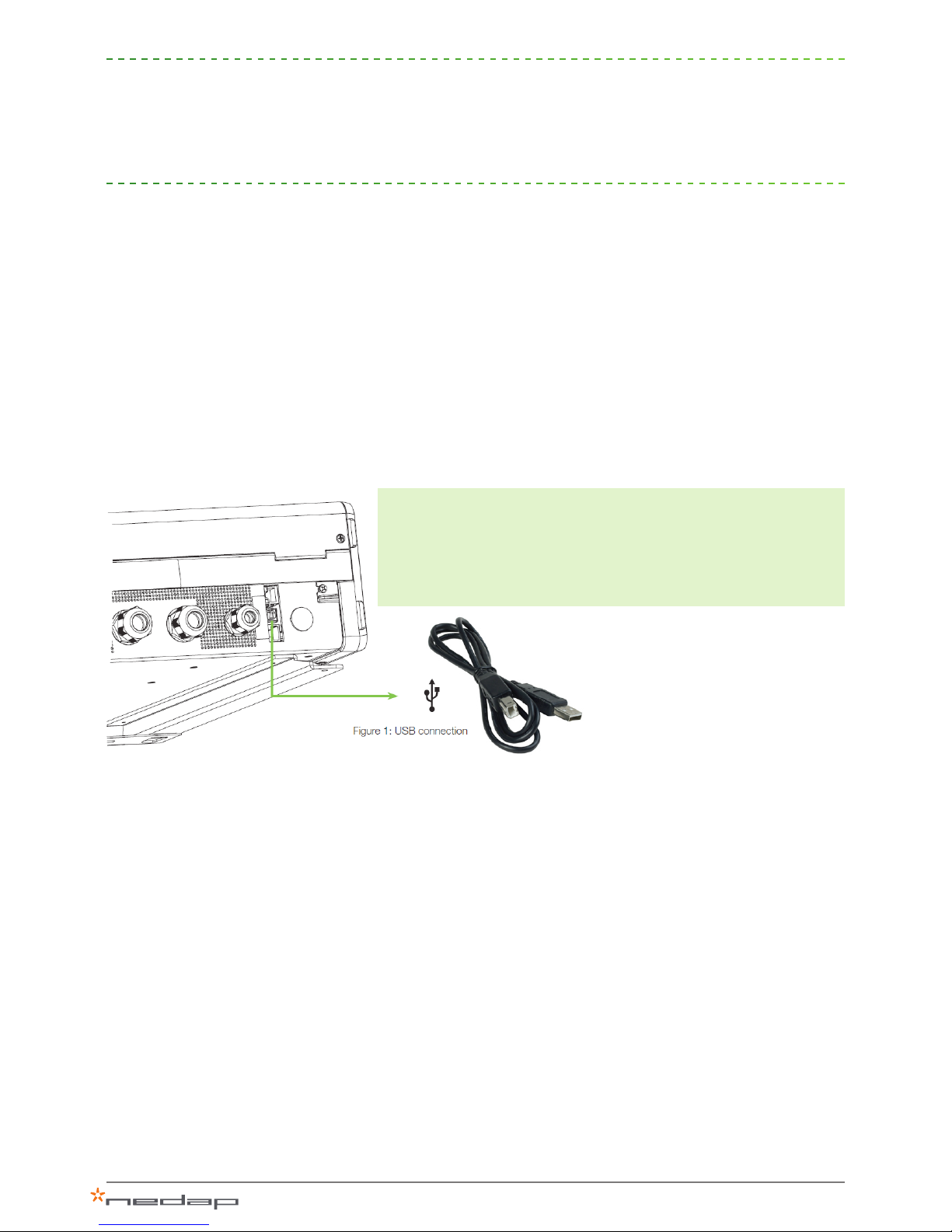
The PowerRouter must be connected to a USB port on your PC /
laptop via a standard USB cable (printer cable) (g. 1).
Minimum requirements for processor and other hardware:
> Pentium III 800 MHz or equivalent
> 128 MB RAM
> 200 MB free hard disk space
> Resolution of 1024 x 768 pixels with 256 colours

2
Installation - basic settings
To install the installation tool, start the "setup_installtool.exe" file which you have to
download from the PowerRouter site and follow the instructions.
Note: You can click the “?” icon in the upper-right corner at any time for help.
1.1 Select language
When you start the installation tool the rst time you will be asked
for your language. Select the preferred language and continue.
1.2 Detect PowerRouter
You can congure a new system using the installation wizard. The
wizard automatically detects whether you are connected to a new
PowerRouter system. The wizard guides you through the minimal
required settings to get your PowerRouter operational.
1.3 Select scenario
This step indicates the pre congured scenario of the installed
PowerRouter. This allows you to verify if you have the correct
PowerRouter installed. There are 3 scenarios:
1. “Feed-in” scenario
2. “Backup” scenario
3. “Self-use scenario
Note: Only for specic systems it is allowed to change the
scenario.
1
Figure 2: Select language
Continue
Figure 3: Detect PowerRouter
Figure 4: Scenario
ContinueBack

3
1.4 Select country
Select the country in which the system will be installed.
Country-specic grid validation settings will be programmed
automatically, such as:
Anti-Islanding - Frequency - Voltage - AC values
1.5 Select display text & language
Congure the status parameters to be shown on the four lines
of the system display and the language of the display. Values
shown are the actual system display settings. Select the status
parameter to be shown on each line of the display via the drop-
down menu.
1.6 Select battery
Select and congure the connected battery. Select “not
congured” if you are installing a system without batteries
connected at the moment. When you install a battery, enter
capacity/max DOD (depth of discharge) and DOD self-use.
Capacity (C10)
Enter the capacity in Ah/C10. When no C10 rating (capacity value
of the battery discharged in 10 hours) is available, use the rating
which is closest to C10. The capacity can be found on the battery
itself or on the battery specication sheet.
Maximum depth of discharge (DOD) - backup
Enter the maximum depth of discharge allowed during a grid
failure. This denes the percentage of the battery capacity that
is used for backup purposes. For backup it is common to use as
much of the available battery capacity as possible, to increase the
available backup time. Deeply discharging a battery on a frequent
basis reduces its service life considerably. So if the installation
location is subject to frequent grid failures it is suggested that you
congure a lower maximum depth of discharge to increase the
battery service life (default is 100%).
Max depth of discharge (DOD) - self-use
Select the percentage of daily discharge of the battery to increase
self-consumption of your generated energy. The battery will be
discharged to this percentage on a daily basis. For lead-acid
batteries a maximum depth of discharge of 50% is advised. A
lower percentage will increase the service life of the batteries.
Figure 5: Country settting
ContinueBack
Figure 6: Parameters display
ContinueBack
Figure 7: Battery selection
ContinueBack Continue
Back

4
Dashboard
When all the basic settings have been made, press “Install”. The configuration will be
written to the PowerRouter and the system will reset to activate the configuration.
The main panel of the installation tool is a dashboard that
provides you information about the current status of the
PowerRouter. Advanced settings can be made via the drop-down
menu that opens when you hover over the word “Advanced” in the
upper-right corner.
Hover over the icons and a mouse-over status panel will appear
with additional information as explained below:
Grid
> Module status: shows the status of the AC module in the
system. Only intended for diagnostics during service.
> Grid voltage: shows the current grid voltage.
> Frequency: shows the current grid frequency.
> Grid Power: shows the output power of the grid module.
> 5 latest grid disconnection events
Solar
> Module status: shows the status of the system’s internal solar
module.
> Voltage and current of each solar string at this moment.
Local out
> Module status: shows the status of the system’s AC module.
> Voltage island mode: shows the current local out voltage.
> Frequency: shows the local out frequency.
> Local power: shows the actual load on local out.
Battery
> Module status: shows the status of the system’s internal
battery module.
> Battery type: shows battery type.
> Autonomy time: shows autonomy time at the current rate of
power consumption.
> State of charge: shows the current battery charge level, in
percent.
> Voltage: shows battery voltage (charging or discharging).
> Current: shows battery current (charging or discharging).
> Temperature: shows reading from battery temperature sensor
(should be mounted at positive battery clamp).
Internet
> MAC address: shows the system’s MAC address.
2
WeiterZurück
Figure 8: Dashboard
Advanced

5
Advanced settings
Via the advanced menu you can:
I. Change the system conguration via “Settings”
II. Restart the installation wizard via “Reinstall”
III. “Check the system for updates” (installation tool and rmware)
IV. “Update rmware”
V. Change the “Language” of the installation tool
I.
It is possible to congure each system feature in order to optimize
the installation. Settings that have been changed are marked
with an orange star. Changed settings are only applied to the
system after pressing “install and reset”. This will write the
changed settings to the system and reset it to activate the new
conguration.
Display - conguring the system display
Backlight
When auto mode is selected the display will switch off after it has
not been used for two minutes. When always on is selected the
display will never switch off.
Display
Congure the status parameters to be shown on the four lines
of the system display and the language of the display. Values
shown are the actual system display settings. Select the status
parameter to be shown on each line of the display via the drop-
down menu.
Language
Select the system language. The menu and display interface
will be set to the language you choose here. You will not set any
country settings. The display language can be set to:
> English
> Dutch
> German
> French
> Italian
3
Figure 9: Advanced menu
Figure 10: Settings
Advanced
Settings
Reinstall
Check for updates
Update rmware
Language
Settings
I.
II.
III.
IV.
V.

6
PowerRouter - conguring general system settings
Scenario
The scenario denes the intended use of the system. Only for
specic systems it is possible to change the scenario.
> In the “Feed-in” scenario the system will feed all its energy
back to the grid.
> In the “Backup” scenario the system will charge the batteries.
The surplus will be sent to the grid.
> In the “Self-use” scenario the system will rst send the
generated energy to the load and then to the battery. Any
surplus will be sent to the grid.
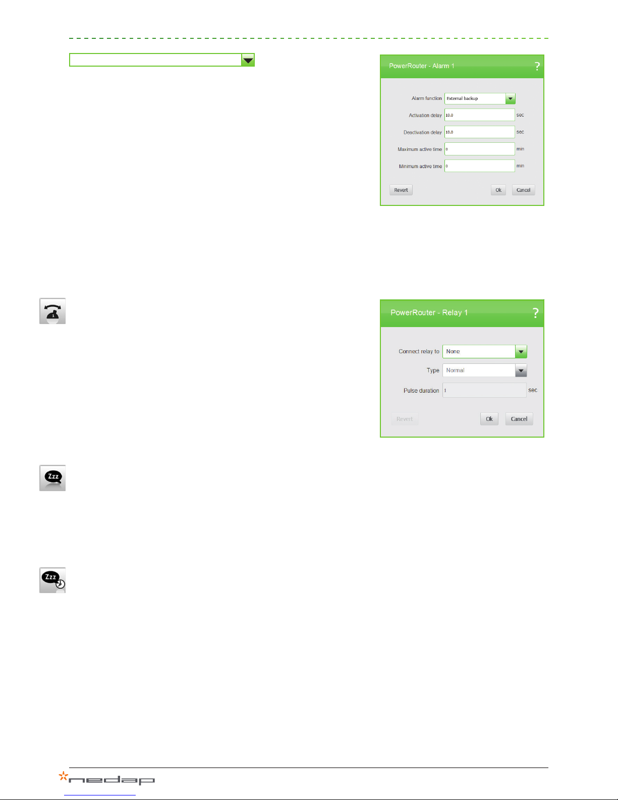
Alarm 1 / 2
Generates an alarm notication. This notication can be assigned
to a user-selectable relay. These alarms are based on selected
system conditions. To assign the alarm to a user-selectable relay,
please congure relay 1 or 2 via a separate conguration option.
The following system conditions are available:
None
Alarm is not used (default).
Grid voltage
Set trip level to activate the alarm based on the actual grid
voltage.
> Activate trip limit: when the grid voltage is outside this range,
the alarm will be activated.
> Deactivate trip limit: when the grid voltage is inside this range,
the alarm will be deactivated.
> Activation delay: delay time in seconds before the alarm will be
activated (between 0 and 100 seconds).
> Deactivation delay: delay time in seconds before the alarm will
be deactivated (between 0 and 100 seconds).
> Maximum active time: maximum time in minutes that the alarm
can be activated (between 0 – 720 minutes).
> Minimum active time: minimum time in minutes that the alarm
can be activated (between 0 – 720 minutes).
Figure 11: Alarm 1 / 2
Figure 12: Grid voltage

7
Battery state of charge
Set trip level to activate the relay based on the actual battery state
of charge (SOC):
> Activate alarm if SOC is below a given percent.
> Deactivate if SOC is above a given percent of state of charge.
> Activation delay: delay time in seconds before the alarm will be
activated (between 0 and 100 seconds).
> Deactivation delay: delay time in seconds before the alarm will
be deactivated (between 0 and 100 seconds).
> Maximum active time: maximum time in minutes that the alarm
can be activated (between 0 – 720 minutes).
> Minimum active time: minimum time in minutes that the alarm
can be activated (between 0 – 720 minutes).
Battery temperature
Set trip level to activate the relay based on the actual battery
temperature:
> Alarm temperature: set a value between 45 and 60 degrees
Celsius above which the alarm will be activated.
> Safe temperature: set a value between 30 and 50 degrees
Celsius under which the alarm will be deactivated.
> Activation delay: delay time in seconds before the alarm will be
activated (between 0 and 100 seconds).
> Deactivation delay: delay time in seconds before the alarm will
be deactivated (between 0 and 100 seconds).
> Maximum active time: maximum time in minutes that the alarm
can be activated (between 0 – 720 minutes).
> Minimum active time: minimum time in minutes that the alarm
can be activated (between 0 – 720 minutes).
Battery voltage
Set trip level to activate the relay based on the actual battery
voltage:
> Low voltage: set the low voltage under which the alarm will be
activated.
> Safe voltage: set the alarm deactivation voltage.
> Activation delay: delay time in seconds before the alarm will be
activated (between 0 and 100 seconds).
> Deactivation delay: delay time in seconds before the alarm will
be deactivated (between 0 and 100 seconds).
> Maximum active time: maximum time in minutes that the alarm
can be activated (between 0 – 720 minutes).
> Minimum active time: minimum time in minutes that the alarm
can be activated (between 0 – 720 minutes).
Figure 13: Battery state of charge
Figure 14: Battery temperature
Figure 15: Battery voltage

8
Grid connection
This setting will trip the relay in the event of a grid failure:
> Alarm on: choose the alarm to be activated when grid
connected or disconnected.
> Activation delay: delay time in seconds before the alarm will be
activated (between 0 and 100 seconds).
> Deactivation delay: delay time in seconds before the alarm will
be deactivated (between 0 and 100 seconds).
> Maximum active time: maximum time in minutes that the alarm
can be activated (between 0 – 720 minutes).
> Minimum active time: minimum time in minutes that the alarm
can be activated (between 0 – 720 minutes).
Load management
Select conditions to switch on or off additional loads:
> Connected load: dene how much power is connected as
additional load to be switched on, in watts.
> Activate on load support: activates if the percentage of the
dened power of the load is available as an energy surplus.
> Deactivate on load support: deactivates if the available surplus
is below a coverage of a % set between 20 and 200%.
> Activation delay: delay time in seconds before the alarm will be
activated (between 0 and 100 seconds).
> Deactivation delay: delay time in seconds before the alarm will
be deactivated (between 0 and 100 seconds).
> Maximum active time: maximum time in minutes that the alarm
can be activated (between 0 – 720 minutes).
> Minimum active time: minimum time in minutes that the alarm
can be activated (between 0 – 720 minutes).
To use the load management application this alarm must be linked
to a user-selectable relay.
Figure 16: Grid connection
Figure 17: Load management
9
External backup
Use this alarm for triggering the external backup relay. This
external relay is used to switch loads to the local out when the
grid connection fails.
> Activation delay: delay time in seconds before the alarm will be
activated (between 0 and 100 seconds).
> Deactivation delay: delay time in seconds before the alarm will
be deactivated. (between 0 and 100 seconds).
> Maximum active time: maximum time in minutes that the alarm
can be activated (between 0 – 720 minutes).
> Minimum active time: minimum time in minutes that the alarm
can be activated (between 0 – 720 minutes).
To use the external backup application this alarm must be linked
to a user-selectable relay.
Relay 1 / 2
When you have set alarm 1/2, you can then set the two user-
selectable relays (K201 and K202).
> Alarm: select alarm to activate this user-selectable relay.
> Set relay signal type
> Normal (default): user-selectable relay is activated when
switched on.
> Pulse: activates the user-selectable relay for a dened duration
of between 1 and 10 seconds when switched on, for example
a start signal or a short ringing signal.
Standby
When “standby allowed” is activated the system will go into
standby mode when there is no solar power or battery power
available. In standby mode the system consumes a minimum
amount of energy. Local out will also be without power in standby,
and no emergency power is available.
Standby timer
When “standby timer” is enabled you can set a time interval
during which the system is forced to remain in standby. Example:
The load during the night is very low, so the dissipation in the
system is high compared to the load that is compensated. In that
case you force the system into standby during that period.
Note: If a grid failure occurs while the system is in standby, the
system will switch to backup operation.
Figure 18: External backup
Figure 19: Relay 1 / 2

10
Grid - conguring grid related settings
Country
Select the country in which the system will be installed.
Country-specic grid validation settings will be programmed
automatically, such as:
Anti-islanding - Frequency - Voltage - AC values
Grid limits
When enabled, country specic settings can be overruled. This
is only allowed only with specic permission from the energy
contractor.
EEG 2012*
When enabled, the system complies with the EEG2012 regulations
(in Germany) by limiting its grid output power to 70% of nominal
power by default. The limitation can be optimized by entering the
installed solar power capacity. The system will then limit its AC
output to 70% of the installed solar power capacity.
VDE4105*
Here you can change the reactive power settings as required
by your local utility company, when deviating from the standard
VDE4105 curve.
*Note: This setting is only applicable when the PowerRouter is
installed in Germany.
Figure 20: Country
Figure 21: Grid limits
Figure 22: EEG2012
Figure 23: VDE4105

11
Dynamic feed-in limiter
Set the max. output power to the grid. With the external grid
sensor is connected, the power is limited at the point of feed-in,
otherwise it is limited to the output power of the inverter.
Battery - conguring battery specic settings
Note: Check the nal page of this document for the Nedap-
recommended battery settings.
Battery pack
Select and congure the connected battery. Select not congured
if you are installing a system without batteries. When you install a
battery, enter the capacity/max DOD.
> Capacity (C10): Enter the capacity in Ah/C10. When no C10
rating is available, take the rating which is closest to C10. The
capacity can be found on the battery itself or on the battery
specication sheet (capacity value of the battery discharged in
10 hours).
> Maximum depth of discharge (DOD): Enter the maximum
depth of discharge allowed during a grid failure. This denes
the percentage of the battery capacity that is used for backup
purposes. For backup it is common to use as much of the
available battery capacity as possible, to increase the available
backup time. Deeply discharging a battery on a frequent
basis reduces its service life considerably. So if the installation
location is subject to frequent grid failures it is suggested that
you congure a lower maximum depth of discharge to increase
the battery service life (default is 100%).
Note: Connecting the batteries in series does not increase the
number of Ah! The Ah of the individual batteries may only be
added together when the batteries are connected in parallel.
Figure 24: Dynamic feed-in limiter
Figure 25: Battery pack
12
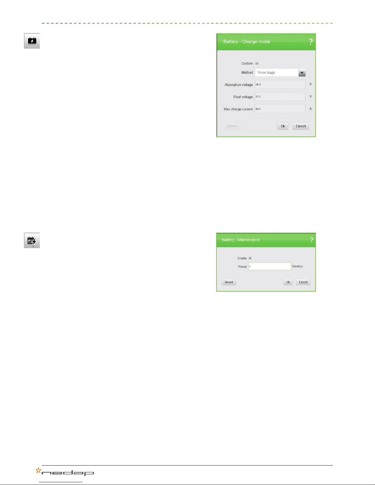
Charge mode
The three-stage charging mode is the default setting and is
recommended for most operations. The battery is charged in
three stages, which is a quick method of charging (when solar
power is available we want the system to store it rather than feed
it into the grid). The three stages are:
1. Bulk stage – charges the battery to 70-80% of its capacity at
maximum charging current and with increasing voltage.
2. Absorption stage – charges the battery to 85-90% of its
capacity at the absorption voltage.
3. Float stage – tops off the charge to 100% of the battery
capacity, with low current and oat voltage.
The current and voltage values you should enter here can be
found on the battery data sheet. For proper operation it is
essential that these values are set correctly. Incorrect settings can
damage the batteries!
At xed oat, the batteries are charged with a constant voltage.
This can be used in a backup application where batteries may be
charged over a long period of time.
Maintenance
During every charge/discharge cycle the SOC value (state of
charge) of a battery becomes less accurate. For good battery
management the system needs to calibrate 100% SOC with the
batteries fully charged on a regular basis. To optimize their service
life, batteries should also be protected against operation that
prevents them from becoming fully charged. During maintenance
charge the system will give priority to charging the batteries
with the solar power, and it can take a maximum three days to
fully charge the batteries. When an SOC of 100% is reached
the system will go in normal mode again. During winter mode,
maintenance charging will be performed. The default setting is
once every four weeks.
Figure 26: Charge mode
Figure 27: Maintenance
13
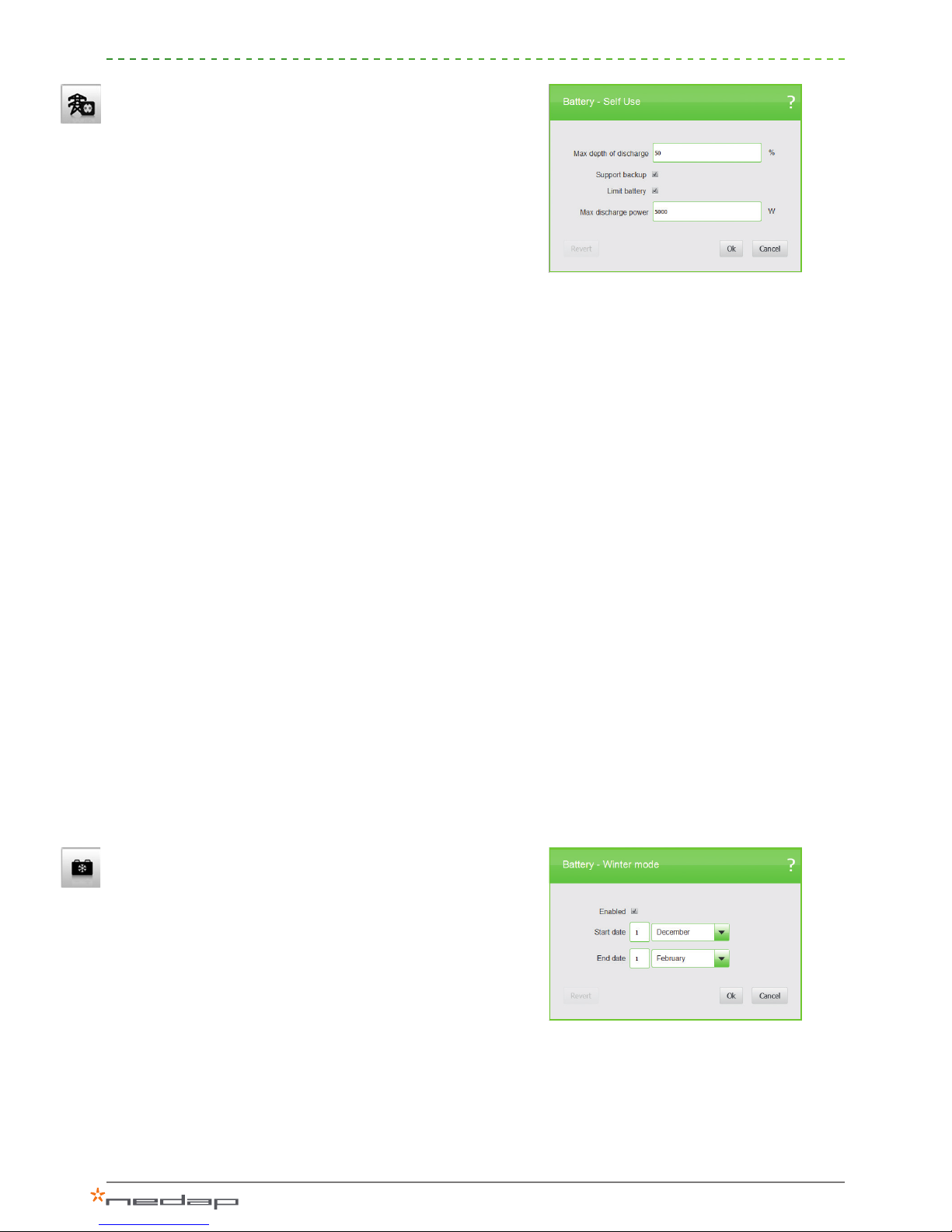
Self-use
With this setting you can set specify battery settings for self-use
optimization.
> Max. depth of discharge. to the default setting is 50%; this
value is preferable for daily use. The battery will not be
discharged beyond 50%. The number of charging cycles that
lead batteries can undergo before reaching the end of their
service life decreases with the depth of discharge. 50% is
recommended as a default value, depending of the exact type
of battery.
> Support backup: if the local out is not used, you can disable
this function. In that case the system will go to standby if the
grid is down and the batteries are fully charged.
>Limit battery to maximum discharge power: With the battery
power limiter enabled, the system will not use the battery to
feed peak loads. This provides extra protection for the battery.
Using a lower battery power for self-use compensation
increases the lifetime of the batteries, because the batteries
are not discharged as quickly. It also improves the self-use
consumption percentage, since at lower discharge powers
more energy can be extracted from the battery.
If the maximum discharge power is set too low, not all the
available battery energy is used. In an ideal situation the
maximum allowed depth of discharge should be reached at the
end of the night.
When batteries are discharged at high power levels, voltage
drops can occur. These can result in under-voltage errors and
potentially damage the battery. Such voltage drops can be
prevented by limiting the discharge power.
Winter mode
With the winter mode enabled, batteries will not be used during
wintertime. This period can be dened by setting a start date
and an end date. During the winter the solar power available is
so limited that your batteries will most likely never become fully
charged or are not used at all. Accordingly, batteries will be run
at lower SOC levels or will remain discharged for weeks between
the maintenance charging cycles. Not using the batteries during
the winter will protect them against damage and will increase
their service life. The maintenance charge mode remains active in
order to keep the batteries fully charged.
Figure 28: Self-use
Figure 29: Winter mode

14
II.
With this setting you can reinstall the PowerRouter system. Please
be aware of the fact that when you reinstall the system you will
lose the basic settings you already have entered. If you want to
cancel the reinstallation, press “Cancel” in the upper-right corner
of this tool.
III.
Check if there are updates available for your system. These
updates include new versions of the system rmware, if available.
> This action requires an Internet connection.
> With this option the rmware will only be loaded into the tool.
w
This option allows you to update the rmware of the connected
system. If a newer rmware version is available for your system,
this will be indicated. You will be asked to conrm, and then the
update will begin. A complete update can take up to 15 minutes
depending on which modules will be updated. During this period
the system will not be operational.
The installation tool already includes the latest rmware versions,
so no internet connection is required to perform a system update.
The following conditions must be met before starting an update:
> The PowerRouter must be properly connected to the grid.
> A battery must be connected to the battery module.
If these conditions are not met, starting an update will result in an
incomplete update. In that case the system becomes unusable
until the entire update is completed.
V.
Change the language of the installation tool.
Once all the settings are completed, the PowerRouter is
ready to function properly and ready for use.
Reinstall
Update rmware
Language
Check for updates
Figure 31: Check for updates
Figure 30: Advanced menu
Figure 32: Update rmware
Advanced
Settings
Reinstall
Check for updates
Update rmware
Language
I.
II.
III.
IV.
V.

15
Supplement: Battery settings for the most common used
battery types
Enersys PowerSafe SBS www.enersys-emea.com
Battery type Number of
batteries
Battery pack
size (C10 Ah)
Maximum
charge current
Bulk voltage Float voltage
SBS 190F 2x 190 Ah 47 A 28,8 V 27,5 V
4x* 380 Ah 95 A
* 2 batteries in series and 2 parallel strings
HOPPECKE OPzV bloc Solar.power www.hoppecke.com
Battery type Number of
batteries
Battery pack
size (C10 Ah)
Maximum
charge current
Bulk voltage Float voltage
6V 4 OPzV 250 4x 205 Ah 41 A 28,8 V 27,0 V
6V 5 OPzV 300 4x 250 Ah 50 A
6V 6 OPzV 370 4x 308 Ah 61 A
BAE Secura PVV BLOCK Solar www.bae-berlin.de
Battery type Number of
batteries
Battery pack
size (C10 Ah)
Maximum
charge current
Bulk voltage Float voltage
6V 4 PVV 280 4x 229 Ah 45 A 28,2 V 27,0 V
6V 5 PVV 350 4x 286 Ah 57 A
6V 6 PVV 420 4x 344 Ah 68 A
www.PowerRouter.com info@PowerRouter.com
Other manuals for PowerRouter
3
Table of contents
Other Nedap Inverter manuals


Popular Inverter manuals by other brands


MAXA
MAXA i-HPV5H 0140 manual

Duracell
Duracell Inverter 3000 installation guide

Mitsubishi Electric
Mitsubishi Electric FR-E540-0.4K-EC instruction manual

Simmonsigns
Simmonsigns Solar LUA installation guide

Ningbo Ginlong Technologies
Ningbo Ginlong Technologies Solis-2.5K-2G Installation and operation manual

Plasmatronics
Plasmatronics D2020N user guide