Nedap Transit Ultimate User manual

TRANSIT ULTIMATE
installation guide
2017-08-17 | v5.01 | 5481104

TRANSIT ULTIMATE | INSTALLATION GUIDE
Content
2/36
CONTENT
1.
INTRODUCTION _______________________________________________________ 3
1.1
PRODUCT DESCRIPTION __________________________________________ 3
1.2
ULTIMATE FEATURES_____________________________________________ 4
2.
INSTALLATION ________________________________________________________ 5
2.1
SAFETY PRECAUTIONS ___________________________________________ 5
2.2
INSTALLATION GUIDELINES _______________________________________ 5
2.3
MOUNTING INSTRUCTIONS _______________________________________ 6
2.3.1
TRANSIT ULTIMATE DIMENSIONS ____________________________ 6
2.3.2
WALL MOUNTING _________________________________________ 7
2.3.3
POLE MOUNTING__________________________________________ 8
2.3.4
WEATHER PROTECTION HOOD ______________________________ 9
2.4
INSTALLING THE SECURITY KEY PACK _____________________________ 10
2.5
INSTALLING A COMMUNICATION BOARD___________________________ 11
3.
CONNECTIONS _______________________________________________________ 12
3.1
OVERVIEW ____________________________________________________ 12
3.2
POWER SUPPLY ________________________________________________ 13
3.2.1
AC MAINS _______________________________________________ 13
3.2.2
DC SUPPLY INPUT ________________________________________ 13
3.2.3
DC OUTPUT _____________________________________________ 14
3.3
COMMUNICATION ______________________________________________ 15
3.3.1
USB ____________________________________________________ 15
3.3.2
WIEGAND / MAGSTRIPE / BARCODE_________________________ 16
3.3.3
RS232 COMMUNICATION _________________________________ 17
3.3.4
RS422 COMMUNICATION _________________________________ 17
3.4
DIGITAL I/O____________________________________________________ 18
3.4.1
RELAY OUTPUT __________________________________________ 18
3.4.2
READ DISABLE INPUT _____________________________________ 19
3.4.3
TAMPER SWITCH _________________________________________ 20
3.4.4
GENERAL PURPOSE INPUTS________________________________ 21
3.5
SPECIAL CONNECTIONS _________________________________________ 22
3.5.1
PROXIMITY ANTENNA _____________________________________ 22
3.5.2
NEDAP ANTENNA MODULATION____________________________ 23
4.
CONFIGURATION _____________________________________________________ 24
4.1
FIRMWARE OPTIONS ____________________________________________ 24
4.2
SERIAL COMMUNICATION SELECT_________________________________ 24
4.3
ULTIMATE-MODE _______________________________________________ 25
4.4
RANGE BEEPER_________________________________________________ 25
4.5
FREQUENCY SELECTION _________________________________________ 26
4.5.1
FREQUENCY SELECT DISPLAY & BUTTONS ___________________ 26
4.5.2
FREQUENCY SELECT DIP-SWITCHES_________________________ 26
4.6
READ RANGE CONTROL _________________________________________ 27
4.7
MICROWAVE TIME-SHARING _____________________________________ 28
5.
LED INDICATIONS ____________________________________________________ 29
5.1
MAIN BOARD INDICATIONS ______________________________________ 29
5.2
TAB BOARD INDICATIONS________________________________________ 30
A
TECHNICAL SPECIFICATIONS ___________________________________________ 31
B
FREQUENCY CHANNELS _______________________________________________ 32
C
NEDAP PART NUMBERS________________________________________________ 33
D
FCC / IC STATEMENT __________________________________________________ 34
E
DISCLAIMER _________________________________________________________ 35
F
DOCUMENT REVISION_________________________________________________ 36

TRANSIT ULTIMATE | INSTALLATION GUIDE
INTRODUCTION
3/36
1. INTRODUCTION
1.1
PRODUCT DESCRIPTION
The TRANSIT Ultimate is a long-range reader, based on semi active RFID technology,
which enables automatic vehicle identification at distances of up to 10 meters (33
ft.) and speeds of up to 200 km/h (125 mph).
Key features
Robust industrial design
Read range up to 10 meters [33 ft.]
Object speed up to 200 km/h [125 mph]
Adjustable read range
Selectable frequency channels
Variety of integrated communication interfaces
3 color LED indication
Tag authentication based on AES encryption
Bi-directional tag communication
Backwards-compatible with previous TRANSIT readers.
Frequency channels
The TRANSIT Ultimate operates on a factory-set frequency channel. Different
frequency channels allow multiple readers to operate in close vicinity of each other
without interference.
Read range adjustment
The reader efficiently resolves typical multi-lane, entry and exit reader challenges.
The read range of the TRANSIT Ultimate can be adjusted to offer secure and reliable
identification in demanding applications.
Housing & mounting
The TRANSIT Ultimate is intended for outdoor installation.
The weatherproof TRANSIT Ultimate reader features an IP66 certified housing. The
reader operates reliable under harsh environmental conditions and is able to
withstand exposure to rain, snow and ice. Wall mounting equipment is included.
Interfaces & protocols
The TRANSIT Ultimate is designed for seamless and flexible integration into existing
management systems in the industry, such as security, parking, and logistics. Several
communication interfaces to the host system are available such as RS232, RS422,
RS485, Profibus-DP and TCP/IP. Also open industry-standards protocols such as
Wiegand, Magstripe and Barcode are supported. Customer specific protocols can be
implemented on request.

TRANSIT ULTIMATE | INSTALLATION GUIDE
INTRODUCTION
4/36
1.2
ULTIMATE FEATURES
Encrypted tag authentication
The TRANSIT Ultimate enables encrypted tag authentication for the Ultimate tags:
Smartcard Booster Ultimate, LEGIC Booster Ultimate and Window Tag Ultimate. The
authentication uses encryption based upon AES 128-bit keys. Key diversification is
used to ensure that a unique encryption key is used for every tag.
Data storage
Thanks to the bi-directional tag communication feature and in combination with
Smartcard-Booster Ultimate it will be possible to write information on the drivers’
access control card when the car enters or leaves a perimeter. This will enable write
actions like changing credits, offline access rights or other information changes
dynamically upon perimeter access.
Implementation
The Ultimate-mode features are implemented in the TAB board. The TAB-board
performs the authentication or other Ultimate function using the bi-directional tag
communication channel at 433MHz.
Figure 1: TRANSIT Ultimate block diagram
Authentication procedure
The encrypted tag authentication is performed when both antennas (433MHz and
2.45GHz) receive the same id-number. This ensures that the tag to be authenticated
is located in the well-defined directional beam in front of the reader.
1. Receive Ultimate tag id-number.
2. Send encrypted challenge to the tag.
The challenge is generated by the Security Key Pack based upon random
numbers encrypted with a diversified AES128 key.
3. Receive, decrypt and verify the encrypted challenge response from the tag.
4. When the authentication is successful, the id-number is transmitted on the
communication output(s). Wiegand, USB, etc.
TRANSIT - PIC
2.45GHz 433MHz
Ultimate
mode
bypass
Serial com-select
USB-detect
USB
I/F-board
Wiegand
Relay output
Smiley RGB
TAB-board
Security Key Pack
TRANSIT Ultimate
Note
The TAB board may be
bypassed to make the
TRANSIT Ultimate fully
compatible with the
TRANSIT Standard. See
chapter 4.3.

TRANSIT ULTIMATE | INSTALLATION GUIDE
INSTALLATION
5/36
2. INSTALLATION
2.1
SAFETY PRECAUTIONS
The following safety precautions should be observed during normal use, service and
repair:
The TRANSIT Ultimate shall be connected to safety ground.
Disconnecting from (mains) power supply before removing any parts.
The TRANSIT Ultimate shall only be installed and serviced by qualified service
personnel.
To be sure of safety, do not modify or add anything other than mentioned in this
manual or indicated by NEDAP N.V.
2.2
INSTALLATION GUIDELINES
The TRANSIT Ultimate can be installed in any position. The normally expected read
range is up to 10 meters.
Usually the reader is mounted in the horizontal position. In this case the coverage
area in the horizontal plane is maximized. The horizontal beam is 80 degrees.
Horizontal mounting: 80 degrees wide read coverage.
In some applications a vertical installation is required to make use of the smaller
beam width in the vertical plane. The vertical beam is 40 degrees. This can be very
useful in applications with multiple driving lanes to prevent cross readings.
Vertical mounting: 40 degrees narrow read coverage.
The Wall Mounting Set, which make rotation in the vertical and horizontal plane
possible, is standard included with every TRANSIT Ultimate.

TRANSIT ULTIMATE | INSTALLATION GUIDE
INSTALLATION
6/36
2.3
MOUNTING INSTRUCTIONS
See the following chapters for details about the dimensions of the reader and the
mounting brackets and the locations of the mounting positions.
2.3.1
TRANSIT ULTIMATE DIMENSIONS
The picture below shows the dimensions of the TRANSIT Ultimate.
All dimensions are in mm.
Figure 2: Dimensions TRANSIT Ultimate
326 mm 109 mm 31
271 mm
60 mm
274 mm
TRANSIT ULTIMATE | INSTALLATION GUIDE
INSTALLATION
7/36
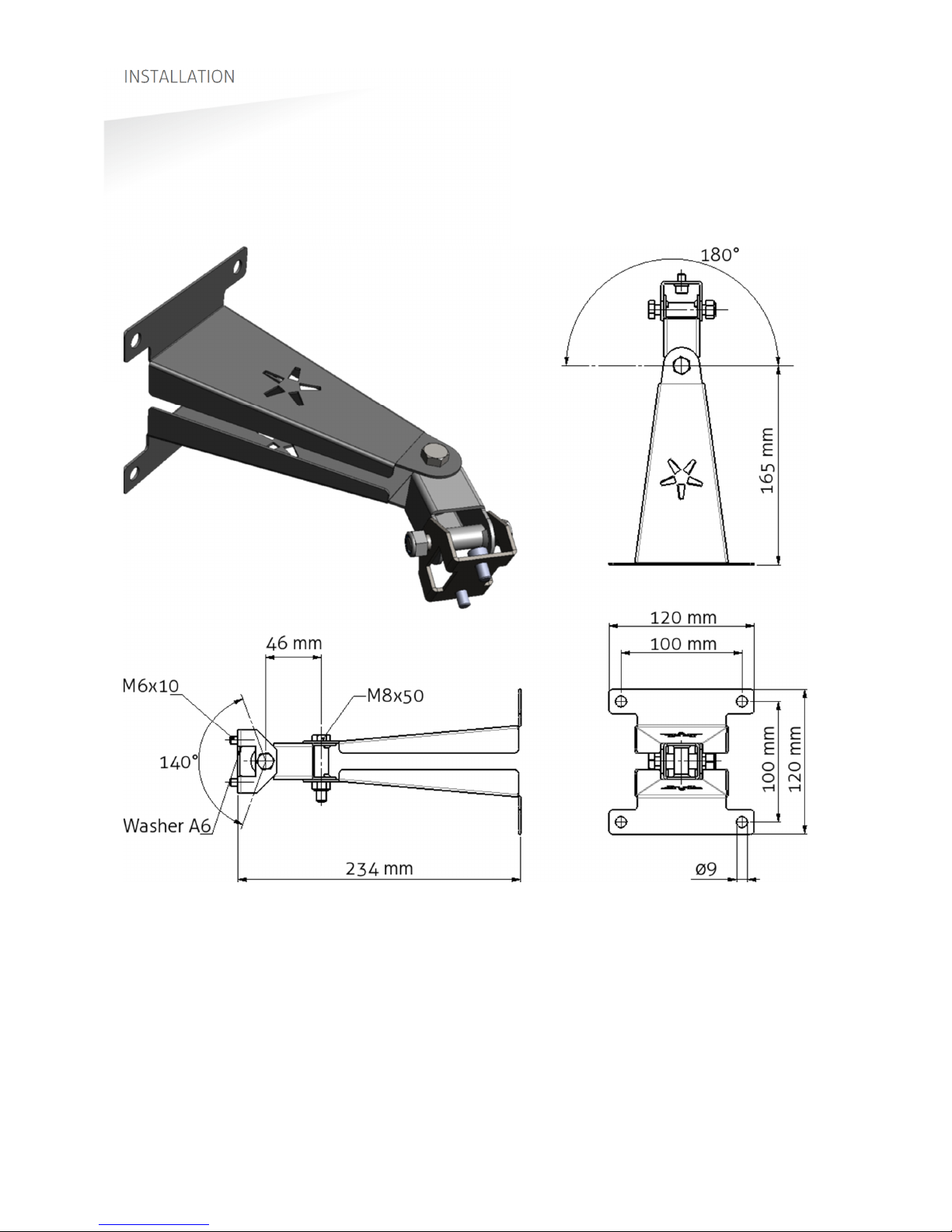
2.3.2
WALL MOUNTING
The Wall Mounting Set is supplied with the TRANSIT Ultimate reader. When the Wall
Mounting Set is assembled mount it to the wall (or to the Pole Mounting Set) based
on the dimensions in Figure 3. The TRANSIT Ultimate can be “aimed” with the Wall
Mounting Set and when the bolts are tightened, it will stay in place.
Figure 3: Wall Mounting Set

TRANSIT ULTIMATE | INSTALLATION GUIDE
INSTALLATION
8/36
2.3.3
POLE MOUNTING
The Pole Mounting Kit has to be ordered separately (art. no. 5626595).
The TRANSIT Ultimate can be mounted to round poles with maximum diameter of
190 mm and square poles with maximum diameter of 150 mm using the Pole
Mounting Kit.
Note that the Wall Mounting Set will be mounted onto the Pole Mounting Kit.
Figure 4: Dimensions Pole Mounting Kit
140 mm
172 mm
43 mm
100 mm
100 mm

TRANSIT ULTIMATE | INSTALLATION GUIDE
INSTALLATION
9/36
2.3.4
WEATHER PROTECTION HOOD
The Weather Protection Hood has to be ordered separately (art. no. 9218327).
It is recommended when the reader is installed in places where direct sunlight may
overheat the reader.
Figure 5: Dimensions Weather Protection Hood
354 mm 27 mm 75 mm
287 mm
TRANSIT ULTIMATE | INSTALLATION GUIDE
INSTALLATION
10/36
2.4
INSTALLING THE SECURITY KEY PACK
The optional Security Key Pack (SAM) has to be ordered separately (art. no. 9216537)
and is required for the TRANSIT Ultimate to perform the encrypted authentication on
the Ultimate tags. Please follow the procedure below to install the Security Key Pack
into the TRANSIT Ultimate.
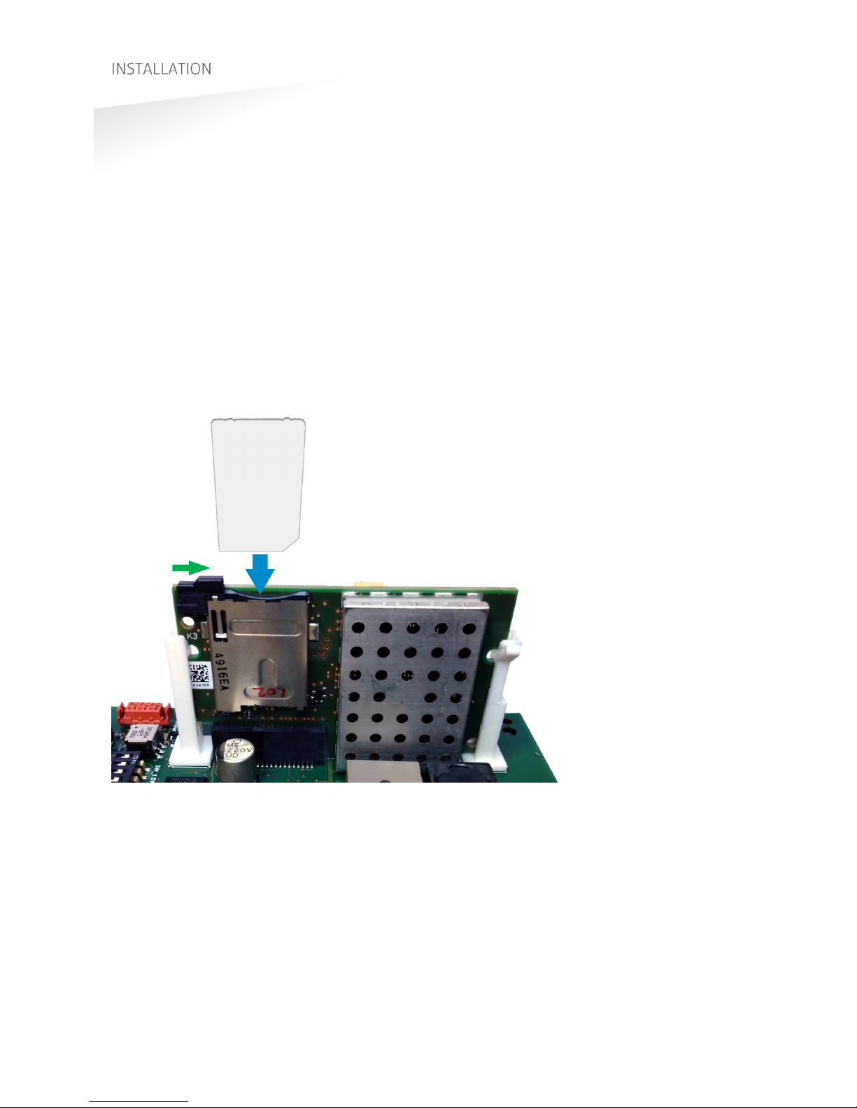
Security Key Pack installation procedure
Insert the Security Key Pack (SAM) into the TAB board.
1. Align the notch as indicated in Figure 6 and keep the metal contacts backwards.
2. Push the SAM into the slot until it clicks into place.
3. Set the LOCK-switch to the right to lock the SAM.
4. Enable the Ultimate-mode by settings dip-switch SW2-2 ON. See chapter 4.3.
Removal procedure
1. Set the LOCK-switch to the left to release the SAM.
2. Push the SAM to eject it.
3. Disable the Ultimate-mode by setting dip-switch SW2-2 OFF. See chapter 4.3.
Figure 6: Installing the Security Key Pack (SAM)
SAM
LOCK

TRANSIT ULTIMATE | INSTALLATION GUIDE
INSTALLATION
11/36
2.5
INSTALLING A COMMUNICATION BOARD
The TRANSIT Ultimate features an on-board USB port and a Wiegand / Magstripe /
Barcode interface. See chapter 3.3 for more details.
Other communication interfaces can modularly be installed in the reader by means
of a communication interface board. There are various communication interface
boards available for the TRANSIT Ultimate. See appendix C for available boards and
their part numbers.
Make sure to follow all safety precautions outlined in chapter 2.1 when installing or
replacing a communication board.
Communication board installation procedure:
1. Open the TRANSIT Ultimate. You can put the cover strut into place to keep the
cover open.
2. Disconnect the power supply.
3. Place the communication interface board on the 14-pin header K5 as indicated
in the picture below.
4. Make sure that the 4 plastic PCB supports are properly positioned and fixed into
the communication board.
5. Read the communication board’s installation guide for additional notes like
address setting, jumper settings and wiring details.
6. Test if the communication works correctly.
7. Close the cover of the TRANSIT Ultimate.
TRANSIT ULTIMATE | INSTALLATION GUIDE
CONNECTIONS
12/36
3. CONNECTIONS
3.1
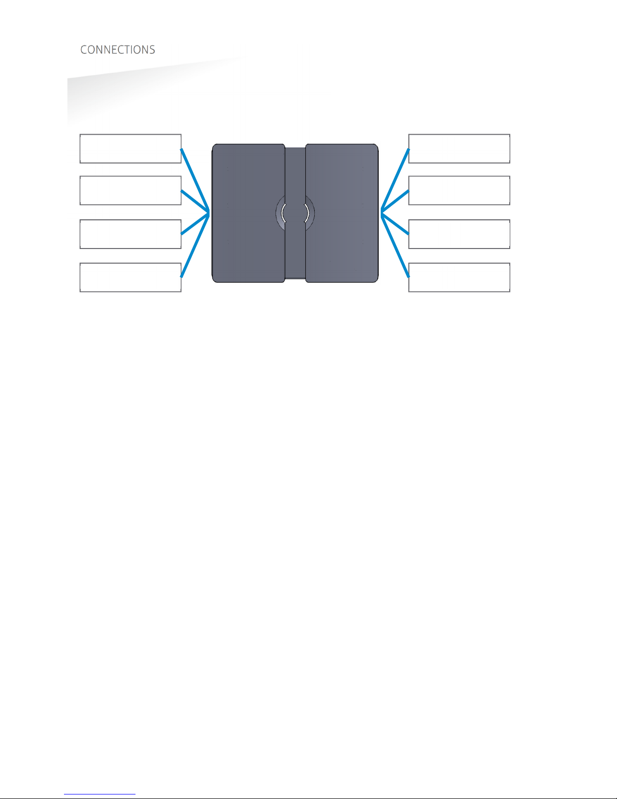
OVERVIEW
Figure 7: TRANSIT Ultimate connections overview
Power supply
See chapter 3.2
Read-disable input
See chapter 3.4.2
General purpose inputs
See chapter 3.4.4
Proximity antenna
See chapter 3.5.1
Relay output
See chapter 3.4.1
Tamper switch
See chapter 3.4.3
Communication
See chapter 3.3
Antenna modulation
See chapter 3.5.2
TRANSIT ULTIMATE | INSTALLATION GUIDE
CONNECTIONS
13/36
3.2
POWER SUPPLY
The TRANSIT Ultimate can be powered by AC mains or by a 24 VDC power supply.
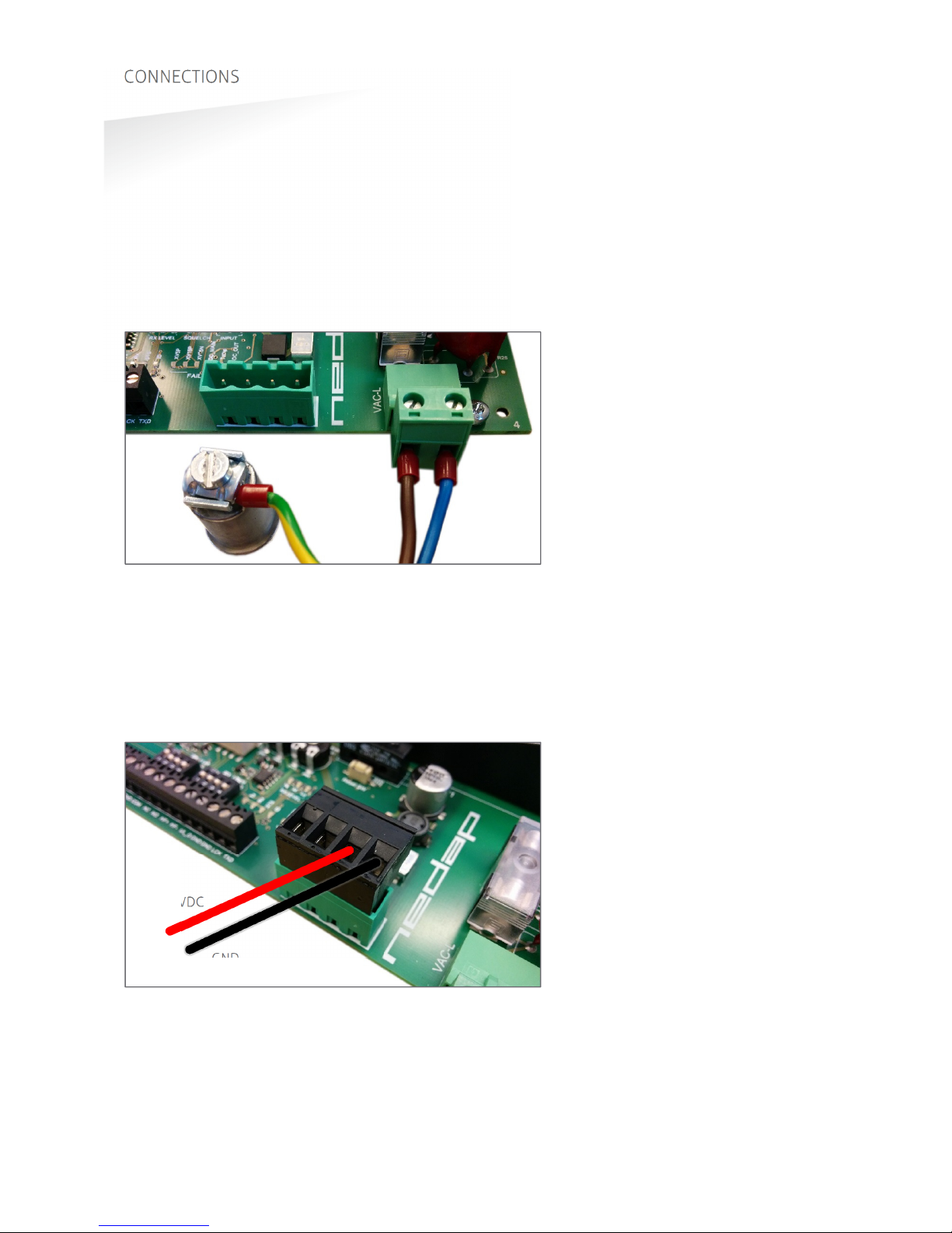
3.2.1
AC MAINS
Connect the Mains load and neutral wires to the connector terminals VAC-L and
VAC-N. The earth wire should be connected to the dedicated safety ground
connection.
Input voltage: 100 – 240 VAC
Frequency: 60 – 50 Hz.
Figure 8: AC mains connections
3.2.2
DC SUPPLY INPUT
Connect the DC power supply to the connector terminals as indicated below.
Remove the connector for easy fixing the wires.
Input voltage: 24 VDC ± 10%
Max. input current: 700 mA @ 24 VDC
Figure 9: DC input connections
GND
+24VDC
VAC-L VAC-N
GROUND

TRANSIT ULTIMATE | INSTALLATION GUIDE
CONNECTIONS
14/36
3.2.3
DC OUTPUT
The DC output can be used to supply power to an additional device installed inside
or near the TRANSIT Ultimate.
Figure 10: DC output connections
DC output ratings
Output voltage: 23.4 VDC ± 10%
Max. output current: 100 mA.
GND
+DC-OUT
TRANSIT ULTIMATE | INSTALLATION GUIDE
CONNECTIONS
15/36
3.3
COMMUNICATION
3.3.1
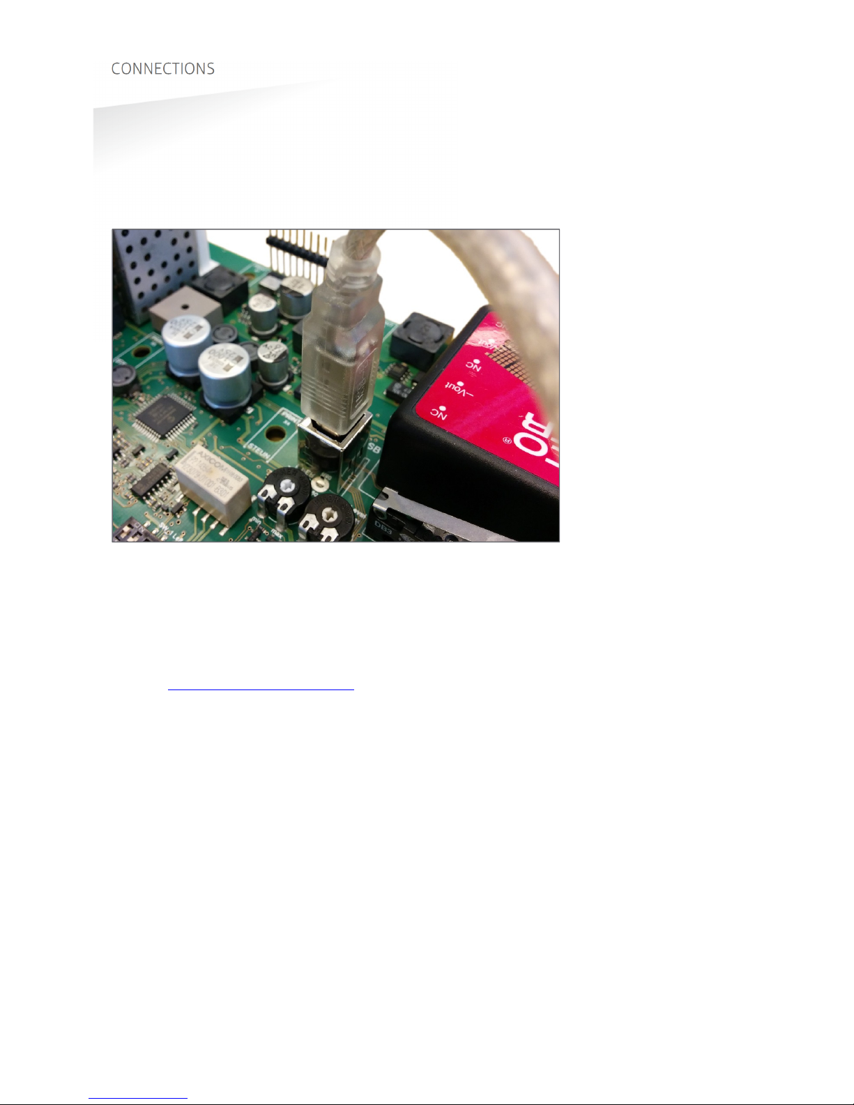
USB
The TRANSIT Ultimate features an USB interface for service and installation
purposes. The USB connector (Type B) is accessible behind the cover. While the USB
interface is in use, the optional communication interface board is disabled.
Figure 11: USB connection
USB Virtual Com Port driver installation
Make sure your computer is connected to the internet. The driver usually is installed
automatically via Windows update when the USB interface is connected to your PC.
Follow the driver installation wizard. If you do not see the Windows update pop-up,
you can manually install the driver. To manually install, you need to go to FTDI’s
website at www.ftdichip.com/Drivers/VCP.htm and download the VCP (Virtual Com
Port) drivers for your operating system. Drivers for MacOS and Linux are available as
well.
TRANSIT ULTIMATE | INSTALLATION GUIDE
CONNECTIONS
16/36
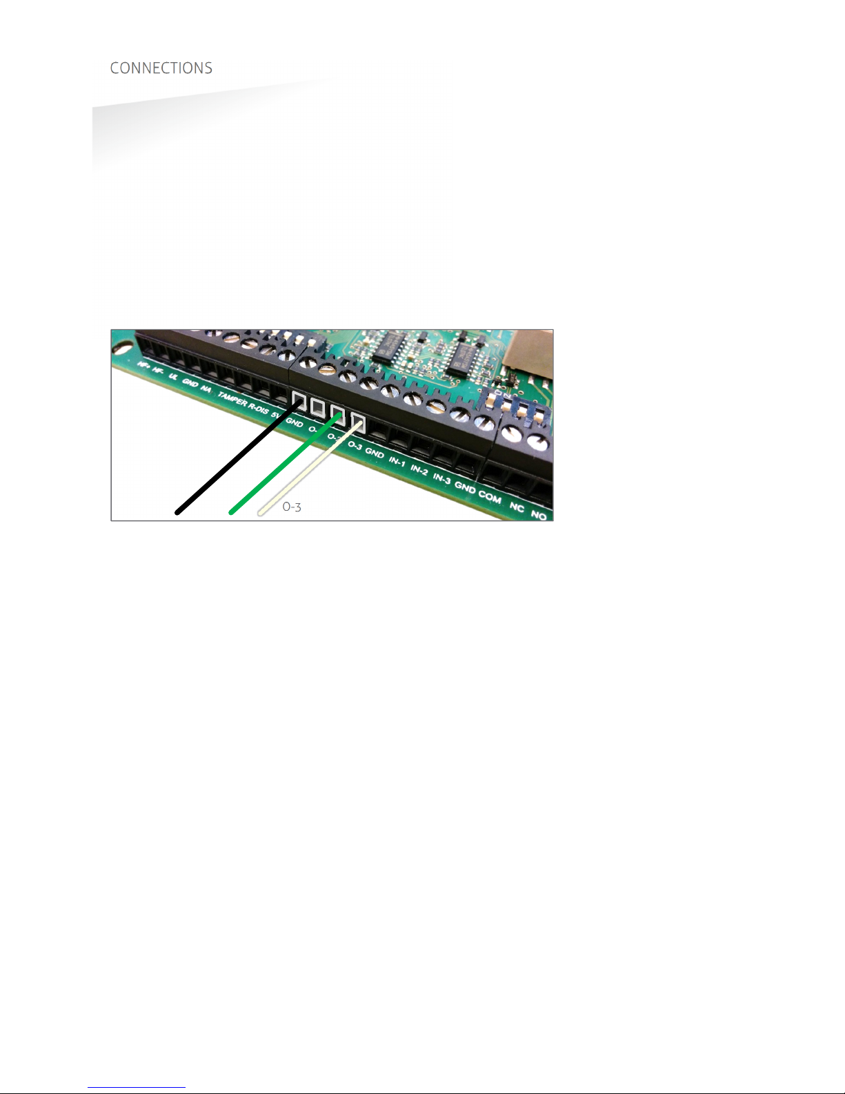
3.3.2
WIEGAND / MAGSTRIPE / BARCODE
The synchronous communication interface wiring uses the connections described
below. The actual protocol output depends upon the reader firmware. Please refer to
the firmware manual for more details.
Connections Wiegand Magstripe Barcode
O-1
- Card Loaded -
O-2
Data-0 (green) Clock -
O-3
Data-1 (white) Data Data
GND
Ground (black) Ground Ground
The picture below illustrates the Wiegand wiring.
Figure 12: Wiegand wiring
Cable specification:
4 x 0.25mm
2
shielded
Maximum cable length: 150 meter.
GND O-2 O-3

TRANSIT ULTIMATE | INSTALLATION GUIDE
CONNECTIONS
17/36
3.3.3
RS232 COMMUNICATION
TRANSIT SIDE
DIN 25 Name
PC SIDE
DIN 9 Name
2 TXD
2 RXD
3 RXD 3 TXD
7 GND
5 GND
Cable specification:
3 x 0.25mm
2
shielded
Maximum cable length: 30 meter.
3.3.4
RS422 COMMUNICATION
RS422 RS485
Jumper in position RS422. Jumper in position RS485.
CM422/485 RS422 HOST
TX+RX+
TX-RX-
RX+TX+
RX-TX-
Cable specification:
2 x 2 x 0.25mm
2
twisted pair shielded
Maximum cable length: 30 meter.
CM422/485 RS485 HOST
TX+-
TX--
RX+A (-)
RX-B (+)
TRANSIT ULTIMATE | INSTALLATION GUIDE
CONNECTIONS
18/36
3.4
DIGITAL I/O
3.4.1
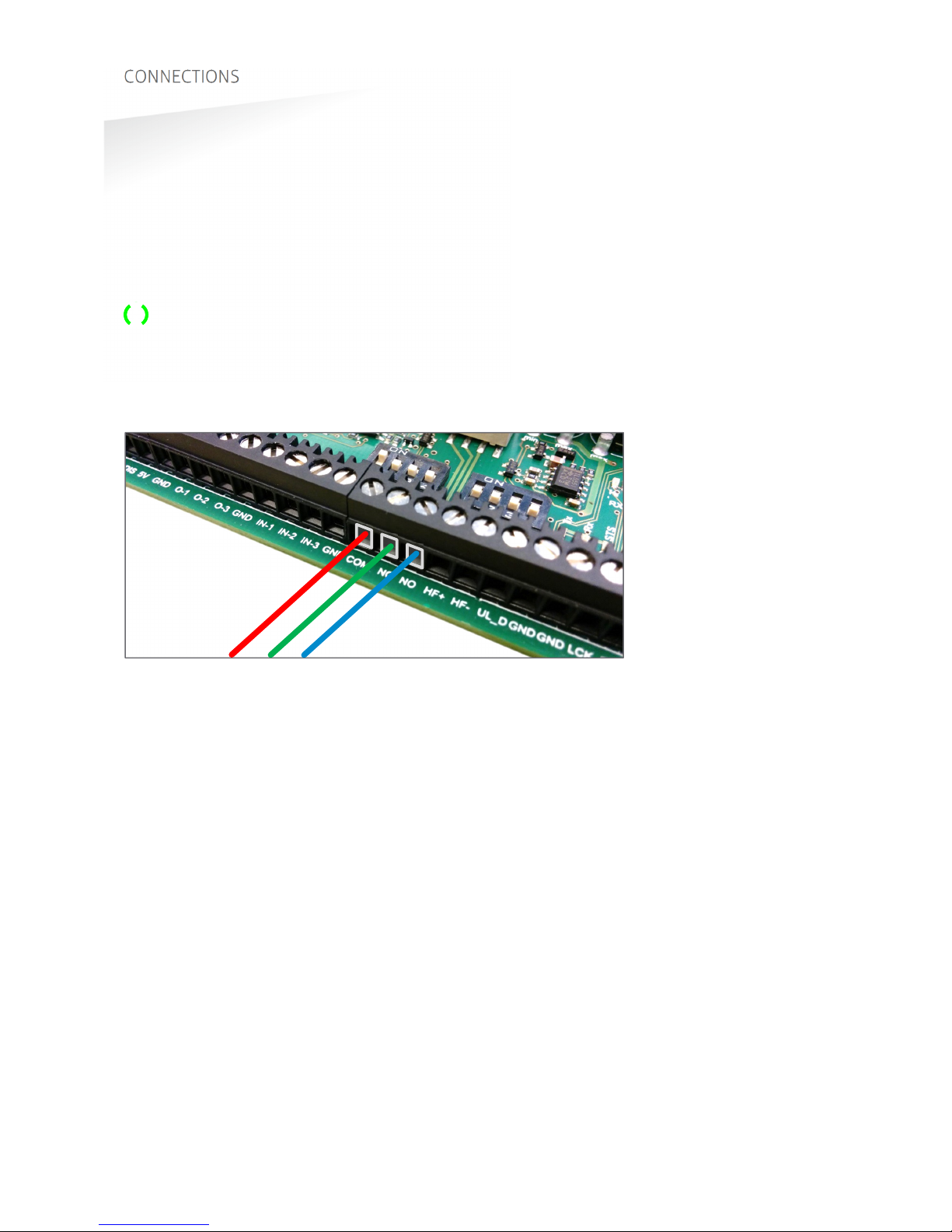
RELAY OUTPUT
The relay output is automatically activated upon successful identification /
authentication of a transponder. The automatic-relay-activation-mode can be
configured using the firmware. Please refer to the firmware manual for more details.
Authentication is only performed when Ultimate-mode is enabled. See chapter 4.3
for more details.
The front cover LED lights-up simultaneously with the relay output.
Connections:
NO
Relay contact normally open
NC
Relay contact normally closed
COM
Relay contact common
Figure 13: Relay output connections
Contact ratings:
Max. switching current: 2A
Max. switching voltage: 24VDC
Max. switching power: 50W
COM NC NO
TRANSIT ULTIMATE | INSTALLATION GUIDE
CONNECTIONS
19/36
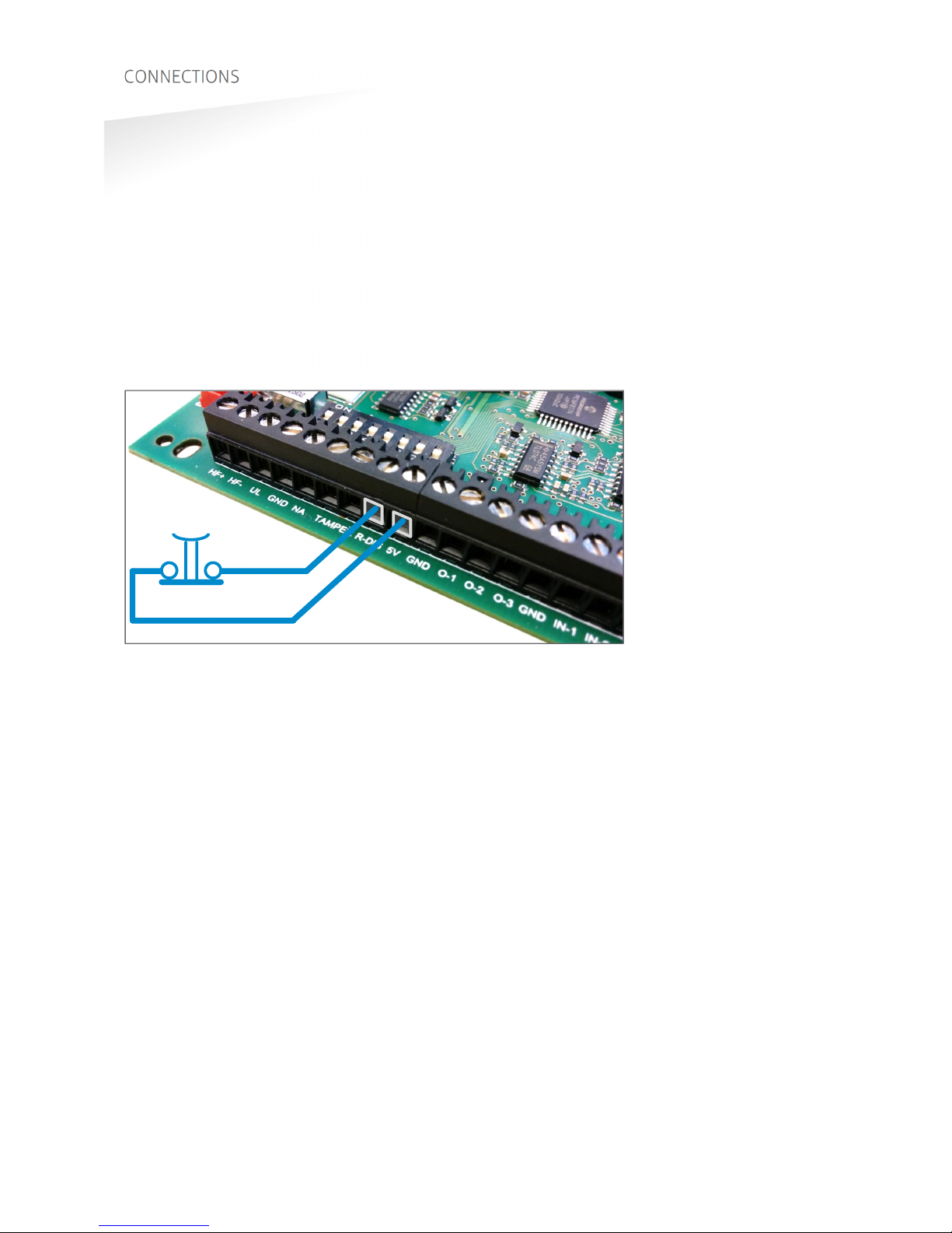
3.4.2
READ DISABLE INPUT
The reading of the TRANSIT Ultimate can be completely disabled with the read
disable input (RDIS). This input is commonly used in combination with a sensor (e.g.
inductive loop) that detects the presence of a person or vehicle. Use always a relay
contact to connect the internal 5V to the RDIS input. When the RDIS input is unused,
reading is enabled.
Connections:
R-DIS
Read disable input
5V
Internal 5V source for read disable input.
Warning: using an external 5V supply could damage the reader.
Figure 14: Read disable input
R-DIS
5V

TRANSIT ULTIMATE | INSTALLATION GUIDE
CONNECTIONS
20/36
3.4.3
TAMPER SWITCH
The TRANSIT Ultimate features an internal tamper switch that indicates when the
cover is opened. This contact may be connected to an external alarm system. The
contacts are normally closed when the cover is in place.
Tamper switches of multiple TRANSIT Ultimate readers may be connected in series.
Connections:
TAMPER
Tamper switch contacts (normally closed)
TAMPER
“
Contact ratings:
Max. switching current: 50 mA (0.5V voltage drop)
Max. switching voltage: 24 VDC
Figure 15: Tamper switch
TAMPER
Other manuals for Transit Ultimate
1
Table of contents
Other Nedap Other manuals


Popular Other manuals by other brands


Lascar
Lascar EL-CC-2-001 quick start guide

American Bath Factory
American Bath Factory Sistine Stone Neo Angle installation guide

LAMBORGHINI
LAMBORGHINI INOVA 20 CS W - SCHEMA manual

TYAN
TYAN ADDENDUM Notice

ACA Digital Corporation
ACA Digital Corporation RF1100 user manual

SANPLAST
SANPLAST TX4 Series installation guide


