Neilsen CT3324 User manual

1
Specification of Multifunction Machine
MF360

2
B65 0JU.U.K.

3
Preface
Please read the specification carefully before using the machine; and proceed to operate it rigidly based on
the manual in case any incidents occurred to people, machines and tools.
Main technical parameters:
Parameters Names Parameters values
Gasoline engine type Air cooled vertical single-cylinder four-stroke engine
Rated power/speed (HP/rpm)6.5/3600
Displacement(CC)196
Noise(dB)96
Capacity of fuel tank(L)3.6
Capacity of sump(L)0.6
Output rotated speed (RPM)920/675
Transmission 2 forward / 2 reverse
Wheel span(cm)40
Starting method recoil
Net weight(Kg)63
12
3
5
6
7
8
9
1
0
11
12
1
3
1
5
1
6
17
1
8
1
9
14
4
Product Picture
Diagram 1

4
Four accessories and an operating manual are included in the packing case.
Customers are advised to check out to see whether all the accessories are included in the
packing case before assembling them.
10.handrail
11. worm gear clutch handlebar
12. height adjustment handlebar
13.speedcontroller
14. gears joystick
15. emergency cut-off handle
16. input clutch handle
17. output clutch handle
18. start handle
19. transmission case
1. fueltank
2. airfilter
3. muffler
4. protective bracket of engine
5. rubber tire
6. accessories’ connector bush
7. locating pin handlebar
8. axis pin use for change the girder's direction
9. girder
1
4 2 3

5
Warning signs
Children and grownups who have not read instructions are’t allowed to operate the machine.
Make sure there is nobody in working area, especially children and pets.
Keep away from heat source and combustibles.
Description of Product Installation:
1. Disassembly the two screws on the gearbox. See the diagram 2 below.
2. Assemble the wheel casing and tighten the screws up. See the diagram 3
3. Disassemble the bolts M10×25 at the side of the turbine shaft and take out of the adjustable pad. See the
diagram 4
4. Assemble rubber tire to turbine shaft and make sure the axle pin is stuck in the slot. See the diagram 5.
5. If the diameter of spoke end face is 1mm greater than the worm wheel end face’s, it is needed to add a
adjustable pad. If not, it is not needed. See the diagram 6.
6. Finally tighten the bolts up. See the diagram 7.
Please read instructions carefully
before using it and operate the
machinery safely when in
operation.
Unplug sparkplug cap when
repairing and maintaining the
machine.
Diagram 4
BoltM10×25
Adjustable padφ35×φ25×1
Diagram 5
Axle pin
Axle pin slot
Diagram 2
ScrewM6×20
Diagram 3
Wheel casing
People must keep a safe distance from
the machine.
Don’t touch rotary section of
the rotary tillage knives or
otherwise it may cause injury.
It is necessary to wear safety
goggles and ear protection when
operating the machine.

6
7. Disassemble the four nuts M8. See the diagram 8.
8. Assemble the joint linking sleeve and fasten the nuts。See the diagram 9.
9. Disassemble the two nutsM8. See the diagram 10.
10. Give two lock pressure plates of handrail a 180-degree change. See the diagram 11.
11. The first thing is to push down the height control hand lever and then assemble the handrail, with stop pin
stuck in the slot of handrail. (It is better to put the stop pin in the middle of slot.) See the diagram 12.
12. Pull lock pressure plates a 180 to bear on handrail and screw nuts. See the diagram 13.
13. When screw the four nuts of the lock pressure plate of handrail, take care of two following points:
●When fastening the four nuts, the distance which nuts are screwed into is required the same.
●When fastening the four nuts, It is required to push down the height control hand lever, and the handrail
can turn but not shake.
Diagram 7
Diagram 6
Worm wheel end faceSpoke end face
Diagram 8
NutM8
Diagram 9
Accessories’connector bush
Diagram 10
Nut M8
Diagram 11
Lock pressure plate of handrail

7
14. Disassemble the two cotter pins and two plastic bags from the gear lever. See the diagram 14.
15. Put two plastic covers on the two gear levers relatively, and then plug the levers in the hole of plastic covers
with cotter pin. See the diagram 15.
Operation and Use
A、The Function and Usage of Main Assemblies
It is necessary to know the function and usage of main assemblies to operate the machine more safely.
1. Steering hand lever
●Different assembly needs different handrail.
●Rotary direction of handrail is required. Please refer to the instruction. See the diagram 19.
Diagram 12
Height control hand lever
Stop pin
Hand rail
Diagram 13
Diagram 14
Gear lever
Cotter pin
Diagram 15
Current state of handrail
Rotary direction of handrail
Diagram 19
Gear identification
Plastic bag

8
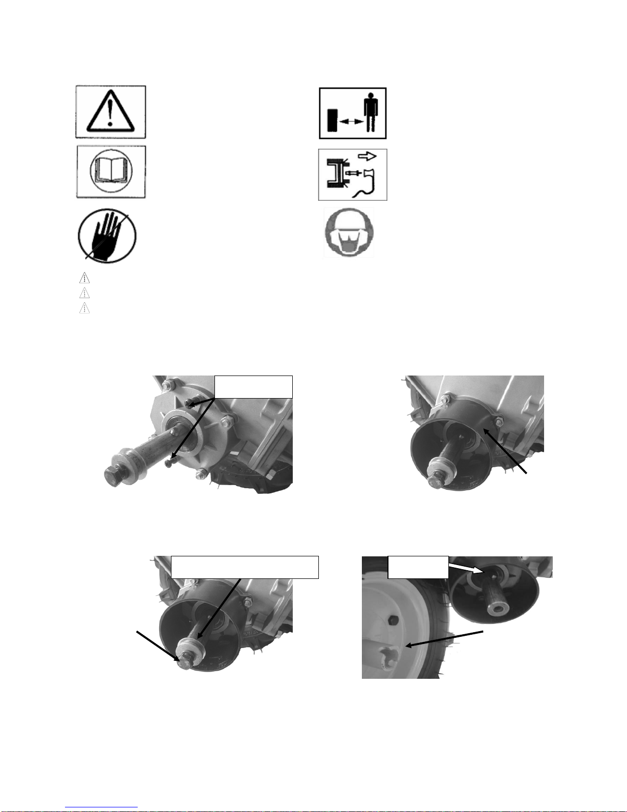
●Pull the cotter pin and the gear lever. See the diagram 20.
●Pull the steering hand lever and rotate it in accordance with instruction to suitable position and then
disengage it. See the diagram 21.
●Finally assemble the gear lever and cotter pin and arrange all the assemblies.
2. Height Control Hand Lever
●Customers could adjust the height to a suitable position by pushing down the height control hand lever. See
the diagram 22.
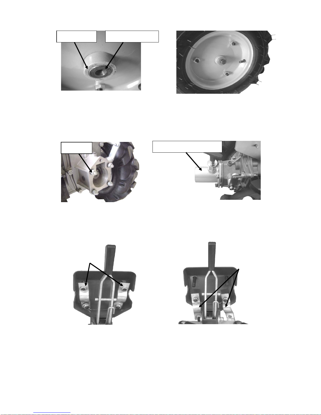
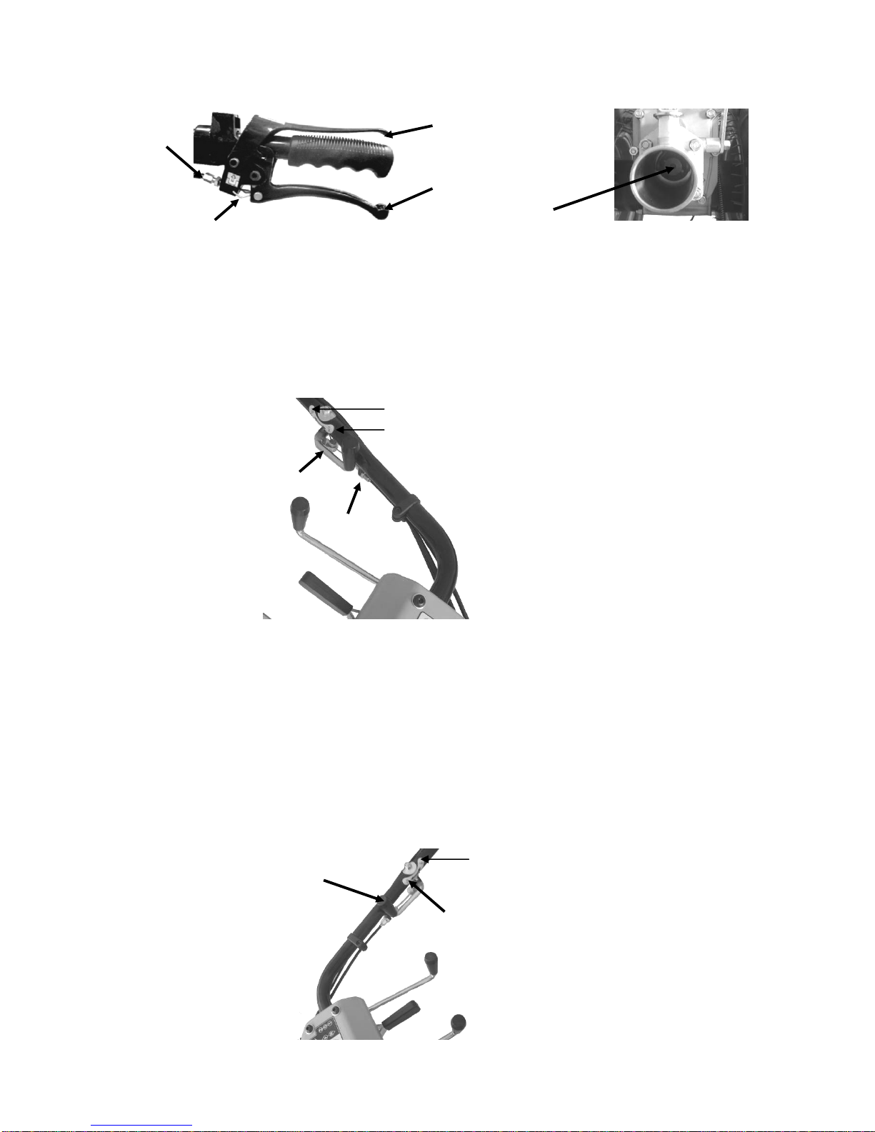
3. Input clutch handlebar and emergence shut-down handlebar
●Input clutch handlebar is meant to control the travel of gearbox. Under normal circumstance, it must be
disengaged. While when the engine starts or shifts the gear, it is necessary to hold the handlebar to protect the
gears from damage. See the diagram 23.
●Emergence shut-down handlebar is used to control gasoline flameout. Under working condition, the
handlebar must be held. If you don’t, the engine will stop. See the diagram 23.
●It is very important to learn to use input clutch handlebar and emergence shut-down handlebar. You must first
pull the latter and then the former. When disengaging the handlebar, we must bear against the input clutch
handlebar with guard ring. See the diagram 23.
●If you want to disengage the input clutch handlebar, open the guard ring and then the it will be disengaged
automatically.
●The Debugging of Input Clutch: Debug it without starting up. Release the handle of input clutch and lightly
tug the gasoline engine, then the output shaft should be rotating. If not, please turn the adjusting bolt
towards inner side. Seize the handle of input clutch; prop it with the guard ring and lightly tug the gasoline
engine, then the output shaft should not be rotating. If not, please turn the adjusting bolt towards the
outward side. See the diagram 23 and 24.
Diagram 20
Cotter lever
Gear lever
Steering hand lever
Diagram 21
Height control hand lever
Diagram 22

9
4. Handle of Output Clutch
●The handle of output clutch mainly controls the work of attachment.
●The attachment start to work when the handle is in the position of ON while it stops working when the
handle is in the position of OFF. See the diagram 25.
●The output clutch cannot be debugged unless it is connected to attachment. Please see the direction on
Page 9.
5. Handle of Worm Wheel Clutch
●The handle of worm wheel clutch mainly control the running of rubber tires. See the diagram 26.
●When the handle is in the position of ON, the rubber tires can run; While the handle is in the position of OFF,
the tires cannot run, but can be propelled. See the diagram 26.
●The Debugging of Worm Wheel Clutch: Debug it without starting up. When the handle is in the position of
ON, rubber tires cannot be propelled. If not, please turn the adjusting bolt towards inner side. When the
handle is in the position of OFF, rubber tires can be propelled. If not, please turn the adjusting bolt towards
the outward side. See the diagram 26.
Handle of output shaft
Diagram 25
OFF
ON
OFF
Handle of worm wheel
Diagram 26
Adjusting bolt
Adjusting bolt
Diagram 23
Input clutch handle
Handle for emergency
shutdown
Guard ring
Adjusting bolt
Output shaft
Diagram 24

10
6. Gear Control Lever
●There are two gear control levers on this machine, of which one is to control the gear of forward and
reverse and the other is to control the gear of rapid and low. See the diagram 27.
●Explanation of Gear Marks: See the diagram 19.
1- Low Gear 2- Rapid Gear 0- Neutral Gear F- Forward Gear R- Reverse Gear
●When connecting different attachments, maybe the handrail needs to be steered. Therefore there may be
differences. Please carefully read the explanation of marks. See the diagram 19.
●Attention: The handle of clutch must be seized when varying gears during the working process! See the
diagram 23.
7. Governor
●Governor mainly control the rotating speed of gasoline engine. See the diagram 28.
B、The Correct Way to Connect Attachments
1. Before connecting attachments, it should be the first to check that whether the ridge orientation is according
to the one of rotation. See the diagram 29.
Attention: If not, the creep force of rubber tires will be affected!
Gear control levers
Diagram 27
High speed
Low speed
Diagram 28
Governor
Diagram 29

11
2. Turn the handle of output clutch to the position ON. See the diagram 25.
3. For the easy installation of the accessories, please elevate the rear part of gasoline engine for about 20cm
to keep the machine almost in the horizontal position. See the diagram 30.
4. Pull up the hand shank of the dowel pin and stick the connecting parts of the accessories into the hole of the
accessories’ connector bush. When the connecting parts stick into the bottom, pull down the hank shank of the
dowel again. Revolve the accessory slightly and make sure that the dowel pin can stick into the dowel hole of
the accessories’ connecting parts. See the diagram 31
5. Debug of the output clutch: When the hand shank is in position “ON”, pull the petrol engine slightly then the
working parts of the accessories can revolve. If the working parts of the accessories cannot revolve, please
debug the bolt inside. When the hand shank is in position “OFF”, the working parts of the accessories cannot
revolve. If they can revolve, please debug the bolt outside. See the diagram 25
C、Startup Operation
1. Infuse the petrol engine with lubrication oil
●Choose proper brand of the lubrication oil according to the temperature differences in working condition. Use
SAE 10W-30 and SAE 30 generally. See right-hand chart
●The normal lubrication oil quantity for the petrol engine is ranging form 0.6L to 0.9L.
●.When the petrol engine is in horizontal position, refuel the oil to the lower edge of the oil hole. See the
diagram 32
●Attention: Any use of dirty or other brands of the lubrication oil will impact the petrol engine’s working life!
Below the normal state when refueling will also damage the petrol engine badly!
Diagram 30
Diagram 31
Accessories’
connector bush
Hand shank of the
dowel pin
Diagram 32

12
2. Infuse the fuel oil into the fuel tank of the petrol engine
●Choose the specified brand of the fuel oil reasonably.
●Infuse the oil to the position with plate “Fuel level” when refueling the fueling. See the diagram 33
●Attention: Do not use the adulterants added or water added, unqualified, and improper brand of the fuel oil,
they will cause startup difficulty of the petrol engine!
Too much fuel oil will also cause petrol engine’s startup difficulty!
3. Open the fuel tap in the direction of the identifying arrow. See the diagram 34
4. When the cold engine starts up, place the hand shank of the choke to “closed” position in the direction of the
identifying arrow. When the thermal engine starts up, place the hand shank of the choke to “open” position.
See the diagram 34
5. Place the flameout switch of the petrol engine in position “ON”. See the diagram 35
6. Press down the emergency stop handle and grab the handle of the input clutch. See the diagram 23.
7. Pull the handle of the output clutch in position “NO”. See the diagram 25
8. Pull the handle of the turbine clutch to position “OFF”. See the diagram 26.
9. Move the speed controller from “low velocity” to “high velocity” where is about 1/3 from the highest speed.
See the diagram 28
10. Pull up the starting handle slightly until feeling resistance, then drag it out abruptly. See the diagram 36
Attention: Do not rebound the starting handle abruptly, but put it back slightly!
Fuel level
Diagram 33
Choke’s hand
shank
Fuel tap
Switch identifier of
the fuel tap
Identifier of the
choke’s hand shank
Diagram 34
Off
On
Diagram 35
Dia
g
ram 36
Starting handle

13
11. If the petrol engine is cold start, then slowly move the choke’s handle from “closed” position to “open”
position after starting. See the diagram 34.
12. After the petrol engine starts up, please move the speed controller to the lowest speed. After empty running
above five minutes and then load or halt the machine.
13. Right methods to stop the petrol engine
●Simple methods to halt the engine in emergency: Loosen the emergency stop handle. See the diagram 23.
●In normal condition, the stop steps as follows:
1)Move the speed controller to the lowest speed. See the diagram 28
2) Please place the flameout switch of the petrol engine to “OFF” position.
3) Turn off the fuel tap. See the diagram 34.
Trouble removal and machine maintenance
Operate rigidly in accordance with the following steps in case any risks before any trouble removal and
machine maintenance.
● Be sure the gasoline engine has been halted.
● Be sure the gasoline engine has cooled down.
● Be sure the spark plug cap has been pulled up.
● Be sure there is sound ventilation.
● Be careful where gasoline and other tinder occurred in operation areas, avoiding fire or even explosion.
● Fire seat is forbidden in operation areas.
1. common breakdowns and solutions:
Common breakdown Causes Solution
Start-up failure
no fuel oil in tank To add fuel oil
Too much fuel oil To discharge oil, and dry spark plug poles
dirty or contaminated fuel oil To change fuel oil
water in the fuel oil To change fuel oil
Improper oil mark To refuel with the specified oil mark
Contaminated electrode and carbon deposit To discharge the dirt and carbon deposit
Improper electrode gap To adjust the electrode gap between 0.7mm
and 0.8mm
Damaged spark plug To replace new spark plug
Failed in installing or screwing up the sealed
gasket To install the sealed gasket and screw up
Underpower Plugged air filter To clean or change filter core
Plugged muffler and exhaust To clean out carbon
unnoticeable changes in
rotate speed of gasoline
engine by moving speed
controller
Loose accelerator cable To remount and screw up
Poor performance of rubber
tire
inconformity between direction of rotation and
tire lines To remount
Insufficient air in rubber tire To inflate
Allophone in machine Loose bolt To screw up bolt

14
2. Machine maintenance
●maintenance list :Please maintenance the machine strictly according to the following tables; otherwise it
may greatly shorten the machine life.
Table 1:
Operation gap
Details
Every Day 20 hrs or within
the first month
in use
50 hrs or
every three
months
100hrs or
every six
months
100 hrs or
every year
Engine oil checking ●
changing ●●
Air Filter
checking ●
cleaning ●●
changing
Spark Plug cleaning ●
changing ●
Fuel
Sediment
Bowl
Cleaning ●
Table 2:
Operation gap
Details
Every day Every 8 hrs
the first month
or 20 hrs later the third month
or 150 hrs later
Check and tighten nut and bolt ●
Check and fill gear case oil ●
Clean and change gear case oil ●●●
Check the leakage of gear case ●
Clear up the dirt, weeds and
grease to keep clean
●
Trouble clearing ●
Adjust function unit ●

15
● To change lubricating oil of gasoline engine
Attention:As the engine oil used is baneful, it cannot be disposed like general waste. Send to the
recommended local special recycle bin.
1)Place engine at horizontal position, and put an appropriate container for old oil under the engine. Then
remove the oil dipstick, oil drain bolt and gasket. After all the engine oil is drained, replace and screw down
the oil drain bolt and gasket.
2)Refuel the engine in accordance with the first step of operation.
●To change lubricating oil of gear case
Attention:As the engine oil used is baneful, it cannot be disposed like general waste. Send to the
recommended local special recycle bin.
1)Place engine at horizontal position, remove the oil dipstick and clean it up. (See the diagram 38)
2)Put an appropriate container for old oil under the engine. Then remove the oil dipstick, oil drain bolt and
gasket. After all the engine oil is drained, replace and screw down the oil drain bolt and gasket. (See the
diagram 39).
Oil drain bolt
Oil dipstick
Diagram 37
Oil plug
Oil filler point of clutch case
(lubricating oil:SAE 80W)
Diagram 38
Oil dipstick
Oil filler point of gear case
lubricating oil:SAE 80W-90)
Diagram 39
Oil drainage bolt of
clutch case
Oil drainage bolt of
gear case

16
3)Infuse lubricating oil SAE 80W-90 into oil filler point of gear case, when it comes to the position of L, check
with oil dipstick whether oil lever locates between the upper limit and lower limit. Fill in the oil dipstick after that.
(See the diagram 40)
●To change lubricating oil of clutch
Attention:As the engine oil used is baneful, it cannot be disposed like general waste. Send to the
recommended local special recycle bin.
1)Place engine at horizontal position,and unscrew oil plug. (See the diagram 38)
2)Put an appropriate container for old oil under the engine. Then remove the oil dipstick, oil drain bolt and
gasket. After all the engine oil is drained, replace and screw down the oil drain bolt and gasket. (See the
diagram 39.)
3)unscrew the bolt of oil level point. (See the diagram 41)
4)Infuse lubricating oil SAE 80W-90 into oil filler point of clutch case till the floor limit of oil level hole. Finally,
screw up bolt and oil plug.
●To clean up air filter
Dirty filter core will reduce the machine life. If air filter is not used or outworn filter core is not
changed, dust and some other dirty materials will enter the gasoline engine, resulting in
acceleration of energy abrasion.
1)Remove wing nut, and remove elements that should be cleaned up. (See the diagram 42)
Upper limit
Floor limit
Diagram 40
Diagram 41
Screw of oil level hole
Wing nut
Diagram 42
Bowl-shaped gasket
Outer casing Filter core
Filter core backup washer
Filter core supporting plate

17
2)Clean filter core with warm water containing detergent and then dry them out. Drop it into clean lubricating
oil SAE 30 and squeeze out the excessive.
3)Clean other elements with warm water containing detergent and then dry them out.
4)Put all the pars back and tighten the wing nut.
●To clean up floater box of carburetor
Attention:As the engine oil used is baneful, it cannot be disposed like general waste. Send to the
recommended local special recycle bin.
1)Turn off the fuel tap, and put an appropriate container for old oil under the floater box of carburetor. Then
remove the oil dipstick, oil drain bolt and gasket. After all the engine oil is drained, replace and screw down the
oil drain bolt and gasket.(See the diagram 43)
2)Screw off the fasten bolt, and clean up the floater box of carburetor and seal ring with warm water
containing detergent and then dry them out completely. (See the diagram 43)
3)Install floater box of carburetor and seal ring and screw up fasten bolt tightly.
4)Turn on fuel tap. Please change seal ring if there is a leakage.
●Maintenance of Spark Plug
1) Remove the spark plug cap and clean up the dirt around. And then remove spark plug with spark plug
socket. (See the diagram 44)
Diagram44
2)Clean up carbon deposit of spark plug, then measure the gap of ignition spot. The correct spark plug gap
should be between 0.7mm-0.8mm. (See the diagram 45)
Floater box of carburetor
Fastening bolt
Oil drain bolt
Diagram 43
Spark plug
Spark plug cap

18
2) 3)Screw in the spark plug with hand, and then tighten it with spark plug cap.
Attention:1. Overheating or damage may occur on gasoline if not screw down the spark plug; however, over
screwing-down may hurt screw thread.
2. Correct ways for screwing up:
With new spark plug, please screw 1/2 circle more after compressing spark plug gasket.
With old spark plug, please screw 1/8-1/4 circle more after compressing spark plug gasket.
3. Recommended spark plug: F7RTC or others with same rank.
●Other maintaining advices
1)Cool down the machine before maintaining, storing and transporting.
2)Don’t clean up air filter and muffler of gasoline engine with water, because it may flow into the inner part of
the machine and damage it.
3)Forbid from using fuel oil that is dirty, contaminated, watering and wrong, which could damage he gasoline
engine badly.
4)Forbid from using lubricating oil that is dirty, contaminated, watering and wrong, which could damage he
gasoline engine badly.
5)Don’t tilt gasoline engine in the process of maintenance, storage and transport.
6)Please pull out spark plug in the process of maintenance, storage and transport.
7)Turn off the switch of fuel oil so as to avoid the possibility of the leakage of fuel oil and lubricating oil when in
transport.
8)If should be stored in a long time, always keep the specification as an important material.
9)Machine should be stored in ventilated, dry and safe place, and being kept away from fire source.
10)Machine should be cleaned up from dirtiness and weeds after in service.
CANNON TOOLS LTD
Add:20 station road, Rowley Regis, west midlands, B65 0 JU.U.K.
Made in China
Diagram 45
0.7mm-0.8mm
Table of contents
Other Neilsen Lawn And Garden Equipment manuals
Popular Lawn And Garden Equipment manuals by other brands

Access Garden Products
Access Garden Products Eltham-D Assembly instructions

Nakayama
Nakayama NS6200 user manual

Hozelock
Hozelock Green Power XL instructions

McConnel
McConnel PA3430 series Operator's manual

P3 International
P3 International Deer Chaser P7840 Specifications

Scott Aerator
Scott Aerator Bubble Pro Assembly instructions