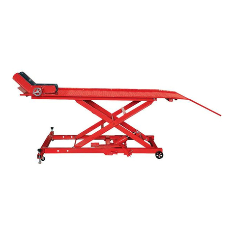
Neilsen CT5511 User manual

1800LBS WHEEL LIFT CT5511
ORIGINAL INSTRUCTIONS
Cannon Tools Limited
Address: 20 Station Road, Rowley Regis, West Midlands, B65 0JU.U.K.
SAVE THESE INSTRUCTIONS AND PRECAUTIONS.

EC DECLARATION OF CONFORMITY
We CANNON TOOLS LTD
20 Station road, Rowley Regis, West Midlands,B65 0JU.U.K.
Declare that the following machine complies with the appropriate basic safety
and health requirements of the EC Directive based on its design and type, as
brought into circulation by us.
In case of alteration of the machine, not agreed upon by us, this declaration will
lose its validity.
Product description: 1800LBS WHEEL LIFT
Model: CT5511
Applicable EC Directives:
EC Machinery Directive 2006/42/EC
Harmonized standards
EN 1494:2000/A1:2008
20 Station Road, Rowley Regis, West Midlands, B65 0JU.U.K.
Mr. Gurcharan Tony Singh Sanghera
Managing Director
CANNON TOOLS LTD
2020-11-25

1. SPECIFICATIONS
Car Lift Capacity: 1800LBS/816 kg
Cargo Deck loading capacity : 300 kg
Cargo Deck size: 60 x 44 cm
Stroke: 730mm
Mimimum height : 70mm
Minimum Tire Diameter: 50 cm
Maximum Tire Width : 30 cm
2. SAFETY INSTRUCTIONS
Before operating the lift, please read the manual carefully and understand it. It is
strictly forbidden to change the safety devices on the wheel lift. Failure to comply
with regulations the manufacturer will be released from all responsibility for any
resulting damages.
The operator must understand the specifications about this product as
explanation of maintenance, operation manual and maintenance manual and
keep the manual carefully for using in the future.
2.1. General Safety
Jack is only used for lifting and can not be used as support.
The device should be operated by two people. It is necessary that the operator
should observe the jack and load during movement.
It is forbidden to lift people.
No change on the jack.
Keep the markings in original state.
As tampering with abnormal last on the jack the jack should be inspected in time.
In this case it is recommended to send the product to authorized service center
for inspection.
Ensure adequate level space around the vehicle for the operator and the lift.
Apply grease, if not apparent, to the carriage rollers, main upright guides,
sprockets and duplex chain to assist the smooth action of the lifting and lowering.
DO NOT operate the vehicle lift if parts are damaged or missing as this may
cause failure and/or personal injury.
Before commencing lift, make a visual inspection of the vehicle lift to ensure
there is no sign of fractured welds, bent adaptors or loose fixings. If found, do not
use the unit and refer to your local dealer for advice and replacement parts.
Tighten loose fixings.

Before commencing lift ensure all vehicle tyres are correctly inflated and the
vehicle sills and bodywork is structurely sound.
Before commencing lift ensure vehicle wheels are locked, chocked or hand
braked.
Observe the following Instructions:
•Only use original spare parts.
•Never exceeding the allowable load capacity (see Specification).
•Observe accident prevention regulations.
2.2. Safety Warnings
A. The lift should be supported on a solid, level and horizontal surface which is
well illuminated and free of obstructions. Never stand the lift on a surface which
may sink.
B. Never exceed the lift’s Rated Capacity.
C. Ensure that there are no persons inside the vehicle to be lifted. Switch off the
engine and apply the brake. If the vehicle has automatic stop/start or is electric
only - ensure the vehicle key is a safe distance from the vehicle to prevent it
activating by mistake. Ensure the vehicle or element to be lifted is safe against
any type of sliding. Use chocks if appropriate . Do not enter the vehicle or start
the engine whilst it is supported on the lift or appropriate stands. The lift is a lifting
device only and should never be used to move the vehicle.
D. During raising and lowering of the load, all precautions should be taken to
avoid movement of the vehicle load.
E. The lift should be positioned so as to avoid the need for the user to introduce
any part of his/her body underneath the vehicle. Never work under a raised
vehicle without supporting it with axle stands or other appropriate methods.
Never position any part of your body near the movable elements of the lift.
F. It is necessary for the operator to be able to observe the lifting device and the
load during all movements. In the presence of dangerous conditions, such as
movement of the vehicle, etc, the lifting process must be stopped immediately
and not attempted until the vehicle is fully secured for lifting.
G. Ensure that there are no persons or obstructions underneath the vehicle prior
to lowering.
H. Always use the locking bar at the nearest locking position under the wheel
cradle when the vehicle is at the required height.

3. TECHNICAL DESCRIPTION
1. wheels
2. frame
3. wheel gripper
4. wheel support
5. splint
6. platforms with safety bolts

4. UNPACKING AND CHECKING
Carefully remove the product from the packaging and examine it for any sign of
damage that may have happened during shipping. Lay the contents out and
check them against the parts shown below. If any part is damaged or missing;
please contact the dealer and do not attempt to use the lift.
Check the following accessories in the pack.
5. ASSEMBLE /INSTALLATION
Assemble
1.Assemble two wheels on the frame.
2.Put the platforms into the splints.
3. Tighten the both splints on the frame.
4. Take the lift mechanism between the both splints.
The lever should be in direction of guide rollers.
The forks should be in direction of fixed rollers.
5.Align the splints and lift mechanism in order to put the long screw through the
gable area.

6.Make sure that the forks sit under the platforms.
7.Assemble the gable area.
8.Assemble the both wheel grippers on the platforms.
As connecting make sure that there are washers between nut and basic material.
Installation
The ground must be level, dry and free of grease. Make sure that the ground can
take the load.
Make sure that there is a safety distance about 3 m around the the lift in order to
have enough place for escaping from dangerous area.
6. OPERATION
Before each operation
1.Make sure that all fastened screws should be tightened sufficiently.
2.Inspect the connection and the state of rollers.
3.Inspect the connection and the state of lift mechanism.
4.Inspect all the moving parts used to switch the moving procedures if there is
enough grease for lubrication.
5.Take a lifting test without load:
Inspect if the mechanism, the switch and the moving parts are in perfect
condition and working properly.
Check the level-lifting function and level-lowering function.
Operation
lifting/Tipping
1. Push the wheel gripper onto a wheel. Select the heavy side of the vehicle as
wheel in the vicinity of motor.
2. Make sure that nobody stays danger area.
3. Switch the lift mechanism onto lifting.
4. Move the level completely from top position to bottom position. The load will
be lifted.
5. Insert the safety bolts in the next effective hole which reachable under the
platform.
6. Repeat step 4 and 5 until the desired high.
7. Never enter the area under the vehicle without sufficient and stable support.

Lowering
1. Switch the lift mechanism onto lowering.
2. Move the level completely from top position to bottom position. The load will
be lowered.
3. Insert the safety bolts in the next hole below.
4. Repeat step 2 and 3 until the desired lower.
Operating with more lifts
Operating with 2 lifts (Lifting an axle) or 4 lifts (Lifting a complete vehicle) we
suggest the 2 or 4 persons move the lifts in same time.
If you are working alone proceed as follow.
1. Position 2 wheel lifts on 2 opposite wheels or 4 wheel lifts on all 4 wheels.
2. In case of lifting and lowering with 2 wheel lifts press the level maximum 2
times and change to opposite wheel lift after safety bolts inserted.
3. In case of lifting and lowering with 4 wheel lifts press the level maximum 1
time and change to next wheel lift in the order after safety bolts inserted.
4. Repeat the procedures in the same order.
5. Never enter the area under the vehicle without sufficient and stable support.
7. MAINTENANCE
IMPORTANT: Both the maintenance and repair of the lift may only be performed
by qualified persons, who have sufficient knowledge of the systems used in
these devices as a result of their training and experience.
2. Keep the lift clean and lubricate all moving parts at regular intervals, which
must be clean and protected from aggressive conditions at all times.
3. Only original spare parts should be used.
4. Prior to each use, check for bent, broken, cracked or loose parts. Do not use if
any defects are present. If it is suspected that the lift has been subjected to
abnormal loads or has suffered any knocks, withdraw it from service until the
problem has been rectified.
5. Following a period of prolonged intensive use, it is recommendable to change
the oil in order to extend the useful life of the lift.
6. Keep the lift in a clean, dry place and out of children reach.

8. PROBLEMS, CAUSES AND REMEDY
In this Table you can find problems occurred during the operation.
The manufacturer is not liable for any damage to person, animal and property if
the handling carried out by non-authorized person.
Problem
Cause
Remedy
The wheel lift can not lift.
Lift mechanism does not
switch.
•Lift mechanism
switches to lifting.
The wheel lift can not
lower.
Lift mechanism does not
switch.
•Lift mechanism
switches to lowering.
Lift mechanism can not
switch.
No sufficient lubrication
in lift mechanism
Lubricate lift mechanism
The wheel lift can not
move under the wheel.
Load plate is still
mounted.
•Disassemble load
plate.
Difficult to push the
wheel lift
Impassable area
No sufficient lubrication
in wheels
Select level floor surface
9. EXPLANATION OF SYMBOLS
Warning! Wear suitable foot protection.
Warning! Wear suitable eye/face protection.
Warning! Read the instruction manual.
Secure vehicle tires with wheel chocks!
Do not stand under lifted loads!

Never exceed the Max. load capacity.
10. EXPLODED VIEW


CANNON TOOLS LTD
Add: 20 station road, Rowley Regis, west midlands,B65 0JU.U.K.
Made in China
Table of contents
Other Neilsen Lifting System manuals
Popular Lifting System manuals by other brands

Atlas Escalateurs
Atlas Escalateurs VISTA installation manual

Columbus McKinnon
Columbus McKinnon Yale HTP Series Translated Operating Instructions

REMA
REMA QPM Series owner's manual

stellar labs
stellar labs Flex Series owner's manual

ATH-Heinl
ATH-Heinl Comfort Lift 2.30 a/s operating instructions

Sumner
Sumner GH5T Operator's manual

Handicare
Handicare SystemRoMedic SlingBarSpreader M manual

Aqua Creek Products
Aqua Creek Products F-03EZPLNA Installation, assembly and operation manual

Rotary
Rotary SM40 operation & maintenance

warequip
warequip Brewer Patient LiftMate Installation & operation manual

Blue Giant
Blue Giant H7012 Installation & technical manual

Sealey
Sealey DH03.V2 instructions