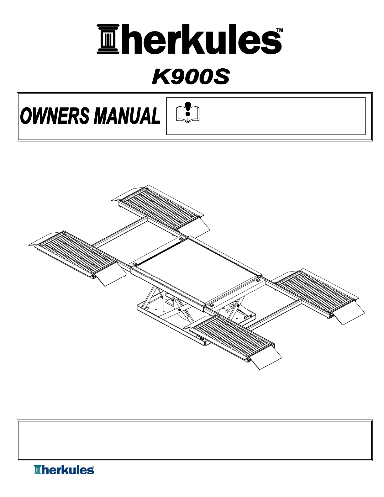
HERKULES K900S User manual
Part# 1002861-04
11/30/2016
This manual contains important information concerning the
installation and operation of the automobile lift listed above.
Read manual thoroughly and keep for future reference
INSTRUCTIONS
Herkules Equipment Corporation 2760 Ridgeway Court Walled Lake, MI 48390-1662 USA
248-960-7100 800-444-4351 Fax 248 960-7109
Patents USA 7070167 4793369, 4960142, 5174317, 5193561, 5485860 Canada 1299468 & Patents Pending
website: www.herkules.us Made in the USA e-mail: info@herkules.us
Page 1 of 16
Warnings ……………………………………………………………………………………………………………………… 2 - 5
Installation ………………………………………………………………………………………………………………….. 6
Duty Cycle ………………………………………………………………………………………………………………….. 7
Operation ……………………………………………………………………………………………………………………. 7 - 8
Maintenance Instructions ……………………………………………………………………………………………………….8
Troubleshooting ……………………………………………………………………………………………………………… 9
Optional Accessories …………………………………………………………………………………………………… 10
Parts List ……………………………………………………………………………………………………………… 11
Controller Layout ……………………………………………………………………………………………………………… 12
Internal Valve Layout ……………………………………………………………………………………………………………… 13
Installation of Suspension Kit ……………………………………………………………………………………………………… 14
Model Information & Schematic ……………………………………………………………………………………………………………… 15 - 16
Serial Number
Model Number
Purchase Date
Distributor
The limited liability warranty applies to the pneumatic chambers of our Herkules lifts and to the initial user against defective
materials for a period of five years from the proof of purchase date. The limited liability warranty applies to other
components of our Herkules lifts to the initial user against defective materials for a period of one year from the proof of
purchase date.
This warranty does not apply to equipment damaged from accident, abuse, overload, misuse, negligence, improper
installation, abrasive or corrosive materials, or shipping damage.
In the event of failure, the defective item must be returned, freight prepaid, to the Herkules manufacturing plant for repair
or replacement. If repairs are required Herkules will not be liable for these repairs to take place in the field regardless
of the application. Proof of purchase and date of purchase must be confirmed. An RGA number (Return Goods
Authorization) and written approval from Herkules must be obtained before any goods can be shipped to Herkules. Herkules
reserves the right to determine whether the cause of failure is due to defective material, normal wear, and/or other causes.
There are no warranties which extend be
y
ond the description on the face hereof. Herkules disclaims an
y
warranty of merchantability or fitness for a particular purpose in connection with the Buyer’s purchase
of any Product under this agreement. Damages are limited to the sales price of the Herkules system.
The terms and conditions herein represent the entire agreement between Herkules and the Buyer.
Any prior / future representations do not apply.
Table of Contents
Warning Symbol Caution Symbol
Limited Liability Warranty
CAUTIONWARNING
This symbol alerts you to the possibility of serious
injury or death if you do not follow the instructions.
This symbol alerts you to the possibility of damage to or
destruction of equipment if you do not follow the
instructions.
This product has patent protection under
one or more of the following patent numbers:
7070167, 5485860, 5193561, 5174317
4960142, 4793369, 1299468
and Patents Pending
website: www.herkules.us
1002742
PATENT NUMBERS
Page 2 of 16
THIS MANUAL CONTAINS IMPORTANT INFORMATION CONCERNING THE INSTALLATION AND
OPERATION OF VEHICLE LIFTS.
WE OFFER TWO SUGGESTIONS:
• READ ALL MANUALS THOROUGHLY BEFORE INSTALLATION.
• KEEP ALL MANUALS FOR FUTURE REFERENCE.
1 Do not exceed the rated load capacity of the lift.
2 Do not continue to push the control lever after lift is fully raised, even though safety valve will prevent
over-inflation of air bag.
3 Use lift only on level surfaces.
4 Keep clear of lift while it is in motion.
5 Do not use air supply exceeding 120 PSI.
6 Do not leave a vehicle raised on the lift overnight.
7 Do not operate lift with defective Control assembly.
8 Never for any reason put arm or any other body part inside lift.
1 Herkules will not be held responsible for any personal injury and/or property damage due to
owner/operator failure to follow the warnings and cautions listed in this manual.
2 Read and understand all warnings, cautions, instructions and manuals before operating this equipment.
3 It is the owner/operators responsibility to maintain the legibility of all warning and instruction labels.
4 DO NOT alter or modify any part of this equipment.
5 DO NOT attempt to bypass the safety lock system.
6 DO NOT tamper with pressure relief valve system inside the lift.
7 DO NOT operate lift while person(s) are in the vehicle
8 ALWAYS check equipment regularly for proper operation and repair or replace worn or damaged parts
immediately.
9 ALWAYS remove damaged lifts from service until repairs are made to the unit. Use only manufacturer's
approved parts and accessories.
Warnings
WARNING
CAUTION
WARNING
CAUTION
WARNING
CAUTION
Page 3 of 16

Tags - Operating Instructions
Warning:
This symbol alerts you to the possibility of serious injury or death if you do not follow
the instructions
Caution:
This symbol alerts you to the possibility of damage to or destruction of equipment if
you do not follow the instructions.
I. Tag - Operating Instructions (P/N 1006355) Front
Page 4 of 16

I. Tag - Operating Instructions (P/N 1006355) Back
II. Tag - Operating Instructions - Air (P/N 1006356)
Page 5 of 16
Locate lift on a level surface in a position most convenient for the loading and unloading of vehicles.
Obtain hose clamps
ID Part # Description Qty.
1 1000166 CLAMP HOSE WIDE BAND #8 SS/Z 1
2 720-122 CLAMP HOSE # 4 SS/Z 1
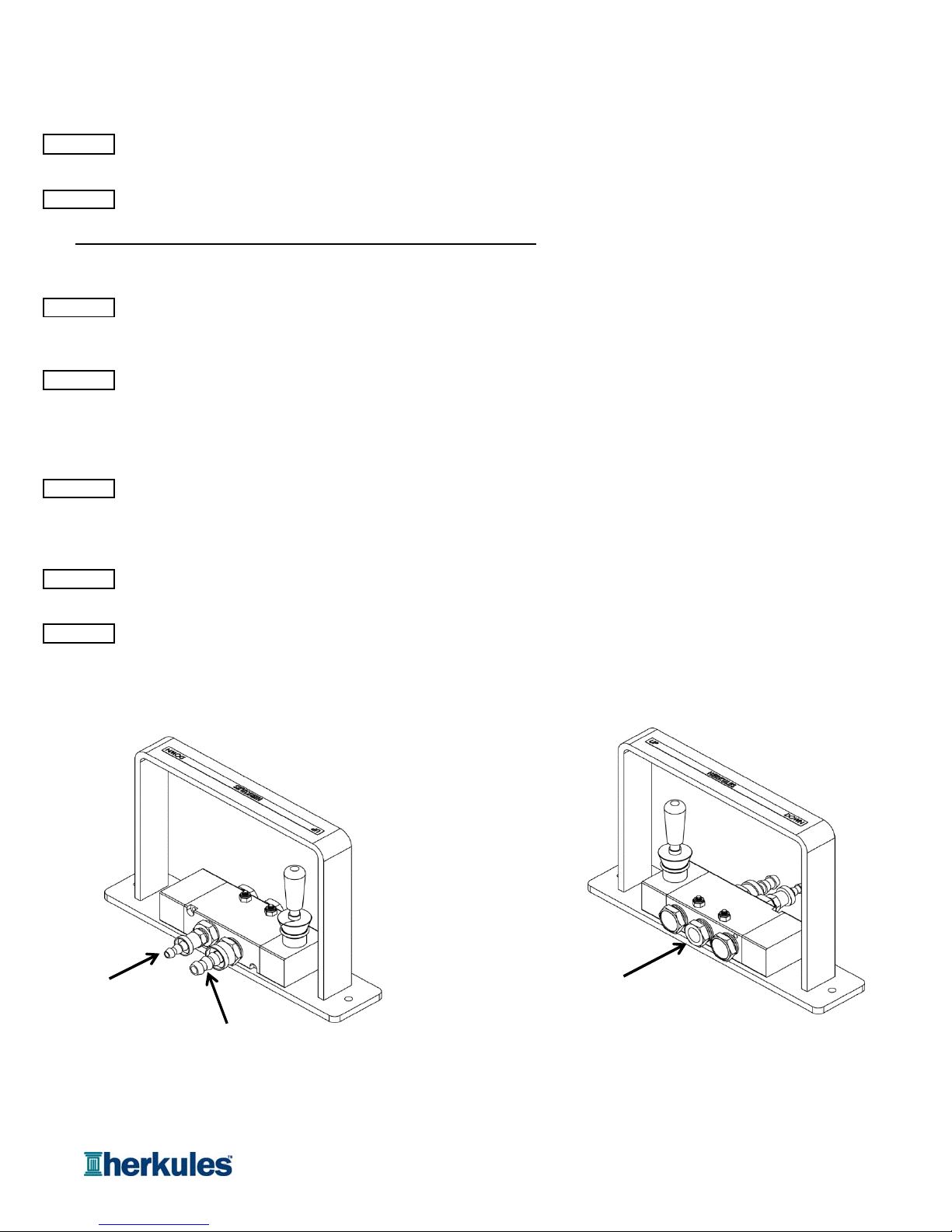
Using the hose clamp (1000166), clamp the 3/8" ID air line from the lift to 3/8" hose barb on the hand control
assembly (see fig.1).
Using hose clamp (720-122), clamp the 1/4" ID air line from the lift to hose barb (1004805) on the hand
control assembly (see fig.1).
NOTE: Check these connections periodically to prevent leakage.
Obtain 1/4 NPT connector compatible with the quick disconnect on your shop air line.
NOTE: Connector not supplied with lift.
Install 1/4 NPT connector into open port (Port 1) on hand control valve (see fig.2).
Connect your shop air line to connector and test for proper operation.
NOTE: Must use clean, dry air only. Herkules recommends using a filter/regulator (see Optional Accessories).
fig 1 fig 2
STEP 7
STEP 1
STEP 2
STEP 3
STEP 4
STEP 5
STEP 6
Installation
3/8" Hose barb
Port 1
1/4" Hose barb
Page 6 of 16

I. Lift Cycle Rating:
This lift is rated for 1 - 5 cycles per day maximum. For high cycle usage warranty does not apply.
II. Duty Cycle:
This lift is rated for approximately 7,000 - 10,000 cycles between repairs (MTBF). This lift is not rated for high duty cycles.
Items that will need repair may include: 1) air bag, 2) safety ratchet, 3) scissors, 4) pivots, and 5) valves.
For heavy duty scissor lift systems that requires little maintenance Herkules recommends our Herkules Ball Screw or Belt
Drive Scissor Lift Systems. These lift systems are designed and manufactured for high duty cycles and long life.
Herkules recommends our electric Ball Screw or Belt Drive lift system for high cycle applications.
Check the weight of the vehicle to be sure that it does not exceed the rated load capacity of the lift: 5,000 lbs.
Drive the vehicle over the first set of ramps and onto the second set of ramps so that all four tires are on the lift, and position the
vehicle so that the vehicle is centered by weight over the center of the lift. Once the vehicle is in the desired position,
set the parking brake of the vehicle.
To raise the lift, move the lever of the hand controller assembly into the UP position. Hold the lever in the UP position
until vehicle has reached the desired working height, then release. The mechanical safety arms will automatically
fall into position as the lift rises.
Do not continue to push the control lever after lift is fully raised, even though safety valve will prevent
over-inflation of air bag.
NOTE: Check the stability of the vehicle during the lifting process, and when vehicle is at desired working height.
If vehicle is unstable, immediately stop the lifting process, slowly lower the lift and reposition vehicle.
To lower the lift, move the lever of the hand controller assembly into the DOWN position. Hold the lever in the DOWN
position until the lift is completely lowered and the wheel platforms are resting on the ground. The mechanical safety arms
will swing up during descent.
NOTE: Check the stability of the vehicle during the lowering process. If vehicle is unstable, immediately stop and
diagnose the issue before continuing to lower the lift.
Operation
STEP 1
STEP 2
STEP 3
STEP 4
Duty Cycle
Page 7 of 16

Once the lift is completely lowered, drive the vehicle off of the lift.
Check clamps and hose connections periodically for tightness to prevent air leakage.
Make sure all moving parts are clean and unobstructed by foreign objects.
Clean filter element every 3 months if applicable.
Grease and oil pivot points once every 3 months.
Lubricate daily if lift is in high cycle application.
Use 90-weight gear lube (SAE 85W 140 EP) to lubricate the pivots and shafts once every 3 months or as needed.
Grease the upper and lower wheel channels every 3 months or as needed.
Lubricate lock mechanism pivot points every 3 months or as needed.
Use overhead rigging when any maintenance beyond external lubrication is required.
STEP 7
STEP 8
STEP 2
STEP 3
STEP 4
STEP 5
STEP 5
Maintenance Instructions
STEP 6
STEP 1
fig.3
Page 8 of 16

Problem Possible Solution
Lift will not go up 1Check that air inlet is connected to the controller.
2 Check to ensure lockout is not engaged (if purchased as option).
3 Check air hoses to ensure no kinks or cuts in the line.
4Check to ensure no debris is preventing wheels from rolling in track.
5 Check regulator gauge is set to minimum of 80 psi (if purchased as option).
Lift is making a hissing noise 1 Check all air lines to ensure they are properly connected and
no leaks are occurring.
2 Check pressure relief valve.
If pressure relief valve is "leaking" lower lift immediately. The air bag
is in a state of over pressurization.
3 Check air bag for cuts or holes.
Lift is making a squeaking noise 1 Lubricate center joints and wheel tracks.
Troubleshooting
Page 9 of 16

ID Part # Description Qty Units
1 12848 Control Valve Assembly - Hand - Lift Only - 2 x Muffler 1 EA
2 12849 Control Assembly - Hand - Lift Only - Wall Mount 1 EA
3 12850 Control Assembly - Hand - Lift Only - Pedestal Mount 1 EA
4 12851 Filter / Regulator Assembly 1 EA
5 12852 Filter / Regulator / Lock Out Assembly 1 EA
6 1002450 Lock Out Valve 1 EA
- 12368 Set of (4) Rubber Blocks - 3-7/8 x 5 x 1-1/2 1 EA
- 12369 Set of (4) Rubber Blocks - 3-7/8 x 8 x 1-1/2 1 EA
Optional K900S Accessories
3
2
1
4
5
6
Page 10 of 16

Part # Quantity Units
17047 1 EA.
16929 2 EA.
16930 2 EA.
16925 2 EA.
16928 2 EA.
17043 1 EA.
15244 1 EA.
10253 1 EA.
693-103 8 EA.
009-126 8 EA.
1000498 8 EA.
009-131B 4 EA.
009-131A 4 EA.
009-137B 2 EA.
009-124 6 EA.
008-113A 4 EA.
10377 2 EA.
720-122 1 EA.
1000166 1 EA.
300-001 1 EA.
10037 1 EA.
M00 1 EA.
009-151 4 IN.
17048 1 EA.
1000505 2 EA.
100-334 225 IN.
100-333 228 IN.
1002968 2 EA.
009-125 1 EA.
009-153 1 EA.
1006323 2 EA.
1006222 1 EA.
1000082 1 EA.
1002860 1 EA.
BOLT HEX 9/16-12 X 2 GD 5 Z
WASHER 9/16 SAE F/W ZINC
NUT JAM 9/16-12 Z
NUT LOCK 9/16-12 Z
SCISSOR ARM WLDMNT C 2-1/2 X 39-3/4
SCISSOR ARM WLDMNT G 2-1/2 X 35-3/4
SCISSOR ARM WLDMNT A 2-1/2 X 39-3/4
SCISSOR ARM WLDMNT E 2-1/2 X 35-3/4
TOP PAN WELDMENT 38-1/4 X 58-1/4
KIT SUSPENSION K900 & K900P
SAFETY CYLINDER ASSY FOR LIFT
WHEEL 40 MM PLASTIC
BOTTOM PAN WELDMENT 37 X 49-1/16
Parts Layout
STICKER BOX LIFT MODEL & SERIAL
ACCELERATOR VALVE ASSEMBLY
MUFFLER 3/8 AIR EXHAUST
TUBE 1-1/4 CLEAR
LIFT CONTROLLER ASSY KIT
CAP 1.0 ID PE BLACK
Description
DECAL MAXIMUM CAPACITY 6000 LBS
DECAL HERKULES LIFT 5.25 X 14.5
OWNERS MANUAL K900
HOSE 3/8" PUSH TO LOK
HOSE 1/4" PUSH TO LOK
TUBE COILED 5/32 OD X 6 NYLON
HERKULES LIFT SERIAL TAGS
BOLT FHSC 5/8-11 X 5 CUT 3.25 BLACK
WASHER FLAT 5/8 SAE Z
NUT LOCK 5/8-11 Z
BOLT ASSEMBLY - CUT AT 3.125
INSTRUCTION LABEL FOR LIFT
CLAMP HOSE # 4 SS/Z
CLAMP HOSE # 8 SS/Z
AIR BAG - K-900
Page 11 of 16
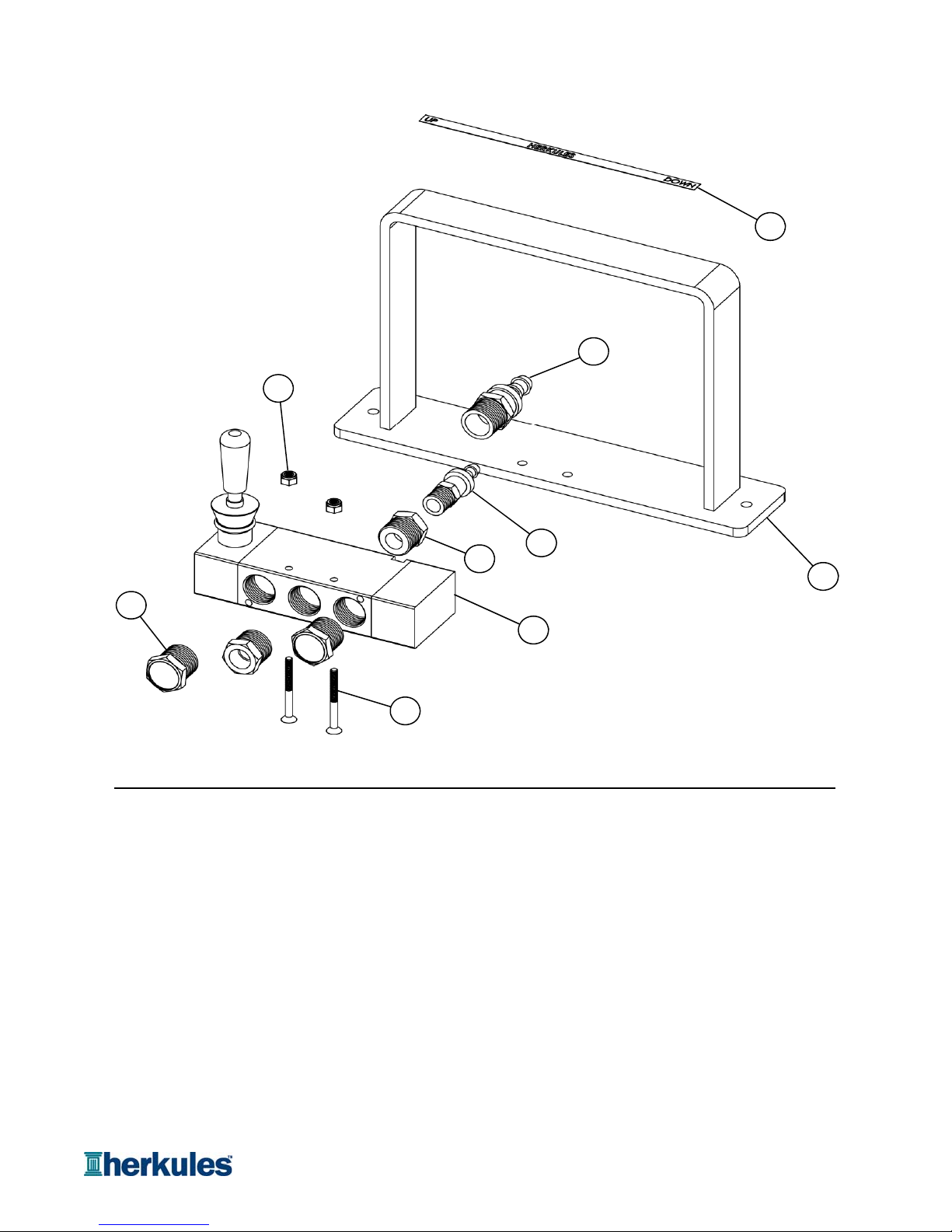
ID Part # Qty Units
1 1002449 1 EA.
2 17049 1 EA.
3 1000078 1 EA.
4 1003585 1 EA.
5 002-172 2 EA.
6 1004805 1 EA.
7 66B 2 EA.
8 1004798 2 EA.
9 1001602 2 EA.
NOTE: Entire controller assembly is part number 14857.
HOSE BARB PTL 3/8 X 1/2 NPT
NUT NYLOCK 8-32 Z
Controller Layout
SCREW FHSC 8-32 X 1-3/4 BLACK
VENT BREATHER 1/2 FOR LIFT CONTROLS
VALVE HAND P5 POS 3 SC OC 1/2 NPT
HAND CONTROL WELDMENT
STICKER UP HERK DOWN .625 X 7
Description
HOSE BARB PTL 1/4 X 1/4 NPT BRASS
RED BUSHING 1/2 NPT X 1/4 NPT BRASS
4
1
2
3
5
6
7
9
8
Page 12 of 16

ID Part # Qty Units
1 009-141 1 EA.
2 M00 1 EA.
3 009-151 4 IN
4 1000166 1 EA.
5 720-122 1 EA.
6 700-112 1 EA.
7 1007872 1 EA.
8 T4 2 EA.
9 1003288 1 EA
10 M6 1 EA.
11 61A 1 EA.
12 M25C 1 EA.
13 1006006 1 EA.
14 C12D 1 EA
NOTE: Entire internal valve assembly is part number 10037.
VALVE 4-WAY PILOT 3/8 NPT BLACK
TEE STREET 1/8 NPT BRASS
Internal Valve Layout
MANIFOLD BLOCK 2 X 2 X 1-1/2 ALUM
Description
FITTING PTC 5/32 X 1/8 NPT
HOSE BARB PTL 1/4 X 1/8 NPT
ELBOW STREET 1/8 NPT BRASS
PLUG SOCKET 3/8 NPT BRASS
NIPPLE HEX 3/8 NPT BRASS
HOSE BARB PTL 3/8 X 1/8 NPT BRASS
MUFFLER 3/8 AIR EXHAUST
TUBE 1-1/4 CLEAR
CLAMP HOSE # 8 SS/Z
CLAMP HOSE # 4 SS
VALVE PRESSURE RELIEF 1/2 NPT 3.5 BAR
1
2
3
5
4
6
7
8
9
14
10
11
13
12
Page 13 of 16
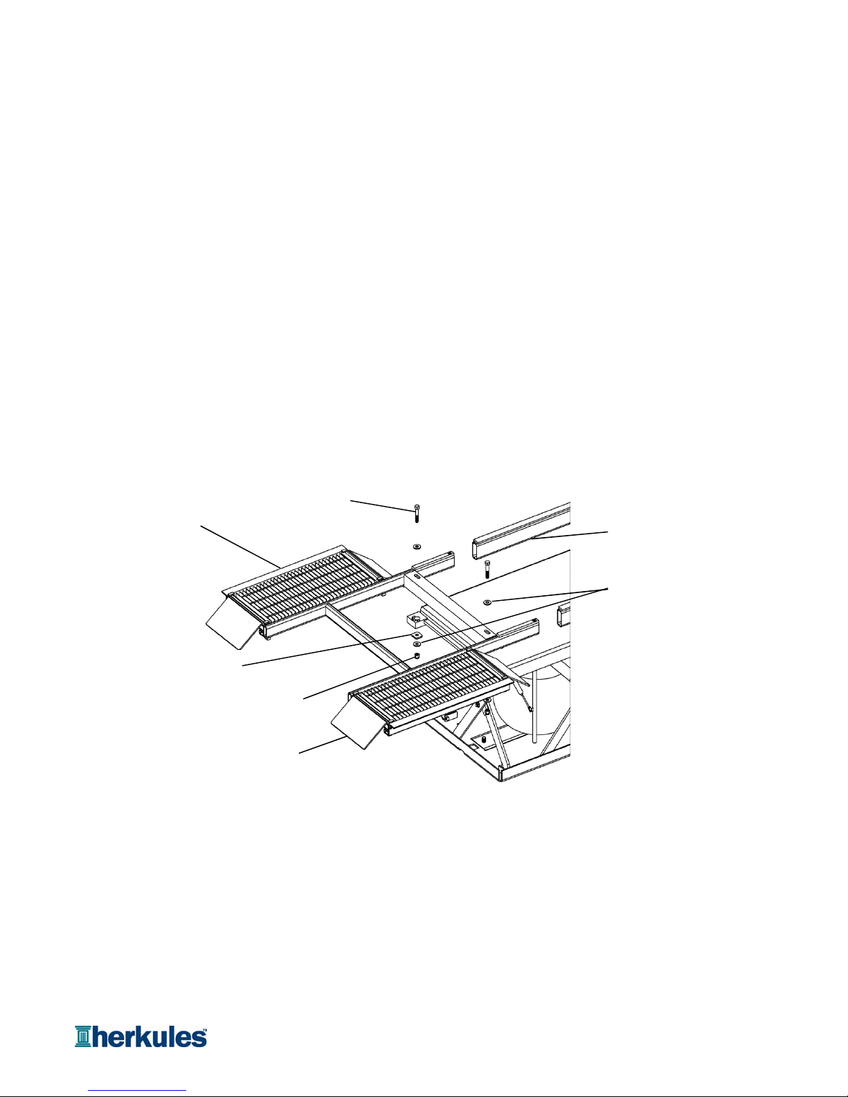
1. Layout the components of the 15244 KIT around the lift.
3. Position one side of the wing brackets over the appropriate lift blocks (see fig. 1).
4. Bolt the wing brackets to the lift as shown in fig. 1.
5. Slide the two tubes (#15247) into position on each side of the wing.
6. Slide the other wing into the tubes and line the mounting bracket over the lift blocks as shown in fig. 1.
8. Bolt the second set of wing brackets to the lift as shown in fig. 1.
9. Replace the old maximum capacity sticker with the new sticker. A stationary lift has 5000 lb. lifting capacity
after the 15244 KIT is installed.
10. Attach two ramps (10148) to each wing assembly (see fig. 1).
Installation of Suspension Kit
Wing 15244 Kit
(P/N 15245) Tube
Assembly
(P/N 15247)
Flat Washer
(P/N 009-125)
Hex Bolt
(P/N 1006319)
Ramp
Assembly
(P/N 10148)
Hex Nut
(P/N 1000241)
Flat Washer
(P/N 15260)
Page 14 of 16

Model Information
Page 15 of 16

Page 16 of 16
Table of contents
Other HERKULES Lifting System manuals

Popular Lifting System manuals by other brands


Discount Equipment
Discount Equipment SKYJACK SJ3013 Operation manual

Tractel
Tractel AH10-40 manual

twin busch
twin busch TW236M Installation, operation and maintenance manual

Sunex Tools
Sunex Tools 6616 owner's manual

Braun
Braun CENTURY NCL 02 Series Service manual

Haklift
Haklift LYKA1006 Translation of the original instructions

WMH Tool Group
WMH Tool Group JET TSLT-770 Operating instructions and parts manual

BorMann
BorMann BWR5218 user manual

Vestil
Vestil LLW Use and maintenance manual

Ravaglioli
Ravaglioli RAV232 NL manual

MAC TOOLS
MAC TOOLS LFMR6 Installation, operation and maintenance manual

RITE-HITE
RITE-HITE RHH owner's manual