Nemesis UMT-2D User manual

Nemesis Audio 1
UMT-2D/UMT-2Di v2.0 USB MIDI TRIGGER
Overview
The Nemesis UMT-2D/UMT-2Di range of trigger boxes are USB MIDI class compliant devices
designed to easily interface external GPI and MIDI signals to any Windows or Macintosh
Operating System environments.
The devices are pre-programmed to generate MIDI messages on receipt of closed contact
events at the GPI connectors.
The UMT-2D/UMT-2Di range can also be used as a USB-MIDI interface providing physical
MIDI IN/OUT to the host computer via a compatible breakout connector, or provide access
to the button generated MIDI events when in Standalone Mode.
The UMT-2Di is fitted with additional GO and STOP buttons as well as a rotary encoder to
eliminate the need for an external control button box.
Connections
GO, STOP XLR: 3 Pin Female XLR connections, designed to interface a remote button
connected via a long cable run, such as a multicore. Switch contact is made by connecting
pin 2 to GND (pin 3). Pin 1 is also connected to GND. These inputs are internally reverse
voltage protected to try and avoid accidents with cross connected patches common with
multicore cables, communications lines, etc.

Nemesis Audio 2
9-PIN GPI: 9-PIN Female D-SUB connector, for connecting 8 GPI signals, primarily local
‘button boxes’, such as GO, STOP, PREV, NEXT boxes for operator controls. Switch contact is
made by connecting pins 1-8 (GPI 1-8) to GND (pin 9). Note that these inputs do not have
the same input protection circuitry as the XLR sockets.
MIDI: 9-PIN Female MINI-DIN connector, for physical MIDI IN/OUT via breakout cable.
Functions as a physical route for MIDI between the host OS and the outside world. Note that
the GPI messages generated by the buttons are merged with the MIDI IN signal to the host.
The breakout connector and cable is capable of supplying 2 independently driven MIDI Out
streams, though only 1 input stream is supported by the device (IN 1, OUT 1+2).
USB: USB Type B Connector for connecting the Windows/Macintosh Host. The device uses
class compliant drivers so shouldn’t need any specific drivers to install. See installation guide
later in this manual.
ACT: Activity Monitor. Illuminates Green during normal device operation. Flashes briefly Red
to indicate MIDI/GPI activity, and during power up cycle.
PWR: Power Monitor. Illuminates Green when the device is powered and enumerated by
the host operating system. If running the unit in standalone mode, this indicator will remain
Red.
GO and STOP buttons (UMT-2Di only): 2 in-built buttons for use as GO/STOP when the unit
is not connected to a suitable button box. Can also be used as additional buttons with a
button box connected.
Rotary Encoder (UMT-2Di only): A multi-turn encoder to rapidly generate MIDI Messages.
Each clockwise turn will generate one message, anti-clockwise clicks will generate a
different message (see MIDI Table for exact messages generated).
Standalone Operation
The UMT-2D/UMT-2Di are capable of running in a ‘standalone’ mode, without the need for
a host operating system.
In this mode, power is provided to the device via a suitable USB power adaptor, and the
power monitor will remain Red to indicate the system is powered, but no enumerated host
connected.
Any GPI MIDI events will then be present at the physical MIDI I/O connector (Outputs 1+2
on the breakout cable). MIDI IN in this mode is not supported.
Nemesis Audio 3
Connection to Host Operating Systems
Connect the UMT-2D/UMT-2Di to the host systems USB port using a standard USB A-B
cable.
After the devices power cycle, ACT should remain Green and the PWR monitor should
illuminate Green once the host has enumerated the device. At this stage the host should
begin driver installation.
Connect a Nemesis REM1, REM89 or custom remotes as required.
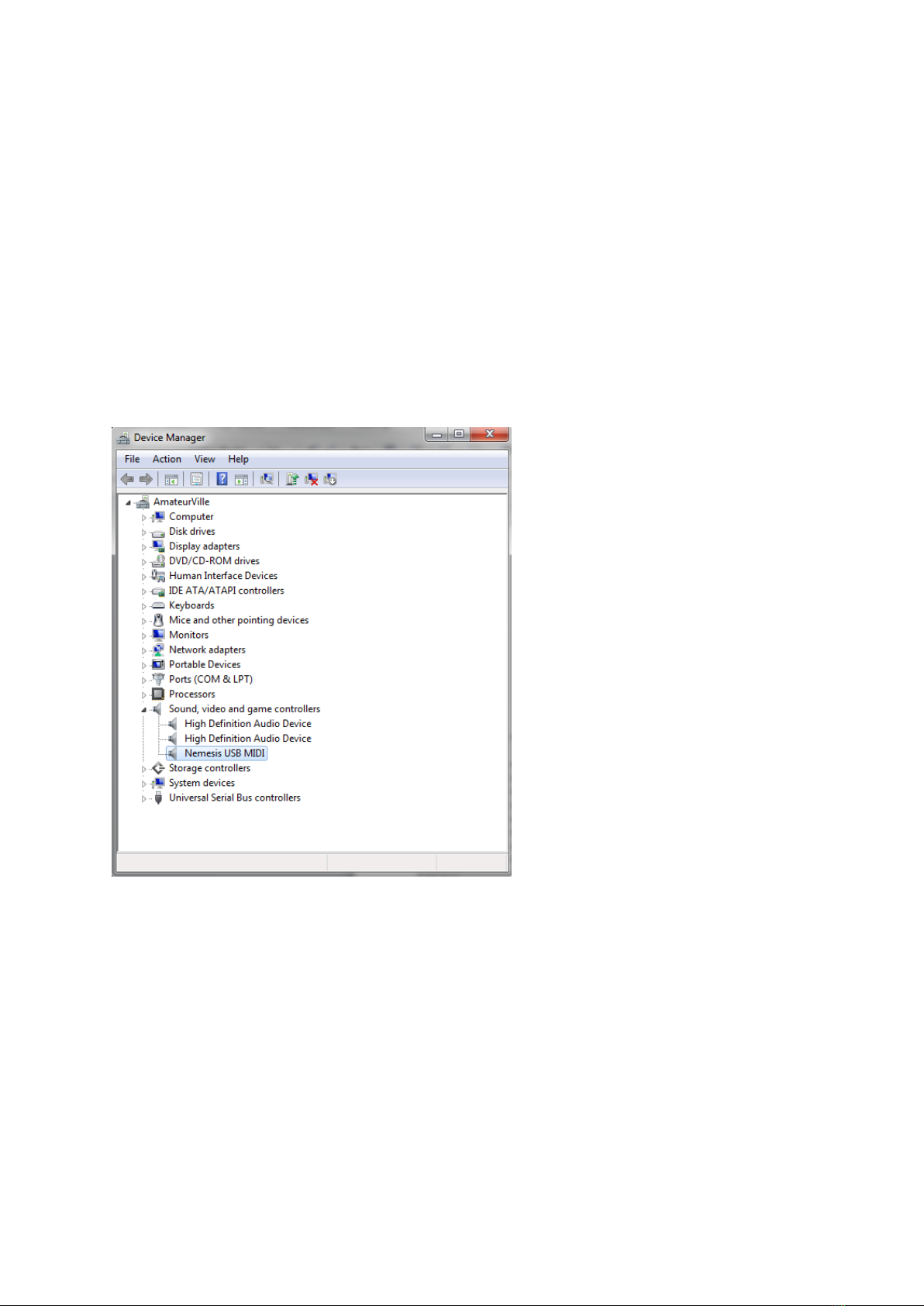
Connection to Microsoft Windows 7/8/10
Windows 7/8/10 will detect the device and attempt to install it a standard USB MIDI device. It may
connect to the internet to determine whether there is a driver to use other than the standard MIDI
driver, but will be satisfied to use the standard class compliant driver.
Windows Device Manager will display the device as “Nemesis USB MIDI”.
Setup in a Program like CTR Electronics “CSC Show Control”
The UMT-2D/UMT-2Di will appear as a standard MIDI device in any software capable of reading and
writing to available MIDI ports.
In both inputs and outputs the device “Nemesis USB MIDI” should be present.

Nemesis Audio 4
Connection to Apple OS X
Once the device has been enumerated, OSX should install the device as a standard class compliant
MIDI device. To check this has been successful, the device will be seen in the MIDI Studio (Window -
> Show MIDI Window) part of Audio MIDI Setup found in Applications->Utilities.
Nemesis Audio 5
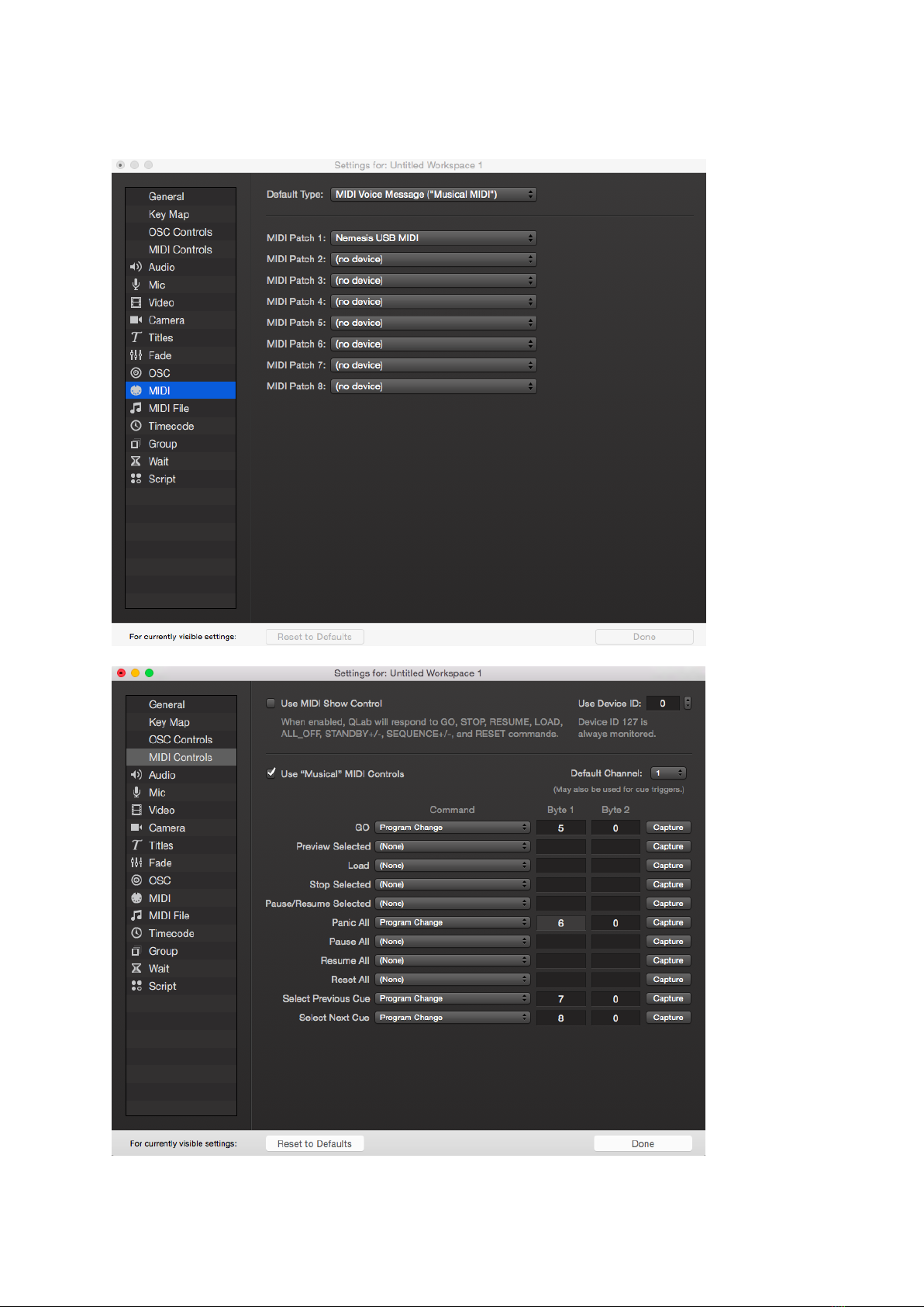
Setup in a program like Figure 53 “Q-Lab”
Nemesis Audio 6
Technical Specifications
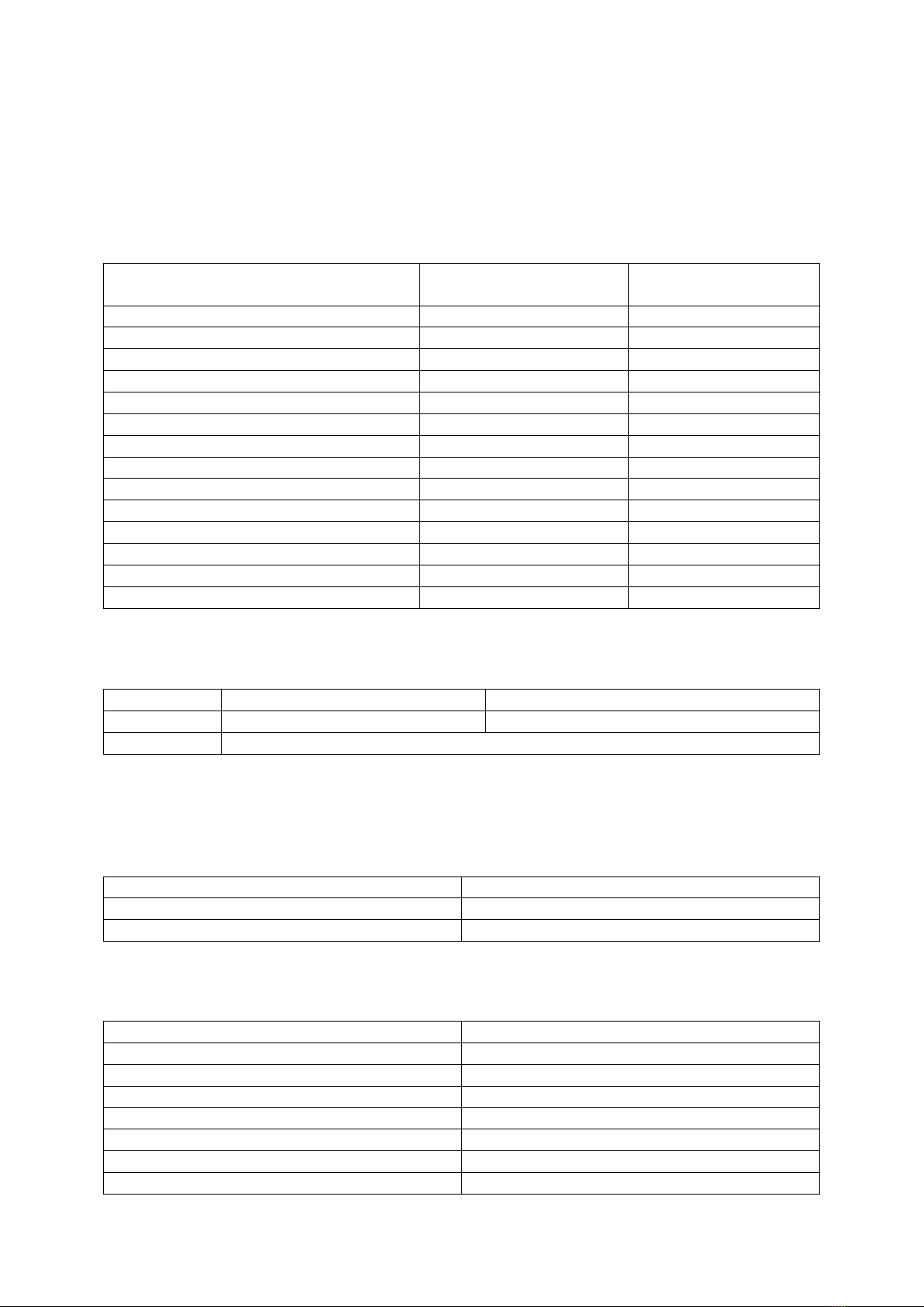
MIDI Data Format
GPI connections are pre-programmed to generate either Program Change (default) or Note On
Messages. This mode of operation is selectable via internal jumper J1 (see below).
Input
Function Program Change
(Default) Channel 1
Function Note On
Velocity 100 Channel 1
GO XLR
1
1
STOP XLR/Red Button
2
2
Rotary Encoder Anti-Clockwise (UMT-2Di)
3
3
Rotary Encoder Clockwise (UMT-2Di)
4
4
DSUB 1
5
5
DSUB 2
6
6
DSUB 3
7
7
DSUB 4
8
8
DSUB 5
9
9
DSUB 6
10
10
DSUB 7
11
11
DSUB 8
12
12
Green Button (UMT-2Di)
13
13
Red Button (UMT-2Di)
14
14
Internal Jumpers
Label
On
Off
J1
Note on Mode
Program Change Mode (default)
J2
Reserved
Connector Pinout
GO/STOP XLR: 3-Pin Female XLR
Connection
Pin Number
Common (GND)
1,3
Switch
2
GPI Connector: 9-PIN Female D-Sub
Connection
Pin Number
GPI DSUB 1
1
GPI DSUB 2
2
GPI DSUB 3
3
GPI DSUB 4
4
GPI DSUB 5
5
GPI DSUB 6
6
GPI DSUB 7
7

Nemesis Audio 7
GPI DSUB 8
8
Common (GND)
9
MIDI I/O: 9-PIN Mini-Din (e.g. Schurter 4850 range)
Connection
Pin Number
MIDI IN ‘4’
1
MIDI IN ‘5’
3
MIDI OUT ‘4’
4
MIDI OUT ‘5’
7
Dimensions and weight
UMT-2d
Equipment Dimensions (HxWxD): ....................................................................................45x81x134mm
Weight: .........................................................................................................................................0.34Kg
UMT-2di
Equipment Dimensions (HxWxD): ....................................................................................64x81x134mm
Weight: .........................................................................................................................................0.38Kg
Notes:
*The single channel MIDI I/O breakout cable is also available as an RME compatible breakout cable,
RME Part No. BOHDSP9652MIDI) http://www.rme-audio.de/en_products_cables.php#6
**This manual is based on UMT-2D/UMT-2Di firmware V2.1.0
Revision 2.0 04/05/16 RC.
Revision 2.1 23/10/18 BA.
Revision 2.2 23/08/19 BA.

Nemesis Audio 8
EU declaration of conformity (CE symbol)
This declaration applies to
- UMT-2d, UMT-2di 4001xxxxx
manufactured by Nemesis Audio
All products of type UMT-2d/UMT-2di starting from variant 4001 are included, provided
they correspond to the original technical version and have not been subject to any later
design or electromechanical modifications.
We herewith declare that said products are in conformity with the provisions of the
respective EC directives including all applicable amendments.
A detailed declaration is available on request and can be ordered from Nemesis Audio.
WEEE Declaration (Disposal)
Electrical and electronic equipment must be disposed of separately from normal waste at
the end of its operational lifetime.
Please dispose of this product according to the respective national regulations or
contractual agreements. If there are any further questions concerning the disposal of this
product please contact Nemesis Audio.
Nemesis Audio
c/o Orbital Sound Ltd
57 Acre Lane
London
SW2 5TN
United Kingdom
- END OF DOCUMENT -
This manual suits for next models
1
Table of contents
Popular Media Converter manuals by other brands


Cross Technologies
Cross Technologies 2015-03A instruction manual

Arec
Arec DS-H2U Quick installation guide

Riello
Riello E 5202 Installation, use and maintenance instructions

Conrad Electronic
Conrad Electronic 197257 operating instructions

Manhattan
Manhattan 205146 Quick install guide

GRASS VALLEY
GRASS VALLEY SONATA - datasheet


