IQDMSES SECTION 11C
IQDMSESOPS 09/01/2008 www.snellwilcox Version 1 Issue 8 11c.4
Features
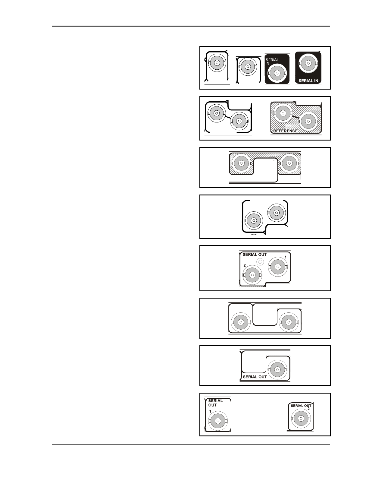
Signal Inputs
Serial Digital........................1 x Equalized SDI
Standards............................SMPTE 259M-C-1997
Reference input...................Composite or black burst
Signal Outputs
Serial Digital........................Up to 2 x reclocked SDI
Standards............................SMPTE 259M-C-1997
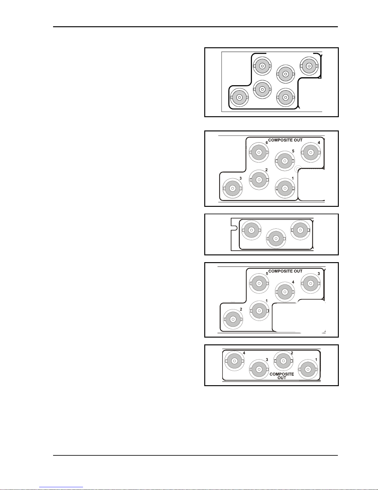
Composite...........................Up to 5 x encoded outputs
Standards............................PAL/NTSC//NTSC-J/PAL-M
/PAL-N/SECAM
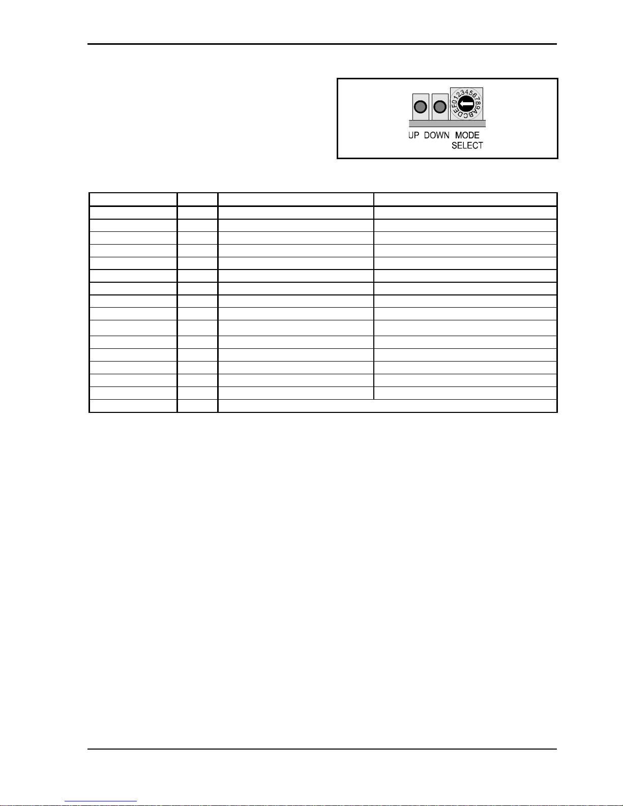
Card Edge Controls (also available via RollCall)
Standard - ...........................PAL/NTSC//NTSC-J/PAL-M
/PAL-N/SECAM
Test pattern select...............Black, Color bars, various test lines
VITS Insert..........................On/Off
Vertical Data........................Pass/Strip
Genlock Mode.....................Internal (Min Delay) lock/ Zero ScH
Lock
Genlock H-Phase offset......±1.9 lines
Genlock Fine H-Phase Offset
1cycle of subcarrier
Genlock SC Phase Offset 360°
SECAM Notch.....................On/Off
SECAM Carrier ...................On/Off
SECAM Pre-Filter................On/Off
NTSC Pedestal ...................On/Off
Blanking Width....................Normal/Legal minimum to CCIR
624
RGB Limiter.........................On/Off
Gain.....................................±0.5 dB
Preset Unit ..........................On
EDH.....................................Present : error second : error hour
Indicators
Power Supplies OK
No Input
No Reference
ScH Error ...........................Output or Reference ScH error
Synchronizer Delay.............Flashes if >1 ms
EDH ....................................Present, Second Error, Hour Error.
Functions Available via RollCall™ Only
Logging ...............................Input change/EDHScH Error
EDH Monitor........................Show/Reset Statistics
RollTrack™ Compatible
Specifications
Reference Input Standard...525/625 (same standard as D1
input)
Composite or Black Burst Reference Level
Standard level ±3 dB
Serial Input Return Loss......Better than -15 dB to 270 MHz
Serial Output Return Loss...Better than -15 dB to 270 MHz
Composite Encoding...........12-bit
Y Frequency Response.......5.5 MHz ± 0.05 dB
U/I and V/Q Frequency Response
<-3 dB @ 1.3 MHz >20 dB at
4.0 MHz
Differential Gain .................Better than 0.2%
Differential Phase ...............Better than 0.2°
ScH Phase..........................0° ±2° (or variable in Variable ScH
Locked Genlock mode)
Composite Output Return Loss
Better than 35 dB to 5.8 MHz
Delay (minimum delay mode)
<4 µs
Power Consumption
Module Power Consumption 7.5 W max
EMC Performance Information
Environment .......................Commercial and light industrial E2
Peak Mains Inrush Current
following a 5 second mains
interruption
No mains input
Performance Information.....No performance degradations or
cable length limitations