Neomatica ADM700 3G User manual


Neomatica, LLC. Terminal ADM700 3G GLONASS/GPS. Ed. 7.2, dd. 24.11.2018
2
Table of contents
1 Application and operation principles ..................................................................................5
2 Technical features ...................................................................................................................7
3 Design ........................................................................................................................................9
4 Tracker operation rules........................................................................................................12
5 Installation procedure..................................................................................................................12
6 Tracker setting ............................................................................................................................14
6.1 Phone number authorization ................................................................................................15
6.2 Server connection settings...................................................................................................15
6.3 Data transmission settings ...................................................................................................16
6.4 Setting coordinates freezing during a parking ......................................................................16
6.5 Using the microSD memory card as a “black box” ...............................................................17
7 Extra equipment connection........................................................................................................17
7.1 Analogue inputs....................................................................................................................17
7.2 Pulse inputs..........................................................................................................................19
7.2.1 «Frequency meter» mode..............................................................................................19
7.2.2 «Flowmeter» mode ........................................................................................................20
7.2.3 «Differential flowmeter» mode .......................................................................................21
7.2.4 Discrete input.................................................................................................................22
7.3 Discrete outputs....................................................................................................................23
7.4 RS-485 Interface ..................................................................................................................27
7.4.1 Working with a digital fuel level sensor ..........................................................................27
7.4.2 Working with the EUROSENS DELTARS sensor..........................................................28
7.4.3 Working with RFID-reader ADM20.................................................................................30
7.5 Interface RS-232..................................................................................................................31
7.5.1 Fuel level sensors connection........................................................................................32
7.5.2 Photo camera connection ..............................................................................................33
7.5.3 CAN-LOG connection....................................................................................................34
7.5.4 Autotracker fuel level sensors connection......................................................................35
7.5.5 Tachograph connection..................................................................................................36
7.6 Working with a headset........................................................................................................37
7.7 1-Wire bus............................................................................................................................37
8 Autoinformer................................................................................................................................38
8.1 Loudspeaker connection ......................................................................................................39
8.2 Routes planning ...................................................................................................................41
8.3 Active route choice ...............................................................................................................43
9 CAN bus (SAE J1939) and CAN-scanner...................................................................................44
9.1 Tracker connection to vehicle CAN-bus................................................................................44
9.2 Can bus data receipt setting.................................................................................................47
9.2.1 Manual setting ...............................................................................................................47
9.2.2 Pre-set parameters usage .............................................................................................48
9.2.3 Available data scanning.................................................................................................48
10 Extra functions settings.............................................................................................................48
10.1 Cellular signal level transmission .......................................................................................48
10.2 Acceleration and braking values transmission....................................................................48
10.3 Alarm system......................................................................................................................49
11 Commands description..............................................................................................................50
12 Tracker software upgrading.......................................................................................................71
12.1 Tracker software upgrading via USB..................................................................................71
12.2 Tracker software upgrading via USB with a firmware file....................................................71
12.3 Tracker software upgrade via GPRS..................................................................................72

Neomatica, LLC. Terminal ADM700 3G GLONASS/GPS. Ed. 7.2, dd. 24.11.2018
3
13 Storage and transportation requirements..................................................................................72
14 Warranty ................................................................................................................................72
15. Marking and packaging............................................................................................................73
16 Disposal....................................................................................................................................73
17 Scope of supply ........................................................................................................................73
Appendix А. Bits description for the «STATUS» field .....................................................................74
Appendix B. WIALON system parameters description...................................................................75
Appendix C. CAN-LOG parameters description ................................................................77
Appendix D. ISO 9001:2015 ..........................................................................................................80

Neomatica, LLC. Terminal ADM700 3G GLONASS/GPS. Ed. 7.2, dd. 24.11.2018
4
This Operation manual relates to the tracker ADM700 3G (hereinafter referred to as tracker)
and describes the procedure of its installation and connection as well as its function and settings.
The Operation manual is designed for professionals who have familiarized themselves with
the rules of repair and installation works execution in vehicles and who have special professional
knowledge in electronic and electric equipment used on various transport means.
The tracker proper work can be guaranteed if it is installed and set by qualified professionals.
To use the tracker properly it is necessary to familiarize with the monitoring system work principles
in general and to understand the function of all its components. For this reason, it is strictly
recommended to get basic knowledge on GLONASS and GPS global navigation satellite systems
functioning, GSM network, issues related to data transmission by means of short message service
(SMS), GPRS and Internet.

Neomatica, LLC. Terminal ADM700 3G GLONASS/GPS. Ed. 7.2, dd. 24.11.2018
5
1 Application and operation principles
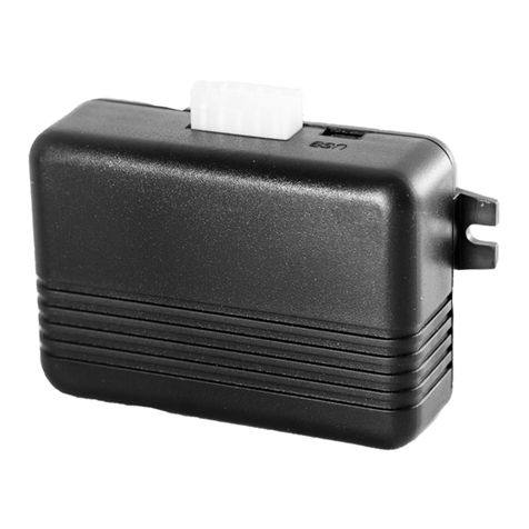
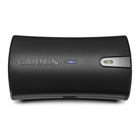
The tracker (see Figure1) is designed for being installed on a vehicle as an extra device
identifying the vehicle location, speed, travel direction. The exterior of the tracker is shown on the
Figure 1.
Figure1 —General view of the tracker
In addition, it records a number of vehicle parameters such as: analogue and discrete inputs
condition and readings from sensors. Similarly, the tracker allows managing external equipment by
means of discrete outputs and with commands received via GPRS or SMS. All the events and
conditions recorded by the tracker are stored in its non-volatile memory.
The accumulated data are transmitted through a mobile operator network of GSM
850/900/1800/1900 standard by means of GPRS batch data transmission to a dedicated server
with static IP-address or domain name, which these data might be received from through the
Internet for further analysis and processing in the operator's console.
The tracker allows establishing voice-connection. When there is an incoming call, the tracker
answers it automatically and establishes voice-connection allowing talking to the driver. To
implement this feature it is necessary to connect a headset or a microphone with a loudspeaker to
the tracker
The tracker might be set by any appropriate method: locally (via USB interface using the
configuration program) or remotely (by means of commands sending via SMS or GPRS).
To secure data integrity while switching the power off and loosing the GSM signal the tracker
is equipped with the non-volatile memory. For the autonomous work the device is equipped with
an inner battery. The working time with the completely charged battery is 3 hours in the full-
featured mode and 2 extra hours in the data saving mode. The working time may change

Neomatica, LLC. Terminal ADM700 3G GLONASS/GPS. Ed. 7.2, dd. 24.11.2018
6
depending on the GSM connection condition. Data transmission is possible only if there is a
mobile connection signal of the GSM 850/900/1800/1900 standard supporting the packet data
transmission (GPRS).
The vehicle travel route is described in the form of separate points in time where all the
information coming to the tracker from inner sensors and extra equipment is recorded. The route
point is saved when at least one event occurs, such as:
−travel direction changes by an angle which is greater than the pre-set one;
−the straight-ahead travel is performed at a distance, which is longer than the pre-set one;
−the pre-set acceleration limit is broken;
−the time for putting the point while traveling (parking) is expired;
−device status change (see the Appendix A);
−an event occurs in analogue and/or discrete inputs.
In this way, route points might be saved with the time interval from one second to several
minutes allowing for a quality routing, recording any changes without a surfeit of information saved
in the “black box” and increase in GPRS traffic.
The tracker with the GLONASS/GPS module ensures time and navigation parameters
measuring based on GLONASS and/or GPS satellites. After being connected to the power supply,
the tracker starts receiving data from satellites, locating itself, identifying speed, time, measuring
voltage in inputs and connecting to the server. After being connected to the server, the tracker
transmits thereto the data packets with the pre-set frequency or when an event occurs. If for any
reason the connection to the server fails, all the information will be saved in the tracker non-
volatile memory and transmitted as soon as the connection is restored.
Data transmitted by the tracker:
⎯GMT date and time;
⎯coordinates (latitude, longitude, altitude);
⎯speed, acceleration and travel direction;
⎯number of satellites when fixing a navigation problem;
⎯precision loss factor in a horizontal plane;
⎯voltage values in analogue inputs;
⎯values from pulse inputs;
⎯data about events occurred;
⎯data from connected sensors;
⎯discrete outputs condition;
⎯device condition (see theAppendixA).

Neomatica, LLC. Terminal ADM700 3G GLONASS/GPS. Ed. 7.2, dd. 24.11.2018
7
If allowed by settings, when there is an incoming call, the tracker establishes voice
connection. During the voice connection data transmission via GPRS is paused and after the first
is finished, the latter will be re-initiated.
2 Technical features
⎯GLONASS/GPS receiver:
chipset: МТ3333 (MediaTek);
frequency band: GLONASS –L1 (СT-code), GPS - L1 (С/Аcode);
sensitivity in cold start/tracking: -148 dBm/-161dBm;
number of tracking/picking-up channels: 33/99;
positioning precision, 95% of time, not worse: 3 m
⎯Connection standard:
GSM 850/900/1800/1900/2100, GPRS/EDGE Multi-slot Class 12/HSDPA 3GPP
release 5
⎯GSM transmitter power: 2 W
⎯Number of SIM-cards: 2 or 2 SIM-chips (optional)
⎯Number of analogue inputs: 6
⎯AIN0 analogue input features:
voltage measurement range 0-6,6V
discreteness (sensitivity) 6 mV.
minimum input resistance 110 kilo-Ohm
⎯AIN1 analogue input features:
voltage measurement range 0-13,3V.
discreteness (sensitivity) 13 mV.
minimum input resistance 110 kilo-Ohm
⎯AIN2...AIN5 analogue inputs features:
voltage measurement range 0-36,6V.
discreteness (sensitivity) 36 mV.
minimum input resistance 110 kilo-Ohm
⎯Number of discrete (pulse) inputs: 2
⎯Discrete (pulse) inputs features:
operation mode: frequency meter, flowmeter (counter), discrete;
maximum frequency: 3000 Hz;
maximum quantity of pulses counted: 4294967295;
activation by connection to the ground;

Neomatica, LLC. Terminal ADM700 3G GLONASS/GPS. Ed. 7.2, dd. 24.11.2018
8
inner pull-up to the plus
⎯Number of “open collector” discrete outputs: 4
⎯“Open collector” discrete outputs features:
maximum voltage - 45V
maximum commutated current –100 mA
⎯RS-485 interface: 1
⎯RS-232 interface: 2
⎯1-Wire Interface: 1
⎯CAN Interface: 1
⎯Push-to-talk plug JACK 3.5 mm: 2.
⎯Linear audio output with “autoinformer” function: 1
⎯Audio output equipped with “autoinformer” function for loudspeaker connection: 1
⎯Acceleration meter type: digital, triaxial
⎯In-built anti-tamper switch
⎯Battery: Li-Pol 1000mA/h 3.7 V (3.7 W/h)
⎯Memory card slot MicroSD: 1
⎯Ingress protection, class: IP65
⎯Mechanical impact protection, class: IK07
⎯Number of route records saved:
when using internal memory: 150000;
when using memory card MicroSD: 8000000 for each GB of memory
⎯PC connection interface: USB.
⎯Operation temperature
1
:
Without battery: -40..+85°С.
With battery: -40..+60°С.
⎯Power voltage: +8..+48 V of unregulated direct current
⎯Current consumption (at the supply voltage 12 V):
maximum: 500 mА
medium: 100 mА
⎯Dimensions: 147х138х25 mm
⎯Weight: not more than 250 g.
1
In order to prolong battery service life its charging start only at 0°С temperature. Data transmission to the server start
at temperature above -40°С.

Neomatica, LLC. Terminal ADM700 3G GLONASS/GPS. Ed. 7.2, dd. 24.11.2018
9
3 Design
The tracker consists of a microcontroller, non-volatile memory, GLONASS/GPS-modules,
GSM-module, RS-485 digital interface, RS-232 digital interface, 1-Wire digital interface, CAN
digital interface, analogue (discrete) inputs, pulse (discrete) inputs, discrete outputs, an
acceleration meter, a memory card interface.
GLONASS/GPS module is used for receiving signals from satellites of GLONASS/GPS
systems and receiver antenna positioning (latitude, longitude and altitude) as well the exact GMT
time, travel speed and direction.
GSM/GPRS module installed in the tracker has the following functions:
⎯Setting and maintaining the outbound TCP/IP connection (receiving and transmitting data in
GPRS mode);
⎯SMS messages receiving and sending;
⎯Incoming voice call receiving and voice connection setting.
For data transmission GSM/GPRS module establishes and maintains connection to the
server and from time to time transmits information packets. Time of data transmission to the server
during the vehicle parking and movement is different and might be changed by the user.
For displaying the working condition, the tracker has got 3 LED indicators: red, green and
blue.
Red LED indicator displays presence/absence of the tracker external power supply. When
the external power supply is there, the light is always on.
Green LED indicator displays the GLONASS/GPS module condition:
−blinks four times: GLONASS/GPS module is switched off because of the low battery and
the external power supply cut off;
−blinks three times: GLONASS/GPS module is switched on but no data have been received
from it yet;
−blinks twice: data from GLONASS/GPS module have been received but coordinates are not
valid;
−blinks once: GLONASS/GPS module has defined the time and the valid coordinates.

Neomatica, LLC. Terminal ADM700 3G GLONASS/GPS. Ed. 7.2, dd. 24.11.2018
10
Blue LED indicator displays the GSM/GPRS module condition:
⎯blinks four times: GSM module is switched off because of the low battery and the external
power supply cutoff;
⎯blinks three times: GSM module is switched off for reinitialization;
⎯blinks twice: GSM module is switched on but there is no connection to the server;
⎯blinks once: the tracker has installed connection to the server and is successfully
transmitting information packets;
⎯is always lighting up and switching off for short moments: SIM-card is not available.
See the contacts arrangement for MF-24F plug of the tracker in Figure 2.

Neomatica, LLC. Terminal ADM700 3G GLONASS/GPS. Ed. 7.2, dd. 24.11.2018
11
Figure 2 —Contacts arrangement (12 +U vehicle (electrical system)

Neomatica, LLC. Terminal ADM700 3G GLONASS/GPS. Ed. 7.2, dd. 24.11.2018
12
4. Tracker operation rules
Tracker installation should be performed by persons familiarized with operation principles,
item design and this Operation Manual. When using the tracker, the staff should follow the
recommendations according to safety precautions applied while working with consumers' power
units.
It is forbidden:
−to use the tracker in any conditions different from those described in relation to the tracker
technical features.
−to use tracker with damage and/or liquid penetration signs.
−to open the tracker case when it is under voltage as well as to open its case by someone
who does not have necessary qualification, did not familiarize with operation principles, item
design and this Operation Manual.
−to clean the tracker with any aggressive liquids, solvents, chemical or abrasive agents
capable to harm its case, energy-supply elements, fixing system or disturb proper function of the
tracker in any way. For cleaning it is necessary to use a clean dry cotton tissue or a soft brush.
−Intentionally bring the tracker into condition not previewed by this Operation manual,
technical requirements or other documents describing the tracker operation.
−to use the tracker in cases, which may cause its damage, harm its energy-supply systems,
affect staff's health or use it in any other way causing dangerous situations and financial losses.
After trackers transportation in sub-zero temperatures they should be stored at room
temperature within 24 hours.
5 Installation procedure
The internal GLONASS/GPS and GSM antennas are used in the tracker, which allow for its
installation almost in any place of the vehicle. However, it is not recommended to install it in the
places where the received signals will be attenuated by the vehicle metallic housing, since this
may affect the tracker operation quality.
Before installation, it is necessary to install a SIM-card with activated data transmission
service via GPRS, SMS and sufficient balance for these services. Then the power is supplied to
the MF-24F connector wires: the plug contact 12 is connected to the positive voltage of the
vehicle electrical system, the plug contact 24 –to the negative voltage of the vehicle electrical
system (housing, GND). Contacts arrangement layout for MF-24 connector is provided in the
Figure 2. It is necessary to install a 2A melting fuse between the positive ground of the vehicle

Neomatica, LLC. Terminal ADM700 3G GLONASS/GPS. Ed. 7.2, dd. 24.11.2018
13
electrical system and the tracker 12 contact plug. Install the melting fuse as close as possible to
the vehicle electrical system entry because this is very important when connecting to the battery
tracker. Connection layout for the tracker power supply is provided in the Figure 3.
When the power supply is properly connected, the green and blue LED will have been
blinking many times during five seconds. When there are valid data from satellites and the
connection to the server is installed, the tracker will identify time, coordinates and transmit
information packets to the server, which will be announced by a single green and blue LED
blinking.
It is strictly recommended to carry out a preliminary check of the tracker operation condition
under laboratory conditions using instead of the vehicle electrical system laboratory power source
ensuring the output voltage from 10V to 40V of the direct current and at least the 1A current.

Neomatica, LLC. Terminal ADM700 3G GLONASS/GPS. Ed. 7.2, dd. 24.11.2018
14
Figure 3 - Typical connection layout for the tracker power supply (12 +U vehicle electrical system)
6 Tracker setting
The tracker is controlled by means of commands sent via SMS, GPRS or USB.
General rules for writing commands:
⎯only Latin alphabetic characters and punctuation may be used in commands;
⎯character case does not matter;

Neomatica, LLC. Terminal ADM700 3G GLONASS/GPS. Ed. 7.2, dd. 24.11.2018
15
⎯commands transmission syntax is the same for SMS, GPRS and USB;
⎯all commands syntax: «CMD X1,…,X3», where CMD is a command, X1..X3 are commands
parameters.
⎯commands are separated by a SPACE. Parameters are separated by commas, except for
the DN0 command which parameters are separated by a colon.
After receiving a command, the tracker executes it and sends a feedback.
If the command parameters extend beyond the acceptable range, the tracker changes them
to the nearest acceptable values. If it is not possible to change parameters or parameters are not
enough, the tracker will answer with an error message. The command without parameters will
restore to the current settings.
To set the terminal via USB it is necessary to install the ADMConfigurator program available
at the website http://neomatica.com If a password has been set, it should be entered immediately
after connection in the respective ADMConfigurator program window. If the tracker works with a
default password (“0”), it is not necessary to enter the password.
No authorization is required for configuration via GPRS.
6.1 Phone number authorization
To handle the tracker via SMS-commands it is necessary to send the SMS command «ADD
ME 0» to the SIM-card number installed in the tracker, where 0 is the default password. If the
password has been changed, the new one should be indicated. The phone number, which
such a command is sent from, will be authorized in the tracker. In response, an SMS
containing the authorized phone numbers list will be sent. If a wrong password is
entered, the SMS will not be sent, and the command will be disregarded. The
authorized phone numbers list might be requested with the «PHONES» command.
The authorized phone numbers list is stored in non-volatile memory. The maximum quantity
of phone numbers saved is 4. Clearing the authorized phone numbers list is made by restoring to
factory settings.
6.2 Server connection settings
Set APN parameters for the selected mobile operators by the «SETGPRS0» command for
SIM card 0 and «SETGPRS1» for SIM card 1. Then set the IP-address and the server port (host)
by the «SETHOST0» command or «DN0».
These parameters change might be performed in graphical interface of ADMConfigurator
program.

Neomatica, LLC. Terminal ADM700 3G GLONASS/GPS. Ed. 7.2, dd. 24.11.2018
16
6.3 Data transmission settings
Navigation data and the data collected from different sensors, which are sent from the tracker
to the server, are divided into blocks. Depending on the functions used the set of transmitted data
is defined by the «PROTOCOL» command.
Data block compliance with the command parameters values are provided below in the Table
1. If it is necessary to transmit data from several blocks, «PROTOCOL» command parameter is
calculated based on addition. It is possible to use any variants.
For saving traffic it is recommended to activate only necessary data blocks.
For example:
basic data(0)+analogue inputs(8)+fuel level sensors(32)=PROTOCOL 40
basic data(0)+analogue inputs(8)+outputs, events as per inputs(4)=PROTOCOL 12
basic data(0)+pulse inputs(16)+odometer values(128)=PROTOCOL 144
Table 1. Basic parameters values for PROTOCOL command
Data block name
Parameter value
Basic data
NAVIGATION DATA
0
Outputs, events per inputs
OUTS
4
Analogue inputs
IN_A
8
Pulse inputs
IN_D
16
Fuel level sensors
FUEL
32
Can
CAN
64
Odometer value
ODOMETR
128
6.4 Setting coordinates freezing during a parking
The margin of error might cause a slight coordinates dispersion during a long-term parking of
the vehicle. To prevent this effect the coordinates freezing function might be used in the beginning
of the parking. This mode is activated automatically when there is no vibration (installed by default),
or when the discrete level is changed in the analogue input (setting is needed).
The acceleration meter measures the current level of vibration (accelerations sum in three
axis). If the vibration level below the threshold continues more than a minute and half, the tracker
records the last valid coordinates received from GLONASS/GPS module and transmits them to the
server in all further packets. When the vibration level threshold increases more than by 5 seconds,
the coordinates freezing mode is deactivated, and the valid coordinates received from
GLONASS/GPS module are transmitted. The vibration level threshold is installed by the
«MAXACC» command. This mode activation is performed by the INSTATIC 15,1 command.

Neomatica, LLC. Terminal ADM700 3G GLONASS/GPS. Ed. 7.2, dd. 24.11.2018
17
To enable the freezing coordinates function when the vehicle ignition is switched off, it is
necessary to connect to the analogue input a circuit being under voltage when the ignition is on.
This mode activation and input selection are performed by the «INSTATIC» command. For the
analogue input used it is necessary to set values of the logical one «INTRUE» and the logical zero
«INFALSE». In this way, when the ignition is off, an event will be formed in the input and the
coordinates freezing will be initiated.
Switching coordinates freezing on and off during short-term stops is performed by the
«PSTATIC» command. This method does not require extra signal connection to the tracker but
does not exclude a slight coordinates dispersion in adverse conditions for receiving signals from
satellites.
6.5 Using the microSD memory card as a “black box”
The tracker allows using the microSD memory card as a “black box” for saving data
transmitted to the telematic server. For this, it is necessary to put the memory card in the holder
and send the «SDLOG» command. After this, the terminal will be rebooted. It is possible to save 8
million events per each 1 GB of the card. Therefore, it allows saving almost an unlimited route.
The procedure of data extraction to the server is feasible depending on time and relevance. The
procedure is set by the «SERIAL» command.
7 Extra equipment connection
7.1 Analogue inputs
Analogue inputs might be used for analogue sensors connection and voltage level measuring.
Each analogue input might be interpreted as a discrete one.
IN0 input features:
Voltage measurement range: 0-6,6V.
Discreteness (sensitivity): 6mV
The minimum input resistance: 110kOhm
IN1 input features:
Voltage measurement range: 0-13,3V.
Discreteness (sensitivity): 13mV.
The minimum input resistance: 110kOhm.
IN2-IN5 inputs features:
Voltage measurement range: 0-36,6V.
Discreteness (sensitivity): 36mV.

Neomatica, LLC. Terminal ADM700 3G GLONASS/GPS. Ed. 7.2, dd. 24.11.2018
18
The minimum input resistance: 110kOhm.
If the voltage level in a given circuit does not exceed 6,6 V or 13,3 V, it is recommended to
use IN0 or IN1to enhance readings transmission accuracy.
It is prohibited to supply voltage to the input if it exceeds the upper measurement range
threshold by more than 20%.
The current voltage value in the analogue input is displayed in response to the «INPUT»
command.
When it is necessary to smooth the measured voltage fluctuations, it is possible to set the
time of readings averaging by the «INFILTER» command.
When there is a need for recording the fact of a certain voltage presence, for example, in the
ignition activation circuit, it might be necessary to set for the selected analogue input voltage levels
for the logical “0” by the «INFALSE» command and for the logical “1” by the «INTRUE» command
Commands description:
INFALSE IN, X0, Y0
IN –number of the analogue input
X0 –the lower logical 0 range threshold
Y0 –the upper logical 0 range threshold
INTRUE IN,X1,Y1
IN –number of the analogue input (0 or 1)
X1 –the lower logical 1 range threshold
Y1 –the upper logical 0 range threshold
Figure 4 —Discrete states ranges
If the voltage level is in the indifference zone, the previous discrete state will be saved until
the level is beyond the indifference zone.
The measured voltage levels values are registered by the tracker and transmitted to the
server in the data block IN_A with a common periodicity.

Neomatica, LLC. Terminal ADM700 3G GLONASS/GPS. Ed. 7.2, dd. 24.11.2018
19
When the discrete state is changed, an extraordinary packet is sent, and the discrete state is
transmitted in the OUTS data block.
Activate the required data blocks transmission with the «PROTOCOL» command.
7.2 Pulse inputs
Inputs IN6(DIN0), IN7(DIN1) are used for connecting frequency sensors, flowmeters,
including differential ones to the tracker These inputs might be set as discrete inputs with an inner
pull-up to the plus.
Discrete (pulse) inputs operation mode is set by the «IMPULSE X, Y» command
X –DIN0 input mode, Y –DIN1 input mode
Examples:
IMPULSE 0,0 –pulse inputs in the “Frequency meter” mode
IMPULSE 1,1 –pulse inputs in the “Flowmeter” mode
IMPULSE 1,2 –pulse inputs in the “Differential flowmeter” mode
IMPULSE 3,3 –pulse inputs in the “Discrete input” mode
«Frequency meter», «Flowmeter» and «Discrete input» modes might be chosen in any
combination. The «Differential flowmeter» mode works with both inputs.
To transmit data from discrete (pulse) inputs to the server it is necessary to activate the
«IN_D» data block with the «PROTOCOL» command. Depending on the operation mode selected,
the response to the «INPUT» command will contain frequency, flowmeter accumulated values or
current state of the discrete input.
7.2.1 «Frequency meter» mode
The «Frequency meter» mode allows measuring the current signal frequency. It is used when
connecting frequency output sensors. Connection layout for a fuel level output sensor is provided
in the Figure 5.

Neomatica, LLC. Terminal ADM700 3G GLONASS/GPS. Ed. 7.2, dd. 24.11.2018
20
Figure 5 —Connection layout for fuel level frequency output sensor (12 +U vehicle electrical system)
7.2.2 «Flowmeter» mode
«Flowmeter» mode allows counting pulses and saving data in the non-volatile memory. A
layout for connecting two flowmeters to the tracker is provided in the Figure 6.
Table of contents
Other Neomatica GPS manuals
