Neomatica ADM50 User manual

Neomatica. LLC. Tracker ADM50 GLONASS / GPS. Rev.1.2 dated 03.10.2018 1

Neomatica. LLC. Tracker ADM50 GLONASS / GPS. Rev.1.2 dated 03.10.2018 2
This Guide extends to the telematic terminal ADM50 (hereinafter referred as terminal or
tracker), determines the order of its operation, and also contains a description of the tracker
functioning and its management.
Installation and configuration of the tracker should be carried out by qualified specialists to
ensure its proper functioning. For successful application of the tracker, it is necessary to
familiarize with the working principle of the entire monitoring system, and understand the purpose
of all its components separately. Therefore, it is strongly recommended to familiarize with the
basics of the functioning of the global navigation satellite systems GLONASS and GPS, GSM
communications, the features of data transfer via short text messages (SMS), GPRS and the
Internet.

Neomatica. LLC. Tracker ADM50 GLONASS / GPS. Rev.1.2 dated 03.10.2018 3
Table of Contents
1 Purpose and Function..............................................................................................................4
2 Technical specifications...........................................................................................................5
3 Turning on and off....................................................................................................................5
3.1 Turning on and off with the power button.................................................................................5
3.2 Automatic switching-on by the charger connection..................................................................6
3.3 Power button lock....................................................................................................................6
4Indication.................................................................................................................................6
4.1 Green LED - GLONASS/GPS module status ..........................................................................6
4.2 Blue LED - GSM module status...............................................................................................7
4.3 Red LED - battery charge process status................................................................................7
4.4 Determining the battery charge level .......................................................................................7
5Operating Modes.....................................................................................................................7
5.1 Beacon Mode...........................................................................................................................8
5.2 Tracker Mode...........................................................................................................................9
6Functioning of the SOS Button ..............................................................................................10
7Low Battery Warning .............................................................................................................11
8Updating the terminal software..............................................................................................11
8.1 Updating the terminal software via USB...................................................................................11
8.2 Updating the terminal software via GPRS..................................................................................12
8.3 Updating the terminal software via USB using the firmware file.............................................12
9Storage and transportation requirements ....................................................................13
10 Warranty .................................................................................................................13
11 Marking and packaging.............................................................................................13
12 Disposal ....................................................................................................................14

Neomatica. LLC. Tracker ADM50 GLONASS / GPS. Rev.1.2 dated 03.10.2018 4
1 Purpose and Function
The ADM50 terminal consists of a microcontroller, non-volatile memory, a GLONASS/GPS
module, a GSM / GPRS module, an accelerometer, an alarm button.
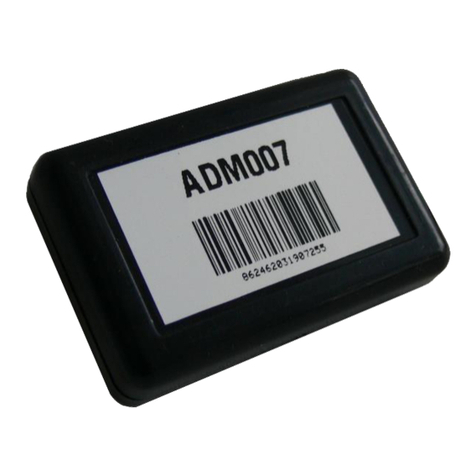
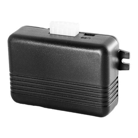
Picture 1 —General view of the ADM50
GLONASS/GPS module is for receiving signals from GLONASS/GPS satellites and
determining the geographical coordinates of the location (latitude, longitude and altitude), as well
as the exact time (GMT), speed and moving direction.
The GSM/GPRS module establishes and supports outgoing TCP/IP connection, periodically
transmitting information packets to a dedicated server with a static IP address or domain name,
and also receives and sends SMS messages by means of GPRS packet data transmission
technology.
The accelerometer is used to determine the level of vibration, which manages switching of
energy-saving functions in the automatic mode.
The "SOS" alarm button is used to activate a mechanism for sending an SMS message and
sending an information packet with the alarm flag to the server.
After switching-on the tracker receives information from the satellites of the GLONASS/GPS
system, determines its location, speed, time and establishes a connection to the server. After
establishing the connection, tracker transmits the accumulated data with given frequency to the
dedicated server, from which it can be received via the Internet for further analysis and
processing with use of corresponding software on personal computers and other supported
computing devices.
In case of absence of communication with the server, the tracker writes information packets
to non-volatile memory, and upon the appearance of the connection, transmits them.
Depending on the selected mode of operation, it is possible to perform the functions of a car
tracker, a personal tracker, or a beacon (bookmark). Tracker can be used to track the location of
any mobile or stationary object - vehicle, cargo, person, animal, etc.

Neomatica. LLC. Tracker ADM50 GLONASS / GPS. Rev.1.2 dated 03.10.2018 5
2 Technical specifications
•GLONASS/GPS receiver: chipset: МТ3333 (MediaTek);
frequency ranges: GLONASS - L1 (CТ-code), GPS - L1 (С/Аcode);
cold start/tracking sensitivity: -148 dBm/-163 dBm;
number of tracking/capturing channels: 33/99;
accuracy of determining the coordinates, 95% of the time, no worse than: 3 m.
•Communication standard: GSM 850/900/1800/1900, GPRS Multi-slot Class 12.
•GSM transmitter power: 2 W.
•Number of SIM cards: 1.
•Accelerometer type: digital, tri-axial.
•Alarm button.
•Li-Po battery: capacity 3000 mAh (11.1 W*h), weight 60 g.
•Number of storable entries about route: 100000.
•PC communication interface: USB.
•Operating temperature in battery discharge mode: -20..+60°C.
•Operating temperature in battery charging mode: 0..+45°C.
•Maximum current consuming in standby mode: to 1 A.
•Charger voltage: 5 V.
•Dimensions: 89х56х25mm.
•Weight: not more than 125 g.
3 Turning on and off
3.1 Turning on and off with the power button
To turn on the tracker, press and hold the power button at least for three seconds. When the
three LEDs begin to glow, you can release the button. The blue and green LEDs will turn off, and
the red LED will produce the flashes series according to the battery charge level (watch section
"Indication" - "Determining the battery charge level"). Tracker switched on.
To turn off the tracker, press and hold the Power button in the pressed state. When the
button is pressed, the three LEDs will light up, and after 3 seconds the LEDs will turn off. Release
the button. Tracker switched off.

Neomatica. LLC. Tracker ADM50 GLONASS / GPS. Rev.1.2 dated 03.10.2018 6
3.2Automatic switching-on by the charger connection
If this function is activated, the inclusion of the tracker is automatic, when it is connecting to
a charger or personal computer. Regardless of how the disabling occurred, using the Power
button or because the battery is completely discharged. By default, this feature is disabled.
The configuration performs locally - using the configurator via the USB interface or remotely
by sending commands via GPRS or SMS.
PENU X
X=0 –Automatic switching-on disabled.
X=1 –Automatic switching-on enabled.
3.3Power button lock
If this function is activated, disabling of the tracker becomes impossible with the Power
button. Even so, switching-on the tracker and the function of determining the battery charge level
are still available. By default, the lock is disabled.
The configuration performs locally - using the configurator via the USB interface or
remotely by sending commands via GPRS or SMS.
POFF X
X=0 –Power button unlocked.
X=1 –Power button locked.
To disable the tracker using the button, you must disable the Power button lock.
Indication
4.1Green LED - GLONASS/GPS module status
•flashes three times during the period - GLONASS/GPS module is on, but there is no data
from it yet;
•flashes twice during the period - there is data from the GLONASS/GPS module, but the data
is invalid;
•flashes once during the period - there is data from the GLONASS/GPS module and the data
is valid;
•no flashes - GLONASS / GPS module is turned off or the ADM50 is in a sleeping state.
In the beacon mode, the LED does not light regardless of the GLONASS/GPS module state
during sleep.

Neomatica. LLC. Tracker ADM50 GLONASS / GPS. Rev.1.2 dated 03.10.2018 7
4.2Blue LED - GSM module status
•flashes three times during the period —cellular network is available, GPRS connection is
not established, connection with the server is not established;
•flashes twice during the period —cellular network is available, the GPRS connection is
established, the connection to the server is not established;
•flashes once during the period —cellular network is available, a GPRS connection is
established, a connection to the server is established;
•no flashes —GSM/GPRS module is turned off or GSM network registration is in progress. It
is also possible in case the ADM50 is in a sleeping state.
In the beacon mode, the LED does not light regardless of the GSM module state during sleep.
4.3Red LED - battery charge process status
•LED flashes once a second —charging;
•LED lights permanently —charging completed;
•LED flashes more often than once a second —the charging process is completed
abnormally. It is possible if the temperature of the device has exceeded the allowed limits,
or the device's charging time has been exceeded;
•LED does not lit —there is no external power. It is possible if the USB cable is not
connected or there is no contact in the USB connector.
4.4Determining the battery charge level
To determine the battery charge level, briefly press the Power button. Thereafter, red LED would
make several flashes, the number of which will correspond to the battery charge level:
•three flashes –maximum charge level;
•two flashes –average charge level;
•one flash –low charge level, you need to charge the battery.
5 Operating Modes
The ADM50 terminal can be in one of two modes: Beacon or Tracker. The operating mode
of the ADM50 can be selected locally by using the configurator via the USB interface or remotely
by sending commands via GPRS or SMS.

Neomatica. LLC. Tracker ADM50 GLONASS / GPS. Rev.1.2 dated 03.10.2018 8
DMODE X
X=0 –Beacon Mode, X=1 –Tracker Mode
5.1Beacon Mode
In the beacon mode, the ADM50 is periodically in the active state, performs certain actions,
such as: determining coordinates, waiting and processing incoming SMS, and others, and
between activity states the tracker is in the sleep state (energy saving).
Beacon mode setting commands:
BTIME X,Y,Z,A
X –minimum activity time;
Y –maximum activity time;
Z –sleep time after successful activity;
A –sleep time after error,
Where X, Y, Z, A sets in seconds.
•minimum activity time - the time during which the ADM50 will guaranteed be in the active
state, even if all the necessary actions were performed. This time allows to wait for an
incoming SMS containing the command;
•maximum activity time —the time after which the ADM50 will go to sleep, even if it didn't
not perform all the necessary actions, for example, determine the coordinates or send data
to the server;
•sleep time after successful activity —the time for which the ADM50 will be in sleep state, if
all the necessary actions were performed during the ADM50 activity;
•sleep time after error —the time for which the ADM50 will be in sleep state, if during the
activity were not executed all the tasks or errors occurred, for example, it was not possible
to establish connection to the server.
BMODE X,Y,Z
X –GSM module status during sleep: 0 –off., 1 –on.;
Y –GLONASS/GPS module status during sleep: 0 or 1 –off.;
Z –determination of coordinates during activity:
0 –Disabled;
1 –GLONASS/GPS;

Neomatica. LLC. Tracker ADM50 GLONASS / GPS. Rev.1.2 dated 03.10.2018 9
2 –LBS;
3 –Auto;
•status of the GSM/GPRS module during sleep - this parameter determines the possibility of
receiving an SMS command during sleep;
•status of the GLONASS/GPS module during sleep - turned off. The ability to turn on the
GLONASS/GPS module during sleep (Y=1) will be implemented soon.
•determination of coordinates during activity - this parameter determines the need to
determine the coordinates during the activity and their source.
«Disabled» (Z=0) – determination of coordinates is not performing, the mode is used for
maximum energy saving. That allows to determine the coordinates only on request. The tracker
establishes a connection to the server during waking, but does not send packets - only waits for
GPRS or SMS command.
«GLONASS/GPS» (Z=1) – determination of coordinates performs only via GLONASS/GPS
system.
«GSM base stations» (Z=2) – determination of coordinates performs only via LBS
technology. This mode of determining the coordinates has lower accuracy than navigation using
GLONASS/GPS systems, but significantly saves battery power.
«Auto» (Z=3) – selecting the source of coordinates is in automatic mode. The priority system
is GLONASS/GPS. In the case if signal strength from satellites is low and the coordinates are not
valid, the location determines by GSM base stations.
BWAKEUP
The command carries out an extraordinary switching the tracker into the beacon mode activity
state. In the sleep state, SMS command WAKEUP will be received and executed if the parameter
X of the BMODE command is 1. Executing the command BWAKEUP causes restart of the sleep
time timers (Z and A parameters) of the command BTIME.
WHERE
The command makes a request for a link to "Yandex.Maps". The response to the command
will be received as a text SMS message containing a hyperlink with the last valid coordinates.
5.2Tracker Mode
In Tracker mode, the ADM50 determines the coordinates every two seconds, filters the
resulting coordinates with a series of filters and if the coordinates satisfy all conditions, generates
data packets and sends them to the server. The algorithm for smart point recording uses the

Neomatica. LLC. Tracker ADM50 GLONASS / GPS. Rev.1.2 dated 03.10.2018 10
parameters set by the PERIOD and TRACK commands (see the Appendix A). In the absence of
communication with the server, the tracker writes information packets to the "black box" and,
upon communication with the server, carries out their unloading. In Tracker mode, the ADM50
never goes into sleep states, but has some energy-saving features.
"Statics" is a motionless device mode. In this mode, the last valid coordinate is fixed, and all
subsequent coordinates are ignored until the movement begins.
"Deep Statics" is a motionless device mode, in which GSM/GPRS and/or GLONASS/GPS
modules can be additionally switched off.
To configure the parameters of the Deep Static mode, available commands are:
TSTIME X
X –The time through which the Deep Static mode activates, in seconds.
TSMODE X,Y
X –the status of the GSM module in the Deep Static mode: 0 - off, 1 - on.
If in the Deep Statics mode the GSM module stay enabled then regardless of the
GLONASS/GPS module status the tracker will send packets with the last valid coordinate to the
server;
Y –the state of the GLONASS/GPS module in the Deep Static mode: 0 - off, 1 - on. The
parameter impacts on the navigation data availability speed when leaving the Deep Statics mode!
6 Functioning of the SOS Button
The SOS button in ADM50 can be triggered by pressing (closing) or releasing (opening).
When the SOS button triggers, activates the processing script, which includes:
•sending SMS with text «device_name ALARM» to the listed numbers. Maximum quantity of
numbers - 4.
•determining the coordinates and sending a packet with the alarm flag to the server. The
device will not exit the SOS processing script state until at least one point with an alarm flag
is sent.
The execution of the SOS button processing script state does not impact on the sleep time
timers of the Beacon mode (parameters Z and A), specified by commandBTIME
To set the operating mode of the SOS button, use the command

Neomatica. LLC. Tracker ADM50 GLONASS / GPS. Rev.1.2 dated 03.10.2018 11
SOSPOL X
X=0 –reaction to pressing the button (closing),
X=1 –reaction to releasing the button (opening).
The commands to work with the list of telephone numbers for sending alarm SMS (no
more than 4 phone numbers are stored):
EventListAdd X
Add a phone number to the list to send alarm SMS,
X –phone number in format «7xxxxxxxxxx»;
EventListClear
Erase all numbers from the list of phone numbers for sending alarm SMS;
EventListShow
Show list of phone numbers for sending alarm SMS.
7 Low Battery Warning
Upon reaching the set voltage level on the battery, an SMS message with the text
«device_name: battery low!» will be sent to authorized by command EventListAdd phone
numbers. The activation of the function and the setting of the critical voltage level is performed
using the command:
BATALARM X,Y
X=0 –alert function disabled, X=1 –function enabled. Y –critical battery voltage level, mV.
8 Updating the terminal software
Terminal software upgrade (firmware) might be performed through the USB-interface by
means of configuration program or via GPRS-channel.
8.1Updating the terminal software via USB
Configuration program checks the valid firmware version in the upgrade server, and if
necessary downloads the firmware file.
To upgrade firmware, do the following:

Neomatica. LLC. Tracker ADM50 GLONASS / GPS. Rev.1.2 dated 03.10.2018 12
-
connect USB cable (miniUSB/USB-A) to the terminal and Personal computer's
USB port;
-
launch “ADMConfigurator” program on personal computer;
-
if a more recent firmware version than the one installed on the terminal is detected,
“ADMConfigurator” program will inform you of its presence;
-
press “Upgrade available”;
-
in the opened tab “Notifications” press “firmware upgrade via USB”;
-
after being upgraded, the terminal will be rebooted and become available for work.
WARNING! Don't switch the terminal's power off when upgrading the terminal's firmware
until the terminal is detected by the setting program. Otherwise there is a risk of damaging the
software whose recovery can be performed only in the manufacturer's office
8.2Updating the terminal software via GPRS
To upgrade the terminal software via GPRS, it is necessary to install an active SIM-card in
the terminal, set the user's access point and mobile operator password (APN, user, pass).
Otherwise, the terminal will have remained in the mode of firmware uploading from the server
until connection attempts are over.
The upgrading process will start after the terminal receives «UPDATE» command via one of
the possible channels USB, GPRS, SMS. After having received the «UPDATE» command the
terminal connects to the upgrade server and uploads the relevant firmware.
After a successful upgrade the terminal passes to the standard operation mode with the
access point and server address settings installed before upgrading. The remained settings
should be checked after upgrade and if necessary, re-install them.
Depending on the GSM-network the upgrading process takes on average from 2 to 5
minutes. If the upgrading upload is not possible, the terminal will continue working with the
existing software.
8.3Updating the terminal software via USB using the firmware file
Firmware file should be requested in technical support.
To upgrade the firmware via the USB interface with a firmware file, do the following:
-
connect USB cable (miniUSB/USB-A) to the terminal and Personal computer's USB port;
-
launch “ADMConfigurator” program on personal computer;after having connected the
terminal to the program, open the “Settings” section in the “Device” tab, press “Flash the
file”;
-
press “Yes” in the popup;
-
drag the firmware file in the respective field in the configurator window;

Neomatica. LLC. Tracker ADM50 GLONASS / GPS. Rev.1.2 dated 03.10.2018 13
-
after the firmware is upgraded, the terminal will be rebooted and become available for work.
WARNING! Don't switch the terminal's power off when upgrading the terminal's firmware
until the terminal is detected by the setting program. Otherwise there is a risk of damaging the
software whose recovery can be performed only in the manufacturer's office.
9 Storage and transportation requirements
Terminals should be stored in a warehouse at a temperature of +5 оC to +40 ºС and relative
humidity at most 85 %.
After terminals' transportation in sub-zero temperatures they should be stored at room
temperature within 24 hours.
10 Warranty
The manufacturer guarantees the terminal proper function within 12 months (built-in battery
- 6 months) from the day of its sale if consumer meets all the requirements and follows all the
rules of transportation, storage, installation and handling.
The warranty does not cover:
•a terminal with mechanical damages and defects (cracks and chips, dents, signs of impacts,
etc.) caused by consumer as a result of handling, storage and transportation rules violation.
When there are signs of oxidation or other proofs of liquid penetration in the device housing;
•a terminal without housing;
•a terminal with signs of repair performed beyond the manufacturer's service center;
•a terminal with signs of electrical and/or other damages caused as a result of unacceptable
changes in external power network parameters or improper use of the terminal;
•a terminal disabled because of an unauthorized software upgrade.
The device software is licensed, terms related to the manufacturer's limited liability in the
framework of the License Agreement are provided at the web site
http://en.neomatica.ru/upload/files/license.pdf
11 Marking and packaging
Marking is placed on the terminal housing. The terminals are packed in individual boxes,
which protect them during transportation and storage. Multipack is possible.

Neomatica. LLC. Tracker ADM50 GLONASS / GPS. Rev.1.2 dated 03.10.2018 14
12 Disposal
Device recycling is performed according to national and local norms and requirements.
13 Scope of supply
Name
Quantity
Terminal ADM50
1
Power Supply - Charger
1
Datasheet
1
Manufacturer: Neomatica LLC 24а
Malkova, office 7, Perm 614087, Russia
Phone: +7 (342) 2-111-500 (ext. 42).
Web-site: http://neomatica.com

Neomatica. LLC. Tracker ADM50 GLONASS / GPS. Rev.1.2 dated 03.10.2018 16
Appendix A. Commands description
№
Command
Response
Parameters
Description
1
Name X
Example:
Name bus8
Device Name ‘X‘
Example: Device Name ‘bus8‘
X –terminal name
Set the name of the terminal. The name can contain
only letters of the Latin alphabet and numbers. The
name cannot exceed 10 characters in length. The
terminal name is added to the alarm SMS messages.
2
ADD ME X,Y
(only SMS)
Example:
ADD ME 1234
ADD ME 1234,2
PHONES (0)= (1)= (2)= (3)=
Example:
PHONES (0)= +79876543210
(1)= (2)= (3)=
PHONES (0)= (1)= (2)=
+79876543210 (3)=
X –password, the default is "0".
Y=0..3 –number of the memory
location to store the number.
Optional parameter.
Authorize the phone number from which the SMS was
received and write it to the memory cell Y. The
command is needed only to create a list of numbers
for controlling the terminal via SMS.
3
PHONES X
Example:
PHONES 1234
PHONES (0)= (1)= (2)= (3)=
Example:
PHONES (0)= (1)=
+79876543210 (2)= (3)=
X –password, the default is "0".
Request a list of authorized phone numbers.
4
STATUS
Example:
ID=1 Soft=0x09 GPS=9291
Time=11:21:39 25.02.10
Nav=0 Lat=57.2359
Lon=56.2593 Speed=0.0
SatCnt=5 Stat=0x0000
Command without parameters.
Current terminal condition.
ID –the number of the terminal (ID=1
always),
Soft –the software version,
GPS –the current number of the information
packet,
Time –current time and date according to
Greenwich Mean Time,
Nav –coordinates validity,
Lat –latitude,

Neomatica. LLC. Tracker ADM50 GLONASS / GPS. Rev.1.2 dated 03.10.2018 17
Lon –longitude,
Speed –speed,
SatCnt –number of satellites,
Stat –status.
5
PASS X,Y
X –the old password by default
X=0.
Y –new password.
Setting password.
6
IMEI
Example:
IMEI
IMEI
Example:
IMEI 359587013832624
Command without parameters.
Request IMEI of the GSM module installed in the
tracker. The command works 20 seconds after
power on.
7
PIN0
Example:
PIN0 1234
PIN0=X
Example:
PIN0=1234
X–PIN code
Setting PIN code for SIM card.
8
PIN1
Example:
PIN1=1234
PIN1=X
Example:
PIN1=1234
X–PIN code
Setting PIN code for SIM chip.
9
SETGPRS0
X,Y,Z
Example:
GPRS0: APN=X, user=Y,
pass=Z
Example:
X –access point,
by default X=internet.beeline.ru Y –
login, by default Y=beeline
Set GPRS parameters for SIM-card. The
command without parameters restores to the
current settings GPRS.
SETGPRS0
internet.beeline.ru
beeline,beeline
GPRS0: APN=
internet.beeline.ru,user=
beeline,pass= beeline
Z –password, by default
Z=beeline

Neomatica. LLC. Tracker ADM50 GLONASS / GPS. Rev.1.2 dated 03.10.2018 18
10
SETGPRS1
X,Y,Z
Example:
GPRS1: APN=X, user=Y,
pass=Z
Example:
X –access point by default
X=internet.beeline.ru Y –login by
default Y=beeline
Set GPRS parameters for SIM-chip. The
command without parameters restores to the
current settings GPRS.
SETGPRS1
internet.beeline.ru
beeline,beeline
GPRS1: APN=internet.mts.ru,
user=mts, pass=mts
Z –password by default
Z=beeline
11
SIMPRIORITY X
SIM PRIORITY X
X=0 –no priority
X=1 –main SIM card
X=2 –main SIM chip
by default X=0
Setting priority between SIM-card and SIM-chip.
12
SETHOST0 X,Y
Example:
SETHOST0
134,236,21,2,123
00
HOST0=X,Y
Example:
HOST0=134,236,21,2:12300
X –IP address, use
commas instead of dots.
Y –server port
Setting IP-address and server port, which the
terminal is connected to for data transmission. The
command without parameters restores to the
current server address and port.
13
DN0 X:Y
Example:
SETHOST0
www.test.ru:1000
HOST0=X:Y
Example:
HOST0= www.test.ru:1000
X –server domain name,
Y –server port
Setting domain name and server port, which the
terminal is connected to for data transmission. The
command without parameters restores to the current
server address and port.
14
DMODE X
Example:
DMODE 1
DMODE=X
Example:
DMODE=1
X=0 –Beacon mode
X=1 –Tracker mode
Selecting current mode of the tracker.

Neomatica. LLC. Tracker ADM50 GLONASS / GPS. Rev.1.2 dated 03.10.2018 19
15
BMODE X,Y,Z
Example:
BMODE 1,0,1
BMODE=X, Y, Z
Example:
BMODE=1, 0, 1
X –GSM module status during
sleep, X=0 –off, X=1 –on.
Y –GLONASS/GPS module
status during sleep, Y=0
–off, Y=1 –on.
Z –determination of coordinates
during activity, Z=0 –no; Z=1
–GLONASS/GPS; Z=2 –LBS; Z=3
–Auto.
Setting the GSM and GLONASS/GPS
modules disabling in Beacon mode.
16
BTIME X,Y,Z,A
Example:
BTIME=X,Y,Z,A
Example:
X –minimum activity
time in seconds.
Setting the duration of activity and sleep states in
Beacon mode.
BTIME
30,180,600,300
BTIME=30,180,600,300
Y –maximum activity
time in seconds.
Z –sleep time after successful
activity.
A –sleep time after error in
seconds.
17
BWAKEUP
BWAKEUP OK
Extraordinary awakening the tracker in the Beacon
mode.
18
WHERE
Request for a link to «Yandex.Maps» with the last
valid coordinates. Answer is in text SMS-message.
19
PERIOD X,Y
Example: PERIOD
60,300
PERIOD min=X max=Y
Example: PERIOD
min=60 max=300
X –recording period during
movement in seconds
Y –recording period in modes
"Statics" in seconds.
Setting the recording period in the memory of
information packets during the movement and in
the "Statics" modes.

Neomatica. LLC. Tracker ADM50 GLONASS / GPS. Rev.1.2 dated 03.10.2018 20
20
TRACK X,Y,Z,A
Example:
TRACK
3,10,300,10
TRACK X,Y,Z,A
Example:
TRACK 3,10,300,10
X –minimum speed
Y –angle in degrees
Z –distance in meters.
A –speed change in km/h/s
Setting the quality of the route drawing. A new point
on the route is setting if the direction of movement has
changed more than by the angle Y or the distance to
the previous point is greater than Z or the speed
change per second is greater than A. This mechanism
is switching off if the speed becomes less than X, in
order to avoid the excess of points at maneuvers at
low speeds, while the period of recording of points will
be determined by the parameter X of the PERIOD
command.
Changing the parameters of the TRACK
command can lead to incorrect work of the
tracker!
21
TSTIME X
Example:
TSTIME 300
TSTIME=X
Example:
TSTIME=300
X –the time, through which the
"deep statics" mode activates,
in seconds.
Setting the time through which the transition to the
"Deep Statics" mode will occur when there is no
movement.
22
TSMODE X,Y
Example:
TSMODE 1,1
TSMODE=X,Y
Example:
TSMODE=1,1
X –status of GSM module,
X=0 –off; X=1 –on.
Y –status of GLONASS/GPS
module,
Y=0 –off; Y=1 –on.
Setting of disabling of the GSM and
GLONASS/GPS modules in the Deep Statics
mode.
23
SOSPOL X
Example:
SOSPOL 0
SOSPOL=X
Example:
SOSPOL=0
X=0 –triggering on press (contact
closure).
X=1 –triggering on release
(contact opening).
Setting the triggering mode of the "SOS" button.
24
POFF X
Example: POFF 0
POFF=X
Example: POFF=0
X=0 –Power button
unlocked.
X=1 –Power button
locked.
Setting the prohibition of disabling the tracker using
the Power button.

Neomatica. LLC. Tracker ADM50 GLONASS / GPS. Rev.1.2 dated 03.10.2018 21
25
PENU X
Example:
PENU 0
PENU=X
Example:
PENU=0
X=0 –Auto power on disabled.
X=1 –Auto power on enabled.
Activation of the automatic turn-on of the tracker,
when connected to a charger or personal computer.
26
BATALARM X,Y
Example:
BATALARM
03650
BATALARM=X,Y
Example:
BATALARM=0,3650
X=0 –function disabled.
X=1 –function enabled.
Y –critical battery voltage
level, in mV.
Setting up of SMS sending for low battery
alarm.
27
EventListAdd X
Example:
EventListAdd
79876543210
Number was added to event
list
Example:
Number was added to event
list
X –adding phone number in
format «7xxxxxxxxxx»
Add a phone number to the list for sending alarm
SMS. List is storing no more than 4 phone
numbers.
28
EventListClear
Event list was cleared
Erasing all numbers from the list of phone
numbers for sending alarm SMS.
29
EventListShow
Event list: (0)=779876543210
(1)=79876543211
(2)=79876543212 (3)=
Request a list of phone numbers for sending alarm
SMS.
30
UPDATE
Start update
Firmware update via GPRS channel.
31
ERASE EEPROM
Reset to default settings.
32
ERASE FLASH
Cleaning the "black box".
Table of contents
Other Neomatica GPS manuals
