Neomatica ADM007 User manual


OOO Neomatica. Terminal ADM007 GLONASS / GPS. Rev.1.3 dated 13.09.2019
2
Content
1 Purpose and Function..............................................................................................................................4
2 Technical specifications..........................................................................................................................5
3 Design...........................................................................................................................................................6
4 Installation...................................................................................................................................................7
5 Setting the tracker.....................................................................................................................................8
5.1 Connecting to the Configurator......................................................................................................8
5.2 Setting using commands...............................................................................................................10
5.3 Setting the connection to the server...........................................................................................11
5.4 Setting data transmission..............................................................................................................11
5.5. Setting route (track) drawing ....................................................................................................12
5.5.1 Selecting presets of route drawing quality........................................................................12
5.5.2 Expert setting of tracking parameters. ...............................................................................13
5.6 Setting the fixation (freezing) of coordinates during the parking.......................................15
5.6.1 Coordinates fixation by the ignition ....................................................................................15
5.6.2 Coordinates fixation by speed ..............................................................................................15
5.7 Operation mode................................................................................................................................15
5.7.1 “Tracker” operation mode......................................................................................................16
5.7.2 “Beacon” operation mode......................................................................................................16
6 Connection of additional equipment..................................................................................................16
7 Description of commands.....................................................................................................................18
8 Upgrading tracker software..................................................................................................................20
8.1 Updating the tracker software via the configurator................................................................20
8.2 Updating the tracker software via the configurator using the firmware file ....................20
8.3 Updating the tracker software via GPRS...................................................................................21
9 Handling and transport regulations....................................................................................................21
10 Warranty obligations............................................................................................................................21
11 Marking and packaging .......................................................................................................................22
12 Disposal...................................................................................................................................................22
13 Scope of supply.....................................................................................................................................22
14 Acceptance certificate .........................................................................................................................23
Appendix A. Description of the field bits«STATUS» .........................................................................24
Appendix B. Description of transmitted parameters in Wialon ..................................25

OOO Neomatica. Terminal ADM007 GLONASS / GPS. Rev.1.3 dated 13.09.2019
3
This Operation manual relates to the tracker ADM007 (hereinafter referred as tracker) and
describes the procedure of its installation and connection as well as its function and settings.
The Operation manual is designed for professionals who have familiarized themselves with
the rules of repair and installation works execution in vehicles and who have special professional
knowledge in electronic and electric equipment used on various transport means.
The tracker proper work can be guaranteed if it is installed and set by qualified professionals.
To use the tracker properly it is necessary to familiarize with the monitoring system work principles
in general and to understand the function of all its components. For this reason, it is strictly
recommended to get basic knowledge on GLONASS and GPS global navigation satellite systems
functioning, GSM network, issues related to data transmission by means of short message service
(SMS), GPRS and Internet.

OOO Neomatica. Terminal ADM007 GLONASS / GPS. Rev.1.3 dated 13.09.2019
4
1 Purpose and Function
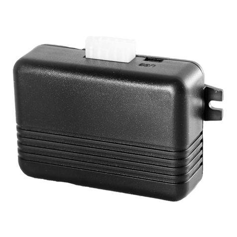
The tracker is intended for installation on a vehicle as an additional device that records the location
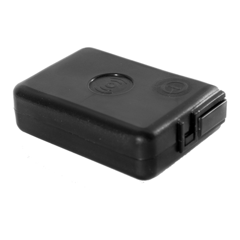
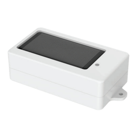
of the vehicle, its speed, and travel direction. View of the tracker is shown in Figure 1.
Additionally, the voltage level at the analog input is recorded. All events and conditions fixed by the
tracker are stored in its non-volatile memory.
The accumulated data is transmitted through the GSM 850/900/1800/1900 cellular network
operator using packet data transmission technology GPRS to a dedicated server with a static IP
address or domain name from which it can be received via the Internet for further analysis and
processing in a monitoring center.
The tracker can be configured in any convenient way: locally (via Bluetooth, using the
Configurator program) or remotely (by sending commands via SMS or GPRS).
To ensure data security, when the external power is turned off and the GSM network is lost, the
tracker has got a non-volatile memory. Data transmission is possible only if there is a GSM
850/900/1800/1900 cellular network supporting a packet data service (GPRS).
Figure 1 - View of the tracker (the wires are not shown)
The vehicle travel route is described in the form of separate points in time. The route point is
saved when at least one event occurs, such as:
−travel direction changes by an angle which is greater than the pre-set one;
−the straight-ahead travel is performed at a distance, which is longer than the pre-set one;
−the pre-set acceleration limit is broken;
−the time for putting the point while traveling (parking) is expired;
−device status change (see the Appendix A);
−an event occurs on analogue input.
In this way, route points can be saved with the time interval from one second to several
minutes allowing for a quality routing, recording any changes without a surfeit of information saved
in the “black box” and increase in GPRS traffic.

OOO Neomatica. Terminal ADM007 GLONASS / GPS. Rev.1.3 dated 13.09.2019
5
The tracker with the GLONASS/GPS module ensures time and navigation parameters
measuring based on GLONASS and/or GPS satellites. After being connected to the power supply,
the tracker starts receiving data from satellites, locating itself, identifying speed, time, measuring
voltage in inputs and connecting to the server. After being connected to the server, the tracker
transmits thereto the data packets with the pre-set frequency or when an event occurs. If for any
reason the connection to the server fails, all the information will be saved in the tracker non-volatile
memory and transmitted as soon as the connection is restored. If there is no signal from GLONASS
and/or GPS satellites and there is GPRS connection the time is synchronized via NTP protocol with
one of the available public servers. The points will be recorded without data about location.
Data transmitted by the tracker:
⎯GMT date and time;
⎯coordinates (latitude, longitude, altitude);
⎯speed, acceleration and travel direction;
⎯number of satellites when fixing a navigation problem;
⎯precision loss factor in a horizontal plane;
⎯voltage values on analogue input;
⎯data about events occurred;
⎯device status
2 Technical specifications
⎯GLONASS/GPS receiver:
chipset: МТ3333 (MediaTek);
frequency ranges: GLONASS –L1 (СT-code), GPS - L1 (С/Аcode);
sensitivity in cold start/tracking, dBm: -149 dBm/-161dBm;
number of tracking/picking-up channels: 33/99;
positioning precision, 95% of time, not worse: 3 m
⎯Connection standard:
GSM 850/900/1800/1900, GPRS Multi-slot Class 12
⎯GSM transmitter power: 2 W
⎯Number of SIM-cards: 1 or 1 SIM-chip (optional, upon request)
⎯Number of analogue inputs: 1
- Analogue input features:
voltage measurement range: 0..58,8 V

OOO Neomatica. Terminal ADM007 GLONASS / GPS. Rev.1.3 dated 13.09.2019
6
discreteness (sensitivity): 57,4 mV
input resistance: 200 kOhm
⎯Number of route records saved: at least 49 000
⎯PC connection interface: Bluetooth
⎯Operation temperature: -40..+85°С.
⎯Power voltage: +8..+45 V of unregulated direct current
⎯Current consumption (at the supply voltage 12 V):
maximum: 200 mА
average: 30 mА
⎯Dimensions: 45x25x12mm
⎯Weight: not more than 30 g.
3 Design
Functionally, the tracker consists of a microcontroller, non-volatile memory, a combined
GLONASS/GPS-, GSM-, Bluetooth module, analog input.
The GLONASS / GPS unit of the combined module is designed to receive signals from the
GLONASS / GPS satellites and determine the geographical coordinates of the receiver antenna
(latitude, longitude and altitude), as well as the exact time (GMT), speed and direction of travel.
GSM / GPRS unit of the combined module performs the following functions:
-establishment and maintenance of outgoing TCP / IP connection (data reception and transmission
in GPRS mode);
-receiving and sending SMS messages.
For information transmission, the GSM / GPRS unit of the combined module establishes and
maintains connection to the server, periodically transmitting information packets. The period of data
transfer to the server during the parking and during the movement of the vehicle is different and can
be changed by user.
Bluetooth unit of the combined module provides connection to the PC, as well as wireless
information exchange between the tracker and the configurator program ADM Configurator.

OOO Neomatica. Terminal ADM007 GLONASS / GPS. Rev.1.3 dated 13.09.2019
7
To display the operating status, the tracker has 2 LED indicators: green and blue.
The green LED indicates the status of the GLONASS / GPS unit of the combined module:
-flashes three times - the GLONASS / GPS unit is on, but there is no data from it;
-flashes twice - data from the GLONASS / GPS unit received, but the coordinates are invalid;
-flashes once - the GLONASS / GPS unit has determined the time and the actual coordinates.
The blue LED indicates the status of the GSM / GPRS unit of the combined module:
- flashes three times - the GSM / GPRS unit is disabled for re-initialization;
- flashes twice - the GSM / GPRS unit is on, but there is no connection to the server;
- flashes once - the tracker has established connection to the server and successfully transmits
information packets;
- constantly shines, briefly turning off - SIM card is not available.
Three wires are put out of the tracker: red –plus of the tracker power, black - minus, yellow -
analog input. The color marking of the tracker wires is shown in Figure 2.
Figure 2 –Color marking of the tracker wires
4 Installation
The internal GLONASS/GPS and GSM antennas are used in the tracker, which allow for its
installation almost in any place of the vehicle. However, it is not recommended to install it in the
places where the received signals will be attenuated by the vehicle metallic housing, since this can
affect the tracker work quality. For a proper function of the receiver GLONASS/GPS, put the tracker
so that its sticker is directed upwards.

OOO Neomatica. Terminal ADM007 GLONASS / GPS. Rev.1.3 dated 13.09.2019
8
Insert the SIM card into the holder with a deactivated PIN code request, activated data
transmission service via GPRS, SMS and sufficient balance for these services
Supply the power to the wires according to the layout in Figure 3: for the red wire - plus of the
vehicle network, for the black - minus of the vehicle network (housing, GND). When connecting the
plus of the vehicle network to the tracker, install a 2A fusible as close as possible to the point of
connection to the vehicle network, which is especially important when connecting directly to the
battery clamp.
Figure 3 –Standard connection layout of the tracker
If there is valid satellite data and an established connection to the server, the tracker will
determine the time, coordinates and transmitinformation packets to the server, which will be marked
by a single flashing of the green and blue LEDs.
It is highly recommended to conduct a preliminary test of the tracker's performance in the
laboratory, using a power supply instead of the vehicle network, providing an output voltage of 8 to
45 VDC and a current of at least 1A.
5 Setting the tracker
5.1 Connecting to the Configurator
To connect the ADM007 tracker to a personal computer using Bluetooth wireless technology, you
should do the following:
1) Bring the Bluetooth adapter of the PC to the working state;
2) Start the ADM Configurator program version not older than 2.2 (available for download at
http://neomatica.com);
3) Turn the Configurator to the Bluetooth radio connection mode. To do this, you need to select

OOO Neomatica. Terminal ADM007 GLONASS / GPS. Rev.1.3 dated 13.09.2019
9
the way to connect the device by clicking on the Bluetooth icon in the upper left corner of the
Configurator, as shown in Figure 4;
Figure 4 - ADM Configurator: choosing how to connect the device
4) to supply power to the tracker ADM007;
5) if there are several active trackers ADM007 within the reach of the Bluetooth adapter of the
personal computer, select the "Select device" flag and enter the last 4 digits of IMEI in
accordance with Figure 5. If there is only one active tracker ADM007 within the reach of the
Bluetooth adapter of the personal computer, you may remove the "Select device" flag. In this
case, a random tracker will be connected from all detected;
Figure 5 - ADM Configurator in device connection standby mode
6) after a few seconds the connection between the tracker and the ADMConfigurator program
will be installed and the settings window will be displayed;
7) after the device is set or, if connection of other tracker is required, click "disable device" in
the upper right corner of the ADMConfigurator program. The configurator will go into a
standby mode, as shown in Figure 6.

OOO Neomatica. Terminal ADM007 GLONASS / GPS. Rev.1.3 dated 13.09.2019
10
Figure 6 - ADM Configurator: the "disable device" button
5.2 Setting using commands
The tracker is managed by commands sent via SMS, GPRS or Bluetooth. The syntax is the
same for any way of sending.
General rules for writing and sending commands:
⎯only Latin characters and punctuation may be used in commands;
⎯character case does not matter;
⎯commands transmission syntax is the same for SMS, GPRS and Bluetooth.
⎯All commands syntax: «CMD X1,…,X3», where CMD is a command, X1..X3 are commands
parameters.
⎯Commands are separated by a SPACE. Parameters are separated by commas, except for
the DN0 command which parameters are separated by a colon.
After receiving a command, the tracker executes it and sends a feedback message.
If the command parameters extend beyond the acceptable range, the tracker changes them to
the nearest acceptable values. If it is not possible to change parameters or parameters are not
enough, the tracker will answer with an error message. A command without parameters returns the
current settings.
•Sending commands using ADM Configurator program
To configure the tracker via Bluetooth, you should use the "ADM Configurator" program. If a
password different from “0” was set in the tracker then the Configurator will ask to enter the
password.
•Sending commands using SMS messages
To manage the tracker using SMS, it is necessary to send the SMS command "ADD ME 0" to
the number of the SIM card installed in the tracker, where 0 (zero) is the default password (if the
password has been changed, you should enter it instead of 0). The phone number from which this
command was sent will be authorized in the tracker. An authorization is done only once, afterwards
the tracker saves the telephone number in a non- volatile memory within its whole service life. The

OOO Neomatica. Terminal ADM007 GLONASS / GPS. Rev.1.3 dated 13.09.2019
11
tracker can save up to 4 numbers. Resetting settings to the factory ones clears the list of phone
numbers.
•Sending commands from the server via TCP connection
To configure via GPRS, authorization is not required. The tracker receives commands from the
server via TCP connection used for data transmission.
5.3 Setting the connection to the server
Configure the APN settings for the selected cellular operators using the «SETGPRS0»
command.
Configure the IP address and port of the server (host) using the command «SETHOST0»or
"DN0".
Change of these parameters is possible in the graphical interface of the program "ADM
Configurator".
5.4 Setting data transmission
Navigation data and data received from different sensors being transmitted from the tracker to
the server, are divided by data packets. Depending on the functionality used, it is necessary to
activate the transmission of the necessary data packets.
The setting is done in the graphic interface of the ADM Configurator or by PROTOCOL
command.
Table 1 shows the correspondence of data packets to the values of PROTOCOL command. If
data transmission is required to be transmitted from several packets then calculate PROTOCOL
command parameter by addition. To save the traffic it is recommended to set only the transmission
of necessary data packets.
For example:
Main data (0) +analogue inputs (8) = PROTOCOL 8
Table 1. Values of the main parameters for PROTOCOL command
Data packet name
Parameter value
Main data
NAVIGATION DATA
0
Analogue inputs
IN_A
8

OOO Neomatica. Terminal ADM007 GLONASS / GPS. Rev.1.3 dated 13.09.2019
12
5.5. Setting route (track) drawing
5.5.1 Selecting presets of route drawing quality
To facilitate the process of setting the route drawing quality there are several factory presets.
The preset can be selected in ADM Сonfigurator (version 2.4.5 at least) or by TRACKSET
command.The presets contain several sets of parameters. In total 5 presets are available. All
presets allow to get a drawing of the travel path, the differences are in the degree of route details.
The more detailed route is the more route points will be transmitted to the server, this increases the
traffic consumption. Less detailed route reduces traffic consumption.
• TRACKSET command description:
TRACKSET X
X –number of route drawing preset
X = 0..4
In response a total list of set parameters will be displayed.
Answer example: TRACK 4,1000,100; (1):3,5; (2):3,5; (3):3,5
Command without parameters displays current route settings.
• Presets description:
TRACKSET 0
Satisfactory tracking quality, money-saving variant as regards route points and traffic
consumption. The quality is enough to monitor the movement path. The drawing of road turns is
simplified. Slight route changes are not drawn (expected points per km are twice less than in preset
2).
TRACKSET 1
A good tracking quality. The drawing of slight changes of direction and road turns is simplified
(expected points per km are 1.3 times less than in preset 2)
TRACKSET 2
Set by default. A good tracking quality. The variant suits to the most of tasks. Is an average
variant as regards tracking drawing quality and traffic consumption. Slight direction changes and
road turns are drawn with details.
TRACKSET 3
Slight changes in direction are drawn with more details (expected points per km are 1.3 times
more than in preset 2)

OOO Neomatica. Terminal ADM007 GLONASS / GPS. Rev.1.3 dated 13.09.2019
13
TRACKSET 4
High tracking detalization. Slight changes in direction are drawn with many details. (expected
points per km are 1.6 times more than in preset 2)
5.5.2 Expert setting of tracking parameters.
It is recommended to use this method of setting only if none of the presets fit the task. The
change of these parameters can lead to an increase of traffic consumption or to a decrease of the
route drawing quality.
• Setting using TRACK command
To set all the parameters send TRACK command twice. The degree of road turns detalization
is set by sending TRACK command with three parameters. Command format: TRACK M,A,B
The threshold values of additional circumstances of route points drawing in movement are set
by sending TRACK command with four parameters. Command format: TRACK 255,X,Y,Z
• Setting the degree of road turns drawing detalization. Setting threshold values of angle
change and deflection.
A route point is drawn when the thresholds are exceeded.
TRACK M,A,B
M –number of speed mode.
M=255 –apply the same parameters for all the modes
M=0 –slow movement
M=1 –medium -speed movement
M=2 –fast movement
A –angle for speed mode with M number.
B –deflection for speed mode with M number.
The threshold values of angle change and deflections are set separately for three speed
modes. If the same values should be set for all speed modes then the command should be sent
once, M parameter in this case equals to 255. If different threshold values should be set for three
speed modes then the command should be sent 3 times, choose speed mode using M parameter.
Example
• Setting same parameters for all speed modes:
TRACK 255,10,6 –Set 10 degrees for the threshold value of route change and 6 for deflection
• Setting different parameters for all speed modes:

OOO Neomatica. Terminal ADM007 GLONASS / GPS. Rev.1.3 dated 13.09.2019
14
TRACK 0,20,7 –Set 20 degrees for the threshold value of route change and 7 for deflection
of slow speed mode.
TRACK 1,10,6 –Set 10 degrees for the threshold value of route change and 6 for deflection
of medium speed mode.
TRACK 2,5,6 –Set 5 degrees for the threshold value of route change and 6 for deflection of
fast speed mode.
• Setting minimum speed, distance and acceleration.
If the set threshold values are exceeded, a route point will be recorded.
TRACK 255, X,Y,Z –
First parameter should always be equal to 255. For all speed modes these parameters are set
the same.
X –minimum speed
Y –distance (meters)
Z –acceleration (km/h per second)
• Viewing set parameters
TRACK –Display current settings.
The response displays minimum speed, distance, acceleration, angle and deflection for three
speed modes.
Response format:
TRACK X,Y,Z; (M) A1,B1; (M) A2,B2; (M) A3,B3
X –minimum speed
Y - distance (meters)
Z - acceleration (km/h per a second)
M=0 –slow movement
M=1 –medium speed movement
M=2 –fast movement
A –angle for speed mode with M number
B –deflection for speed mode with M number
Answer example: TRACK 4, 1000, 15; (0):5,6; (1):10,6; (2):20,6

OOO Neomatica. Terminal ADM007 GLONASS / GPS. Rev.1.3 dated 13.09.2019
15
5.6 Setting the fixation (freezing) of coordinates during the parking
The margin of error might cause a slight coordinates dispersion during a long-term parking of
the vehicle. To prevent this effect the coordinates freezing function can be used in the beginning of
the parking. This mode is activated automatically when the discrete level is changed at the analog
input, or at a speed below the set level. Simultaneous use of both ways of coordinates fixation is
impossible. The tracker records the coordinates in the mode that was last configured.
5.6.1 Coordinates fixation by the ignition
To activate the function of fixing the coordinates with the vehicle ignition off, it is necessary
to connect to the analog input a circuit being under voltage when the ignition is on. Activate adiscrete
mode for this analogue input and set the values range of voltage level for the logical one as
"INTRUE" and for the logical zero as "INFALSE". Afterwards select coordinates fixation mode “by
the ignition”. Thus, when the ignition is off, coordinates fixation will be initiated by an event formed
at the input.
•Examples of using INSTATIC command:
Coordinates fixation at 0 in the input AIN0 INSTATIC 0,0
The function is disabled by the command «INSTATIC 255».
5.6.2 Coordinates fixation by speed
In such a mode the coordinates fixation is done automatically if the tracker registers the speed
beyond the set threshold. The precision of this function depends on the precision of the coordinates
determination. Thus, in case of bad signal receipt from GLONASS/GPS satellites, the coordinates
fixation by the speed might be not stable.
The function of fixing coordinates by speed is activated by the command «SPEEDSTATIC
X», X is the speed (km / h), below which the coordinates are fixed. The function is disabled by the
«SPEEDSTATIC 255» command.
SPEEDSTATIC 3 is set by default.
Selecting rather high-speed threshold may result in improvement of function performance
during parking, but may cause data loss when driving at the beginning or when driving at a low
speed. 5.7 Operation mode
The tracker has got two modes of routes record: «Tracker» and «Beacon». The working mode is
set by BMODE command. Mode “Tracker” is set by default.

OOO Neomatica. Terminal ADM007 GLONASS / GPS. Rev.1.3 dated 13.09.2019
16
BMODE X
X=0 -«Тracker» mode.
X=1 - «Beacon» mode.
5.7.1 “Tracker” operation mode
This mode is used to create (draw) exact path of travel.
The routes record is done using all possible criteria:
⎯change of speed;
⎯acceleration threshold exceeding;
⎯distance passage;
⎯direction change;
⎯regarding the period of movement;
⎯regarding the period of parking;
⎯regarding alarm period;
⎯at tracker start up;
⎯change of discrete state at input;
⎯change of device status
5.7.2 “Beacon” operation mode
This mode is used to record routes at a given time period and is not suitable for the creation of
exact path of travel. Time period of routes record equals to the period of routes record while parking.
The routes record is done only using the following criteria:
⎯at tracker start up;
⎯change of discrete state at input;
⎯regarding the parking period;
⎯regarding alarm period;
⎯change of device status
6 Connection of additional equipment
The analog input IN0 (AIN0) can be used to connect analog type sensors and voltage level
measurement, and can also be interpreted as discrete.
Voltage measurement range: 0..58.8 V.
Discreteness (sensitivity): 57.4 mV.
Minimum input resistance: 200 kOhm.
Do not apply voltage exceeding the upper limit of the measuring range.

OOO Neomatica. Terminal ADM007 GLONASS / GPS. Rev.1.3 dated 13.09.2019
17
If it is necessary to record a certain voltage level, for example, in the ignition switching circuit,
the voltage levels of the logical "0" with the "INFALSE" command and the logical "1" with the
"INTRUE" command must be set for the selected analog input.
Description of the commands:
INFALSE IN, X0, Y0
IN - number of the analog input (always specify 0)
X0 - the lower limit of the logical range "0" (fixed value 0mV)
Y0 - upper limit of the logical range "0" (variable value)
INTRUE IN, X1, Y1
IN - number of the analog input (always specify 0)
X1 - the lower limit of the logical range "1" (variable value)
Y1 - the upper limit of the logical range "1" (fixed value of 60000 mV)
When entering these commands, the voltage must be specified in millivolts.
Figure 7 - Bands of discrete states
If the voltage level is in the zone of indifference, the previous discrete state is maintained until
the level goes beyond the zone of indifference.
The measured voltage levels are registered by the tracker and transmitted to the server.
When changing the discrete state, an extraordinary packet is sent.

OOO Neomatica. Terminal ADM007 GLONASS / GPS. Rev.1.3 dated 13.09.2019
18
7 Description of commands
Table 1. Description of commands
Command
Answer
Parameters
Description
1
Name X
Example:
Name bus8
Device Name ‘X‘
Example:
Device Name ‘bus8‘
X –tracker name
Set the name of the tracker. The name can contain only
letters of the Latin alphabet and numbers. The name
cannot exceed 10 characters in length. The tracker
name is added to the alarm SMS messages.
2.1
ADD ME X,Y (only by
SMS)
Example:
ADD ME 1234
ADD ME 1234,2
PHONES (0)= (1)= (2)=(3)=
Example:
PHONES(0)=+7xxxxxxxxxx
(1)= (2)= (3)=PHONES
(0)=(1)= (2)=
+7xxxxxxxxxx (3)=
X –password, the default
is "0".
Y=0..3 –number of the
memory location to store
the number. Optional
parameter.
Authorize the phone number from which the SMS was
received and write it to the memory cell Y. The
command is needed only to create a list of numbers for
controlling the tracker via SMS.
2.2
ADD ME X,Y (only by
Bluetooth and GPRS)
Example:
ADD ME +7xxxxxxxxxx,1
PHOES (0)= (1)= (2)= (3)=
Example:
PHOES (0)= (1)=
+7xxxxxxxxxx (2)= (3)=
X –phone number
Y=0…3 – number of the
memory location for
storing the number
Adding a phone number from which you plan to manage
the tracker via SMS.
3
PHONES X
Example:
PHONES 1234
PHOES (0)= (1)= (2)(3)=
Example:PHONES (0)=(1)=
+7xxxxxxxxxx (2)= (3)=
X –password, default is
"0".
Request a list of authorized phone numbers.
4
PASS X,Y
Example:
PASS 0,86974543
Pass=X,Y
Example:
Pass=86974543
X –old password, default
X=0. Y –New password.
Change the password from the old X to the new Y.
The password is a numberfrom one to eight characters.
5
STATUS
Example:
ID=1 Soft=0x1A GPS=9291
Time=11:21:39 25.02.10
Nav=0 Lat=57.2359
Lon=56.2593 Speed=0.0
SatCnt=5 Stat=0x0000
Command without
parameters.
Query the current state of the tracker.
ID - the number of the tracker, Soft - the software
version, GPS - the current number of the information
packet, Time - current time and date according to
Greenwich Mean Time
Nav - reliability of coordinates,
Lat is the latitude,
Lon - longitude,
Speed - speed,
SatCnt - the number of satellites,
Stat - status.
6
IMEI
Example:
IMEI
IMEI
Example:
IMEI 359587013832624
Command without
parameters.
Request IMEI GSM-module installed in the tracker. The
command runs 20 seconds after the tracker is switched
on or restarted.
7
SN X
Example:
SN 123456789
SN X
Example:
SN 123456789
X –settable tracker ID
Set the tracker ID.
8
PIN0 X
Example:
PIN0 1234
PIN0 X
Example:
PIN0 1234
X –pin code sim card
Set the PIN code of the SIM card.
9
SETGPRS0 X,Y,Z
Example:
SETGPRS0
internet.mts.ru,mts,mts
GPRS0: APN=X, user=Y,
pass=Z
Example:
X –access point, default
X=internet.beeline.ru;
Y - login, default
Y=beeline;
Set APN settings for the SIM card. A command without
parameters returns the current GPRS settings for the
SIM card.

OOO Neomatica. Terminal ADM007 GLONASS / GPS. Rev.1.3 dated 13.09.2019
19
GPRS:
APN=internet.mts.ru,
user=mts, pass=mts
Z –password, default
Z=beeline.
10
SETHOST0 X,Y
Example:
SETHOST0
134,236,21,2,12300
HOST0=X,Y
Example:
HOST0=134.236.21.2:1230
0
X - IP adress,
Y - server port.
Five numbers separated
by commas.
Configuring the IP address and port of the server to
which the tracker connects to transmit information. A
command without parameters returns thecurrent server
address and port.
11
DN0 X:Y
Example:
DN0 www.test.ru:1000
HOST0=X:Y
Example:
HOST0= www.test.ru:1000
X - domain name of the
server,
Y - server port.
Configure the domain name and port of the server to
which the tracker connects to transmit information. A
command without parameters returns thecurrent server
address and port.
12
ERASE FLASH
ERASE FLASH
Command without
parameters.
Erase all information packets stored in memory. After
executing this command, the current information packet
number is reset, the tracker is rebooted.
13
ERASE EEPROM
ERASE EEPROM
Command without
parameters.
Restore the tracker's factory settings and restart the
tracker.
14
PERIOD X,Y
Example:
PERIOD 20,120
PERIOD min=X, max=Y
Example:
PERIOD min=20, max=120
X –the recording period
during the movement in
seconds,default X=30.
Y –the recording period
during parking in
seconds, by default
Y=300.The value of X
must be less than Y.
Set the recording period in the memory of information
packets during driving and parking.
A command without parameters returns the current
settings.
15
TRACKSET X
The response displays
a detailed
configuration of all set
parameters of the
travel path
X= 0…4
Select the preset of the travel path drawing
quality. More details see in clause 5.5.1
Selecting presets of route drawing quality
16
InTrue X,Ymin,Ymax
Example:
InTrue 0,10000,60000
InTrue X,Ymin,Ymax
Example:
InTrue 0,10000,60000
X=0 –input number
(always 0);
Ymin –minimum range
limit in mV;
Ymax=60000 –the
maximum range limit in
mV (unchanged value).
Set the voltage range of the logical unit on the analog
input.
17
InFalse X,Ymin,Ymax
Example:
InFalse 0,0,4000
InFalse X,Ymin,Ymax
Example:
InFalse 0,0,4000
X=0 –input number
(always 0). Ymin –
minimum range limit in
mV; Ymax –maximum
range limit in mV.
Set the voltage range of logical zero on the analog input.
18
InInfo X
Example:
InInfo 0
Example: Input 0: InTrue
8000..15000, InFalse
0..3000
X=0 –input number
(always 0).
Request information about the input settings.
19
INPUT
INPUT0 = 12000
Command without
parameters.
Query the current measured voltage level at the analog
input (mV).

OOO Neomatica. Terminal ADM007 GLONASS / GPS. Rev.1.3 dated 13.09.2019
20
20
INSTATIC X,Y
Example:
INSTATIC 1,0
INSTATIC X,Y
Example:
INSTATIC 1,0
X=0 –input number,
Y=0, 1 –inclusion by zero
or one.
X=255 –disabled function;
Set the input number to enable the fixation mode. A
command without parameters returns the current
setting. By default, no one input is set to enable the
fixation mode.
21
SPEEDSTATIC X
Example:
SPEEDSTATIC 2
SPEEDSTATIC X
Example:
SPEEDSTATIC 2
X –the speed below
which the fixation of
coordinates takes place.
X=255 –disabled function
Set the speed which reducing will initiate coordinates
freezing.
22
RESET
reset…
Command without
parameters.
Reboot the device.
23
UPDATE
Command without
parameters.
Firmware upgrade.
8 Upgrading tracker software
The tracker software (firmware) can be updated via the Bluetooth radio channel using a
configurator program or via a GPRS channel.
8.1 Updating the tracker software via the configurator
The configurator program, if the computer has access to the Internet, checks the current
firmware version on the update server, and, if necessary, downloads the firmware file.
To update the firmware, do the following:
1. establish connection between the ADM007 tracker and the ADM Configurator program using
the procedure described in 5.1 "Connecting to the Configurator";
2. if ADM Configurator detects the firmware that is more updated than the one installed in the
tracker then it will inform about this - the notification will be displayed in the lower left corner;
3. click "Update available";
4. In the opened "Notifications" tab, click "Update";
5. after the update, the tracker will reboot and become available for configuration.
ATTENTION! Do not switch off the tracker during the firmware upgrade process until the tracker is
detected by the setup program. Otherwise, it is possible to damage the software, which must be
restored in the service center of the manufacturer
8.2 Updating the tracker software via the configurator using the firmware
file
The firmware file must be requested from the technical support.
To update the firmware via Bluetooth using the firmware file, do the following:
1. establish a connection between the ADM007 tracker and the ADM Configurator program using
Table of contents
Other Neomatica GPS manuals
