Neosens Skidsens User manual

1
Manual
SKIDSENS
Fouling Sensor
by Neosens
Quick User Manual
Installation Guide
Advantage Controls
P.O. Box 1472
Muskogee, OK 74402
Phone: 800-743-7431
Fax: 888-686-6212
www.advantagecontrols.com
email: [email protected]
3/2011

2
Specifications
Electrical:
• Input: 36 VDC @ 60mA
• Output: 4-20mA(500Ω)
Environment:
• Ambient temperature - 0 to 180oF
(withoutPVCadapter)
• Relative humidity - 0 to 100%
• Pressure - 80 PSI Max
Fouling Monitoring: 0-1mm(0to0.039in)
Accuracy: 1% of Full scale
Material: PVC(body)&316LSS(sensortip)
Connection: •Sensorsaresuppliedwitha1”(2.54cm)slipanda1”MNPTPVCquick
releaseadaptor.ThePVCadaptorhasamaximumtemperaturerating
of 125oF.
•Peaksensorbodyhas1/2”straightBMPT
Shipping Weight: 4lbs(1.814kg)
Sensor Length: 9.375”(23.8cm)
Insertion Depth: Approx.3.375”(8.57cm)

3
Installation Notes
1. Install the sensor into flowing water for 30 minutes to allow the sensor to reach a temperature
equilibrium.
2. Sensor must have a minimum of 3.5 gpm flow across it.
3. Theanalogoutputisactiveandreferencedto+36Vdc.
4. If connected to a monitor with other 4-20mA inputs, they must be isolated from each other or this
input.ContactAdvantageControlsifaloopisolatorisrequired.
5. After the sensor has been installed and powered for 2 hours confirm that the output is a 4mA
signal.
Testing Sensor
If the sensor is giving a 3mA output after being installed for at least 2 hours in the minimum flow rate
of 3.5 gpm the following steps can be followed to test and reset the sensor’s operation.
1. Power OFF the Skidsens
2. AssumingtheSkidsenswasmaintainedinwaterwiththerequiredflowrate(>3.5gpm),powerON
the Skidsens and check the analog output reading during the first 20 seconds, as the probe will
be in test mode
a. For the first 10 seconds, the probe should display a 4mA signal
b. For the next 10 seconds, the probe should display a 20mA signal
3. After those initial 20 seconds, the probe will go to operational mode and should return to a 4mA
signal, or slightly above assuming the sensor has no fouling.

4
+--
4-20mA Probe Out
Sensor Input
RED
BLUE
WHITE
BROWN
GREEN (GND)
GREEN (GND)
+--
+--
36 VDC Signal
BLACK (HOT)
WHITE (NEU)
Power
SKIDSENS
Probe
Power Cord
J2-8
J2-1
J1-8
J1-1
4-20mA Input 1-
4-20mA Input 1+
4-20mA Input 2-
4-20mA Input 2+
4-20mA Input 3-
4-20mA Input 3+
4-20mA Input 4-
4-20mA Input 4+
4-20mA Input 5-
4-20mA Input 5+
4-20mA Input 6-
4-20mA Input 6+
LED
4-20mA Input Card
Note: The number of
channels or 4-20mA
inputs depends on
on the number ordered.
4-20mA Input 7+
4-20mA Input 7-
4-20mA Input 8+
4-20mA Input 8-
Wiring Diagram for MegaTron Connection
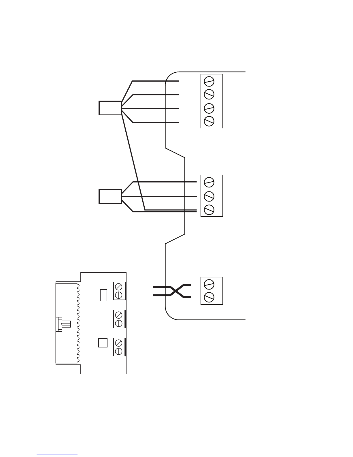
5
+--
4-20mA Probe OutPower
Sensor Input
RED
BLUE
WHITE
BROWN
GREEN (GND)
GREEN (GND)
+--
+--
36 VDC Signal
BLACK (HOT)
WHITE (NEU)
SKIDSENS
Probe
Power Cord
Input 1 -
Input 1 +
Input 2 -
Input 2 +
MegaTron SS
4-20mA Input
Rev D
Part # SS-MAI-2
Input 3 -
Input 3 +
Wiring Diagram for MegaTron SS Connection

6
Step 1:
First, push the SET UP RUN button to get this
screen. From here push the CUSTOMIZE (Button
4)togotothenextscreen.
>HOME SETUP<
SETPOINTS DATE/TIME
CALIBRATION CONFIGURE
TIMERS HISTORY
CUSTOMIZE WATER METER
ALARMS RELAYS
Step 2:
This is the Customize Screen. From here push
the mA IN(Button9)togotothenextscreen.
>CUSTOMIZE<
UNIT NAME
RELAY NAMES NOTEPAD
SYS NAME
INPUT NAMES mA IN
RUN SCREEN
Step 3:
This is the mA IN screen. From here push
INPUT 1 OR 2(Button1or2)thengotothenext
screen.
>CUSTOMIZE mA INPUTS<
INPUT 1
INPUT 2
Step 4:
ThisistheCustomizemAInput1Screen.From
here push the NAME(Button1)togotothenext
screen.
>CUSTOMIZE mA INPUT 1<
NAME FOULING
UNITS mm
NUMBER x.xxx
Step 5:
ThisistheCustomizemANamescreen.Fromhere
enterthenameofthemAInput(i.e.FOULING)
byusingtheArrowbuttons.ThenpressENTER
to confirm and return to the previous screen.
>CUSTOMIZE mA INPUT 1<
NAME FOULING
UNITS mm
NUMBER x.xxx
Step 6:
From here push the UNITS(Button 2) togotothenext
screen.
>CUSTOMIZE mA INPUT 1<
NAME FOULING
UNITS mm
NUMBER x.xxx
Step 7:
ThisistheCustomizemAUnitsscreen.Fromhereselect
the type of units (i.e. mm) by using the Arrow buttons.
ThenpressENTER to confirm and return to the previous
screen.
>CUSTOMIZE mA INPUT 1<
NAME FOULING
UNITS mm
NUMBER x.xxx
Step 8:
From here push the NUMBER(Button3)togotothenext
screen.
>CUSTOMIZE mA INPUT 1<
NAME FOULING
UNITS mm
NUMBER x.xxx
Step 9:
ThisistheCustomizemANumberFormatscreen.From
here select the number format (i.e. x.xxx) by using the
Arrowbuttons.ThenpressENTER to confirm and HOME
to return to the Home screen.
>CUSTOMIZE mA INPUT 1<
NAME FOULING
UNITS mm
NUMBER x.xxx
mA INPUT 1 NAME
[FOULING ]
USE ARROW KEYS TO CHANGE, PRESS
ENTER TO ACCEPT OR BACK TO ERASE
MegaTron Menus • Customize Setup
TYPE OF UNITS
-> mm
USE UP/DOWN KEYS TO CHANGE
PRESS ENTER TO ACCEPT
NUMBER FORMAT
-> X.XXX
USE UP/DOWN KEYS TO CHANGE
PRESS ENTER TO ACCEPT

7
Step 1:
First, push the SET UP RUN button to get this
screen. From here push the CALIBRATION
(Button2)togotothenextscreen.
>HOME SETUP<
SETPOINTS DATE/TIME
CALIBRATION CONFIGURE
TIMERS HISTORY
CUSTOMIZE WATER METER
ALARMS RELAYS
Step 2:
This is the Calibration Screen. From here push
the mA IN(Button7)togotothenextscreen.
>CALIBRATION<
SENSORS mA OUT
mA IN
Step 3:
ThisistheCurrenLoopCalibrationscreen.From
here push INPUT 1 OR 2(Button1or2)thengo
to the next screen.
>CURRENT LOOP CALIBRATION<
INPUT 1
INPUT 2
Step 4:
This is the mA Input Calibration Screen. From
here choose the MAX or MIN(Button3and4)to
go to the next screen.
>mA INPUT CALIBRATION<
20 mA 19649
4 mA 3913
MAX 1.000 mm
MIN 0.000 mm
OFFSET Enabled
Step 5:
ThisisthemAInputMAXscreen.Fromhereadjustthe
MAXreadingbyusingthenumberkeys(MAXshouldbe
set to 1.000 mm and MIN should be set to 0.000 mm).
ThenpressENTER to confirm and return to the previous
screen.
Note: All other mA Input Calibration settings can be
adjustedinthesamefashionbeginningatStep4.
>mA INPUT CALIBRATION<
20 mA 19649
4 mA 3913
MAX 1.000 mm
MIN 0.000 mm
OFFSET Enabled
mA INPUT 1 MAX (1.000 mm)
[_. ] mm
USE NUMBER KEYS TO CHANGE, PRESS
ENTER TO ACCEPT OR BACK TO ERASE
MegaTron Menus • Calibration Setup

8
Get the Advantage in Water Treatment Equipment
Advantage Controls can give you the Advantage in products, knowledge
and supportonallofyourwatertreatmentequipmentneeds.
CoolingTowerControllers
Boiler Blow Down Controllers
Blow Down Valve Packages
Solenoid Valves
Water Meters
Chemical Metering Pumps
Corrosion Coupon Racks
ChemicalSolutionTanks
Solid Feed Systems
FeedTimers
FilterEquipment
GlycolFeedSystems
Pre Fabricated Systems
Get the Advantage
Table of contents
Popular Accessories manuals by other brands

Reliable Controls
Reliable Controls SS-L-BL-CO2-H user guide

Marport
Marport Seine Service manual

Technische Alternative
Technische Alternative RAS PLUS DL Operation, Programming, Installation Instructions

Orion
Orion 90mm f/10.1 refractor Instruction manuals

aci
aci TUCH2 Installation & operation instructions

V-TAC
V-TAC VT-10005 instruction manual

Intelbras
Intelbras IVP 7001 MW EX user manual

Aroma Outfitters
Aroma Outfitters 3D Glass manual

Bisque
Bisque TheSky Fusion quick start guide

LEGRAND
LEGRAND Wattstopper DSW-301-R installation instructions

Solid State Logic
Solid State Logic MadiXtreme. Hi-speed MADI I/O reference guide

Asus
Asus ROG RYUO III ARGB Series quick start guide