Neousys Technology PCIe-USB380/340 User manual

Neousys Technology Inc.
PCIe-USB380/ 340 Card
Frame Grabber Card
User Manual
Rev. A1.1

Table of Contents
Table of Contents
Table of Contents...................................................................................................................2
Legal Information...................................................................................................................3
Contact Information...............................................................................................................4
Notices....................................................................................................................................5
Safety Precautions.................................................................................................................6
Service and Maintenance ......................................................................................................7
ESD Precautions....................................................................................................................7
About This Manual.................................................................................................................8
1Introduction
1.1 Product Specification...............................................................................................10
2Setting Up Your PCIe-USB Card
2.1 Unpacking Your PCIe-USB Card .............................................................................11
2.2 Superior View............................................................................................................11
2.3 Jumper Pin Settings.................................................................................................12
2.3.1 Jumper Pin Location.........................................................................................12
2.3.2 Jumper Pin Setting Example.............................................................................12
2.4 DIP Switch Settings..................................................................................................13
2.4.1 The DIP Switch .................................................................................................13
2.4.2 Board ID Settings..............................................................................................14
3PCIe-USB Card Installation
3.1 Hardware Installation...............................................................................................15
3.2 Software Installation ................................................................................................17

Legal Information
Legal Information
All Neousys Technology Inc. products shall be subject to the latest Standard Warranty
Policy.
Neousys Technology Inc. may modify, update or upgrade the software, firmware or any
accompanying user documentation without any prior notice. Neousys Technology Inc. will
provide access to these new software, firmware or documentation releases from
download sections of our website or through our service partners.
Before installing any software, applications or components provided by a third party,
customer should ensure that they are compatible and interoperable with Neousys
Technology Inc. product by checking in advance with Neousys Technology Inc.. Customer
is solely responsible for ensuring the compatibility and interoperability of the third party’s
products. Customer is further solely responsible for ensuring its systems, software, and
data are adequately backed up as a precaution against possible failures, alternation, or
loss.
For questions in regards to hardware/ software compatibility, customers should contact
Neousys Technology Inc. sales representative or technical support.
To the extent permitted by applicable laws, Neousys Technology Inc. shall NOT be
responsible for any interoperability or compatibility issues that may arise when (1)
products, software, or options not certified and supported; (2) configurations not certified
and supported are used; (3) parts intended for one system is installed in another system
of different make or model.

Contact Information
Contact Information
Headquarters
(Taipei, Taiwan)
Neousys Technology Inc.
15F, No.868-3, Zhongzheng Rd., Zhonghe Dist., New Taipei City, 23586, Taiwan
Tel: +886-2-2223-6182 Fax: +886-2-2223-6183 Email, Website
Americas
(Illinois, USA)
Neousys Technology America Inc.
3384 Commercial Avenue, Northbrook, IL 60062, USA
Tel: +1-847-656-3298 Email, Website
China Neousys Technology (China) Ltd.
Room 612, Building 32, Guiping Road 680, Shanghai
Tel: +86-2161155366 Email, Website

Notices
Notices
Copyright All rights reserved. This publication may not be
reproduced, transmitted,
transcribed, stored in a retrieval system, or translated into any language or
computer language, in any form or by any means, electronic, mechanical,
magnetic, optical, chemical, manual or otherwise, without the prior written
consent of Neousys Technology, Inc.
Disclaimer This manual is intended to be used as an informative guide only and is subject
to change without prior notice. It does not represent commitment from Neousys
Technology Inc. Neousys Technology Inc. shall not be liable for any direct,
indirect, special, incidental, or consequential damages arising from the use of
the product or documentation, nor for any infringement on third party rights.
Patents and
Trademarks
Neousys, the Neousys logo, Expansion Cassette, MezIOTM
are registered
patents and trademarks of Neousys Technology, Inc.
Windows is a registered trademark of Microsoft Corporation.
Intel®, Core™ are registered trademarks of Intel Corporation
NVIDIA®, GeForce®are registered trademarks of NVIDIA Corporation
All other names, brands, products or services are trademarks or registered
trademarks of their respective owners.
FCC
Conformity
This equipment has been tested and found to comply with the limits for a Class A
digital device, pursuant to part 15 of the FCC Rules. These limits are designed to
provide reasonable protection against harmful interference when the equipment is
operated in a commercial environment. This equipment generates, uses, and can
radiate radio frequency energy and, if not installed and used in accordance with the
instruction manual, may cause harmful interference to radio communications.
Operation of this equipment in a residential area is likely to cause harmful
interference in which case the user will be required to correct the interference at his
own expense.
CE Conformity The product(s) described in this manual complies with all applicable European
Union (CE) directives if it has a CE marking. For computer systems to remain CE
compliant, only CE-compliant parts may be used. Maintaining CE compliance also
requires proper cable and cabling techniques.

Safety Precautions
Safety Precautions
Read these instructions carefully before you install, operate, or transport the system.
Install the system or DIN rail associated with, at a sturdy location
Install the power socket outlet near the system where it is easily accessible
Secure each system module(s) using its retaining screws
Place power cords and other connection cables away from foot traffic.
Do not place items over power cords and make sure they do not rest
against data cables
Shutdown, disconnect all cables from the system and ground yourself
before touching internal modules
Ensure that the correct power range is being used before powering the
device
Should a module fail, arrange for a replacement as soon as possible to
minimize down-time
If the system is not going to be used for a long time, disconnect it from
mains (power socket) to avoid transient over-voltage

Service and Maintenance/ ESD Precautions
Service and Maintenance
ONLY qualified personnel should service the system
Shutdown the system, disconnect the power cord and all other connections
before servicing the system
When replacing/ installing additional components (expansion card, memory
module, etc.), insert them as gently as possible while assuring proper
connector engagement
ESD Precautions
Handle add-on module, motherboard by their retention screws or the
module’s frame/ heat sink.
Avoid touching the PCB circuit board or add-on module connector pins
Use a grounded wrist strap and an anti-static work pad to discharge static
electricity when installing or maintaining the system
Avoid dust, debris, carpets, plastic, vinyl and styrofoam in your work area.
Do not remove any module or component from its anti-static bag before
installation

About This Manual
About This Manual
This manual introduces and describes how to setup/ install Neousys Technology PCIe-USB380/ 340,
they are USB3.0 host adaptor cards that offer expandability, stability and SuperSpeed USB3.0
performance to your existing system.
Revision History
Version Date Description
A1 Aug. 2013 Initial release
A1.1 Apr. 2019 Updated jumper settings
Updated DIP switch settings

PCIe-USB380/ 340 Card
1 Introduction
Neousys PCIe-USB380/340 is an 8/4-port USB 3.0 host adapter dedicatedly designed for industrial and
vision applications. USB 3.0, or SuperSpeed USB, is an emerging bus technology to deliver ten times of
data rate over USB 2.0, and is particularly useful for high-speed data storage and image devices.
Most off-the-shelf USB 3.0 cards implement multiple ports with a single USB 3.0 controller that may
result in significant performance degradation for multi-port operation. To achieve maximal per-port
performance, PCIe-USB380/340 has four independent NEC/ Renesas μPD720202 USB 3.0 Host
Controllers and x4 PCI Express® Gen2 interface to offer up to 5Gbps of bandwidth for each port even
when all ports are plugged in and accessed simultaneously. In addition to the bandwidth advantage,
Neousys PCIe-USB card features on-board regulated 5 VDC power supply with user-configurable
900mA/ 1500mA current limit design to supply stable 5 VDC power to external USB devices. It also
supports software-programmable per-port power on/off control for fault recovery operations.
Combining high bandwidth, industrial-grade power design and reliable cable connection, Neousys
PCIe-USB Card brings expandability, stability and ultra-fast USB 3.0 performance to existing
systems.

PCIe-USB380/ 340 Card
1.1 Product Specification
Specifications
Bus interface 4-lanes, Gen2 PCI Express interface
Compliant with PCI Express Base Specification Revision 2.0
USB ports USB380: 8x USB 3.0 ports, compatible with USB 2.0/ 1.1/ 1.0
USB340: 4x USB 3.0 ports, compatible with USB 2.0/ 1.1/ 1.0
USB controller
4x NEC/ Renesas μPD720202 Host Controllers
Compliant with Universal Serial Bus 3.0 specification Revision 1.0
Compliant with Intel® xHCI specification Revision 1.0
USB connectors 4x on-panel USB 3.0 Type-A connectors with M2 screw threads
4x on-board USB 3.0 Type-Aconnectors with fix points for cable tie
USB current limit User-configurable 900mA/ 1500mA per-port current limit
Power requirement Maximal 2.0A @ 3.3V from PCI Express bus
Maximal 5.5A @ 12V from directly PCI Express bus for USB devices
Operating temperature 0 ~ 60 C with ambient air flow
Dimension 167.7 m (W) x 111.2 mm (H)
Compatible operating
systems
Windows XP
Windows Vista 32Bit
Windows Vista 64bit
Window 7 32bit
Windows 7 64bit
Windows 8
Windows 8.1
Windows 10

PCIe-USB380/ 340 Card
2 Setting Up Your PCIe-USB Card
2.1 Unpacking Your PCIe-USB Card
Upon receiving the PCIe-USB card package, please check immediately if the package contains all
the items listed in the following table. If any item is missing or damaged, please contact your local
dealer or Neousys Technology Inc.
Item Description Qty
1 PCIe-USB card (USB380 or USB340) 1
2 Drivers & Utilities Disc 1
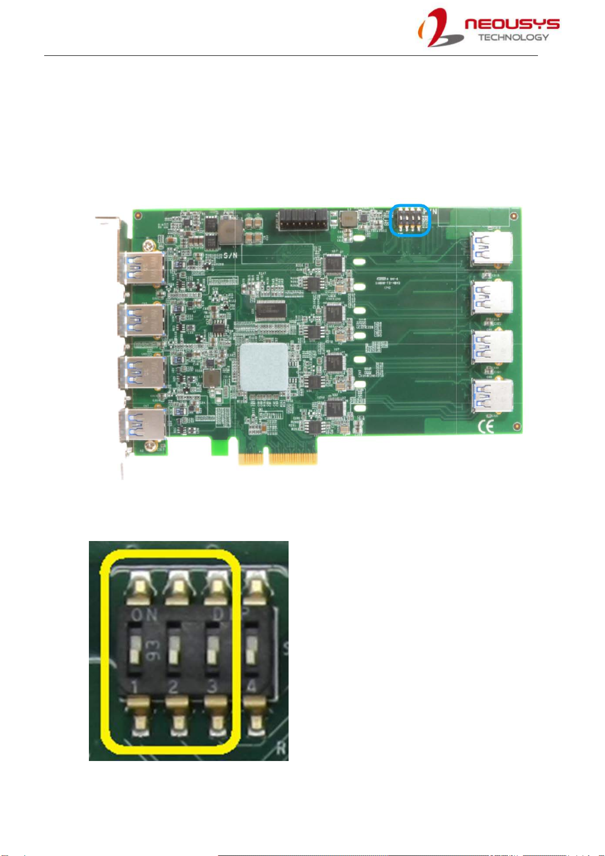
2.2 Superior View
Shown below is a PCIe-USB380 card, the four channels exposed on the external panel are
channels 1/ 3/ 5/ 7 while the internal channels are 0/ 2/ 4/ 6. On the top, there are a set of jumper
pins (indicated in red), they offer per-port current configurable settings of 900mA or 1500mA.
Please refer to the jumper pin settings for details. Also at the top, there are a set of DIP switches
(indicated in blue), they offer PCIe-USB card ID settings for when you install multiple cards in your
system, the ID can help you identify each PCIe-USB card.
NOTE
For PCIe-USB340, there are only channels 1/ 3/ 5/ 7 connectors and corresponding jumpers.

PCIe-USB380/ 340 Card
2.3 Jumper Pin Settings
The current output setting can be configured for each individual USB port. The current output can
be set at 900mA (JP2/ 3 connected) or 1500mA (JP1/ 2 connected). If the jumper pins are not set,
the default output current will be 900mA. You may also set all channels to output 1500mA without
any issue. Please refer to the following illustration and description for details.
2.3.1 Jumper Pin Location
The jumper pin location is indicated in red.
2.3.2 Jumper Pin Setting Example
Channel1 is set for 1500mA output
Channel6 is set for 900mA output
Channels 1/ 2/ 3/ 4/ 5/ 6have no jumper connection thus are offering 900mA output.
PCIe-USB380/ 340 Card
2.4 DIP Switch Settings
PCIe-USB cards feature per-port power on/off control via Neousys’ API so you may manually cut off
or resume the power delivery to the connected device. This feature is designed for failure recovery
in the field to rest connected devices. To support per-port on/off control for multiple cards, PCIe-
USB cards have a set of DIP switches (indicated in blue) to configure user-defined board ID. The
board ID can be used as a parameter in API to specify the card.
2.4.1 The DIP Switch
There are four DIP switches but to configure the board ID, you only need to configure the DIP
switches 1~3.
PCIe-USB380/ 340 Card
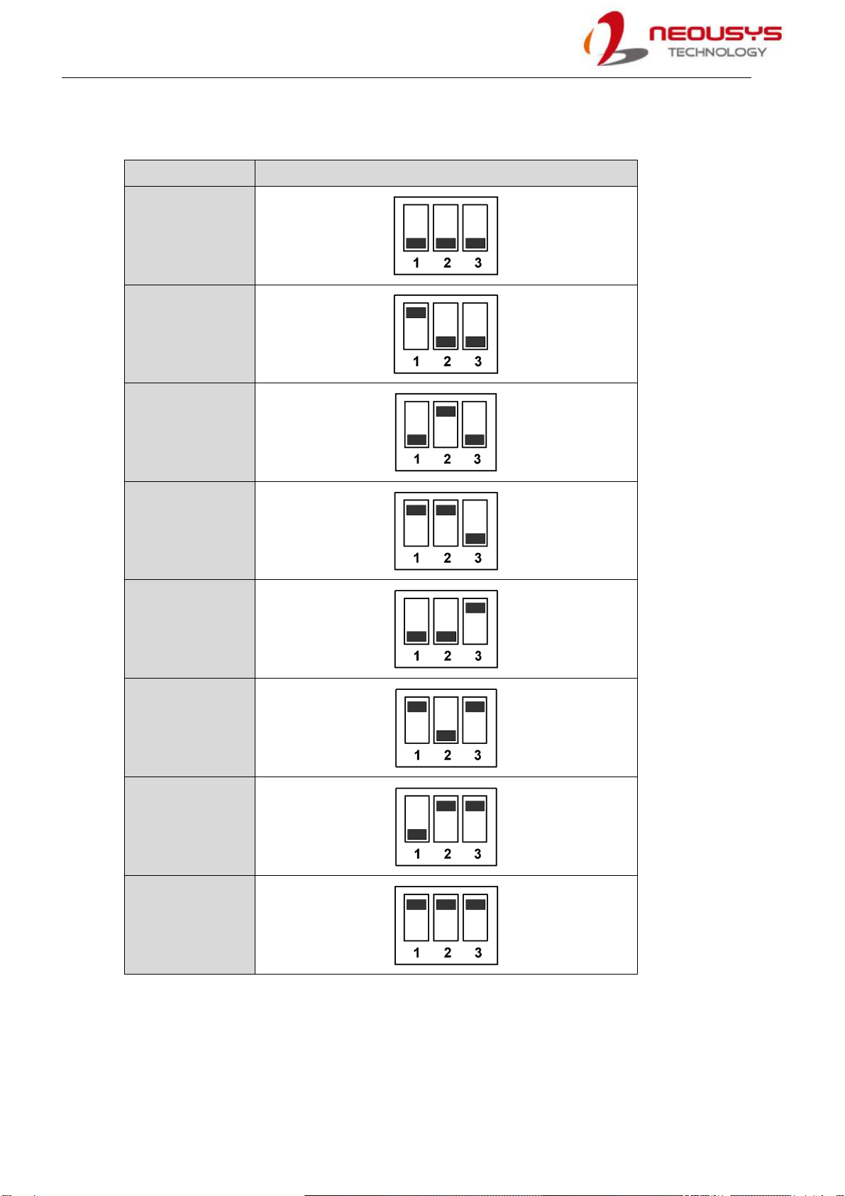
2.4.2 Board ID Settings
To set board IDs, please refer to the following table.
Board ID
DIP Switch Position (P1 ~ P3)
0
1
2
3
4
5
6
7
PCIe-USB380/ 340 Card
3 PCIe-USB Card Installation
Once you have set up your PCIe-USB card, current output for each port or if you are installing
multiple PCIe-USB cards, setting up the board ID, then you are ready to install the PCIe-USB card
into the system. To install the PCIe-USB card, please refer to the following procedure.
3.1 Hardware Installation
1. Save and close all work in progress.
2. Power off and unplug the power cable from the system you wish to install to.
3. Open the chassis (side panel) of the computer you wish to install the PCIe-USB card into.
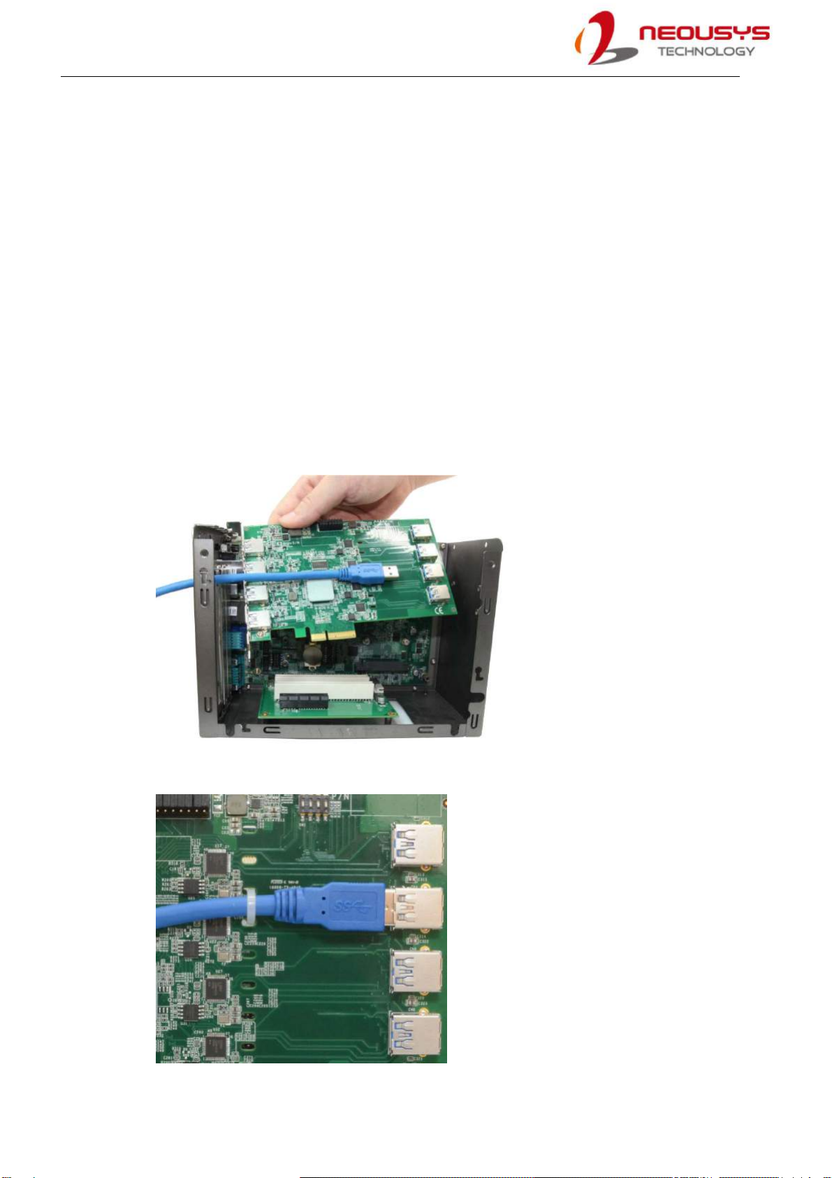
4. For PCIe-USB380, if you are going to connect to the internal USB ports, please do so before
installing the card into the computer. First, insert the cable through the panel opening
5. Second, plug in the USB connector and secure it using a cable tie.
PCIe-USB380/ 340 Card
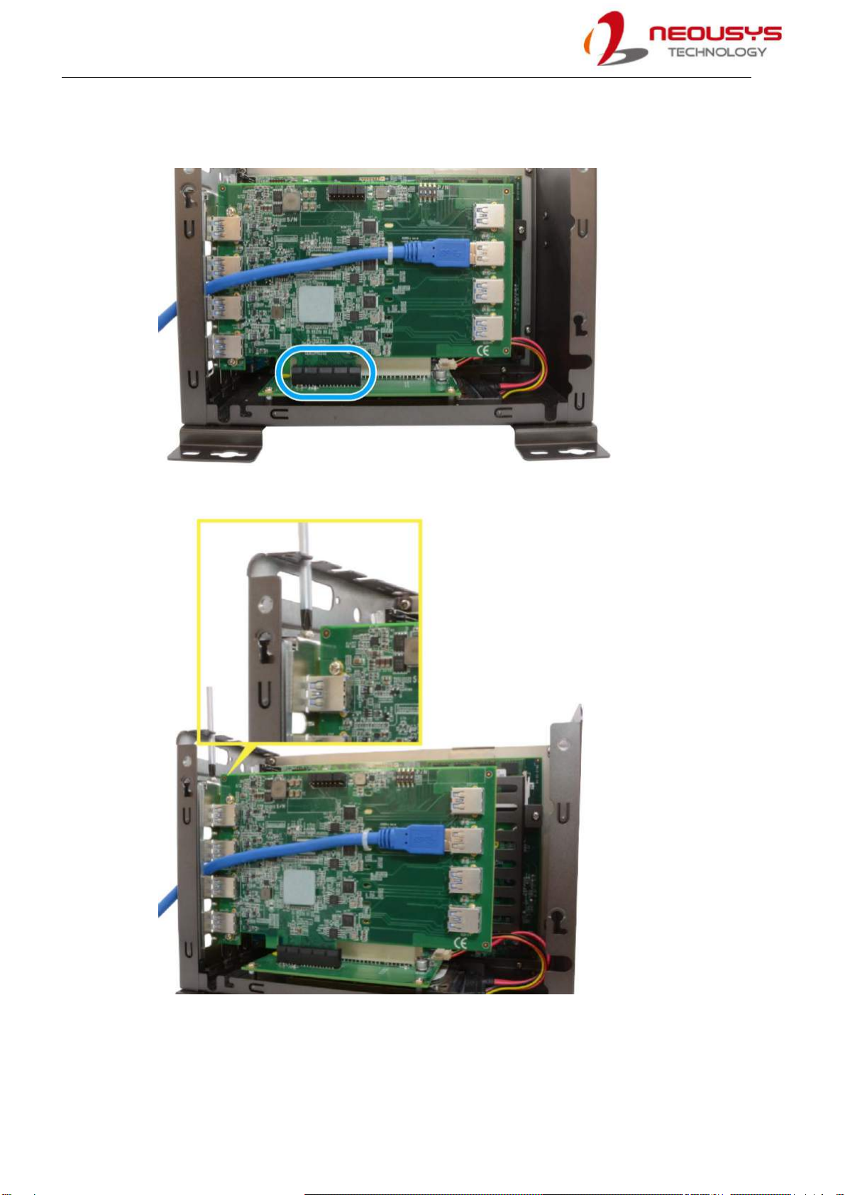
6. Locate the x4 PCIe slot or a spare and compatible x16 PCIe slot.
7. Align and insert PCIe-USB card’s gold finger into the PCIe slot.
8. Secure the PCIe-USB card to the chassis with a screw
9. Reinstall the system’s chassis (panel) to complete the hardware installation process.

PCIe-USB380/ 340 Card
3.2 Software Installation
Some operating system may have built-in drivers included and automatically complete the
installation upon entering the system. However, it is still recommended to run and install drivers
provided by Neousys to take advantage of all the functions offered. To install the software
component, please refer to the following procedure.
1. Plug in the power cable and power up the system.
2. Once you are in the system, insert the driver disc included in the package into the DVD-ROM.
3. Execute the file WIN_PCIE-USB380_340.exe, it may be located in the directory
x:\Driver_Pool\
4. If your system does not have a DVD-ROM, please go here to download the latest driver for
PCIe-USB380/340.
5. Simply follow instructions to complete the software installation process.
6. You may begin using your PCIe-USB card after hardware/ software components have been
installed.
Table of contents


