Ness 100-691 Quick start guide

4
Dimensions ................... 99(h) x 79(w) x 48(d) mm
Mounting height ............ 2.1m
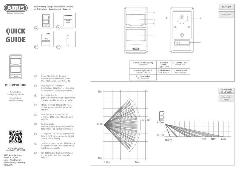
Coverage ...................... 12m x 12m @ 90°
Detector zones .............. 20 dual element zones
Pulse count ................... Selectable 1–2 or 3–4
Range ........................... Selectable High/Low
Sensor .......................... Dual element pyroelectric
Visual display ................ Red alarm LED
Alarm period ................. 5 seconds
Warm up period ............ 30 seconds
Operating voltage .......... 7-9V DC
Battery .......................... 9V Lithium (Ultralife U9VL)
Quiescent current draw . 16µA
Radio transmitter .......... SAWR stabilised
Radio frequency ............ 303.875MHz
Transmit power ............. 100µW PEP
SPECIFICATIONS
COVERAGE
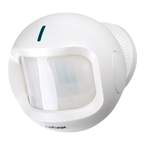
QUANTUM R12 RADIO PIR
INSTALLATION NOTES
Revision1, Feb 2002
Document part number: 890-277
For products: 100-691 Quantum R12 Radio PIR
© 2002 Ness Security Products Pty Ltd ABN 28 069 984 372
Specifications may change without notice.
R12 Radio PIR manual pmo140202
The detection pattern can be changed to suit
your application by changing the lens.
There are 3 lenses available:
WIDE ANGLE – 12m x 12m 90°
Supplied as standard
CURTAIN – 12m x 5° x Solid barrier
LONG RANGE – 25m x 13°
0.3m
2.1m
WIDE ANGLE (Supplied)
12m x 12m
1m 3m 6m 12m
2.1m
2.2m 3m 10.7m 18.3m 25m
5m
5m
2.5m
0
2.5m
0.3m
2.1m
CURTAIN
LONG RANGE
*Not to scale
1m 3m 6m 12m
7m
5.6°
INSTALLATION NOTES
PART NUMBER: 100-691
MODEL: Quantum R12 Radio PIR
FEATURES
• 12m x 12m wide angle coverage
• SAWR stabilised radio transmitter
• High R.F. and E.S.D. immunity
• High white light immunity
• Adjustable Pulse Count
• Adjustable range
• Long life Lithium battery supplied
• Up to 50m radio transmission range
• Low battery warning signal
• Hourly Supervision radio signals
• Separate battery compartment
• Automatic Test Mode disable
NESS SECURITY PRODUCTS
RADIO COMMUNICATIONS COMPLIANCE
Australian Communications Authority

2
MOUNTING LOCATION
This Passive Infra Red detector, (PIR), is
designed for indoor use only and can be
installed in wall or corner mount locations.
Always ensure the detector has a clear line of
sight of the area to be protected as infra-red
energy does not pass through solid objects,
(including glass).
Mount the detector in a location where an
intruder is most likely to walk across the
coverage pattern. Corner mounting usually gives
the best coverage.
As with all PIR detectors, it is advisable to choose
mounting positions which avoid direct sunlight,
heating or cooling sources and avoid areas of
high humidity which may cause condensation
on the lens.
Always install the detector away from metal
surfaces which may shield radio transmissions.
Before permanently mounting the detector, it is
recommended that you conduct a radio test
with the detector temporarily mounted in the
intended position.
Use the signal strength meter on the alarm
panel as guide to the best mounting position.
Often, a small change in position can have a
dramatic effect on radio performance due to
various environmental effects on radio signals.
INSTALLATION & TESTING
1 Remove the battery compartment lid by
sliding it down.
2 Open the detector’s front housing by
unclipping the bottom of the lid and swing it
open and away from the back housing.
3 Remove the circuit board from the
back-housing.
4 The base can be corner or flat surface
mounted. Drill holes as required for
mounting and mount the base securely filling
any gaps or holes with a flexible sealant such
as silicone.
5 Replace the board.
6 Set the link to the TEST position.
7 Set the RANGE and PULSE links to suit your
application (see Program Links).
8 Replace the cover, (reverse the removal
procedure).
9 Connect the battery.
10 Replace the battery compartment lid.
11 Wait approximately 30 seconds for the
detector to settle.
12 Walk test the coverage by walking slowly
across the protected area. The red alarm
light should indicate detection at a maximum
of 3 to 4 walking steps at a distance of 10m
from the detector.
Stop and wait for the red alarm light to turn
off before continuing walk testing.
13 If necessary, adjust the RANGE and PULSE
links to suit your installation. Always use the
lowest Range and highest Pulse setting for
any given area. Avoid the possibility of false
alarms caused by setting the detector too
sensitive for the environment.
RADIO TESTING
A preliminary radio test should be carried out
before permanently mounting the detector.
1 Set your control panel in signal strength
mode or detector test mode.
2 Test the detector as described in the section
Installation & Testing.
3 Ensure that the control panel has received
the alarm signal and that the signal strength
satisfactory.
MOUNTING HEIGHT
The recommended mounting height is 2.1m.
3
BATTERY
LOW BATTERY
The red alarm light, (LED), flashes every 2
seconds to indicate a low battery. This continues
for 4 minutes each time the detector is triggered.
The detector also transmits a low battery signal
to the control panel.
Low battery condition is triggered when the
battery voltage sinks to approximately 7 volts
under load.
When replacing the
battery, use only
Ultralife Lithium
U9VL or equivalent.
Alkaline and Carbon
batteries are not
recommended due
to their shorter
service life.
PROGRAM LINKS
TEST:
TEST link, disables the re-transmit timer, allowing
the detector to be walk tested without waiting
for the 4 minute timer to expire.
Note: If the TEST link is left on, the PIR will
automatically revert to normal mode after one
hour. This is a battery conservation feature.
To re-start test mode, remove the link and then
replace it.
PULSE
PULSE COUNT link selects two pulse count
positions.
LINK ON - 1–2 Pulses or walk steps should
cause an alarm.
LINK OFF - 3–4 Pulses or walk steps should
cause an alarm.
RANGE
The Range link selects 12m or 9m coverage
range.
LINK ON - 12m x 12m coverage
LINK OFF - 9m x 9m coverage
The RANGE link should be set to the minimum
setting that will guarantee detection of an
intruder at the extremities of the protected area.
Set the RANGE link to minimum Range (Link
OFF) unless otherwise required.
LED
Remove the link to disable the walk test LED.
RE-TRANSMIT TIME
To conserve battery life and limit unwanted radio
transmissions, the detector waits until all
detectable movement in the area has ceased
for at least 4 minutes before it will trigger and
transmit a new alarm.
This means that normal and constant movement
in the room will not cause the detector to transmit
multiple alarm signals.
There is no re-transmit delay in TEST mode.
RANGE
TEST
PULSE
LED
1-2
3-4
HIGH
LOW
ON
OFF
PULSE
COUNT
RANGE
105-389
SECURITY PRODUCTS
SUPERVISED RADIO PIR
9V BATTERY
This manual suits for next models
1
Other Ness Security Sensor manuals
