Net Safety VID-C User manual
Colour Explosion Proof Video Camera
USER MANUAL
VID-C
Part Number: MAN-0036-00 Rev 4


Copyright © 2002 Net Safety Monitoring Inc.
Printed in Canada
This manual is providedforinformational purposes only. Althoughthe informationcontained in this manual is
believedto be accurate, itcould include technical inaccuracies ortypographical errors. Changes are, therefore,
periodically made to the information within this document and incorporated without notice into subsequent
revisions of the manual. Net Safety Monitoring Inc. assumes no responsibility forany errors that may be
containedwithin this manual.
This manual is a guide forthe use of a VID-C and the data and procedures contained within this document have
been verified and are believed to be adequate forthe intendeduse of the camera . If the cameraorprocedures are
used forpurposes otherthan as described in the manual without receiving priorconfirmation of validity or
suitability, Net Safety Monitoring Inc. does not guarantee the results and assumes no obligation orliability.
No part of this manual may be copied, disseminated ordistributed without the express written consent of Net
Safety Monitoring Inc.
Net Safety Monitoring Inc. products, are carefully designed and manufactured fromhigh quality components and
can be expected to provide many years of trouble free service. Each product is thoroughly tested, inspected and
calibrated priorto shipment. Failures can occurwhich are beyond the control of the manufacturer. Failures can be
minimized by adhering to the operating and maintenance instructions herein. Where the absolute greatest of
reliability is required, redundancy should be designed into the system.
Net Safety Monitoring Inc., warrants its sensors and detectors against defective parts andworkmanship fora
period of 24 months fromdate of purchase and otherelectronic assemblies for36 months fromdate of purchase.
No otherwarranties orliability, expressed orimplied, will be honored by Net Safety Monitoring INC
Contact Net Safety Monitoring Inc. oran authorized distributorfordetails.

Table of Contents
Chapter1Introduction .................................................. 1
Description ............................................................................ 1
Features .............................................................................. 1
Chapter2InstallationandStartUp ....................................... 2
What’sinthepackage ................................................................... 2
LocationofCamera(s) ................................................................... 2
Figure1VID-CDimensionalDiagram ................................................. 3
Figure2SwivelMount............................................................. 4
VID-CWiring .......................................................................... 5
Figure 3 Wiring diagram for the VID-C colour video camera . . . . . . . . . . . . . . . . . . . . . . . . . . . . . . . 6
InstallationChecklist..................................................................... 7
StartUp .............................................................................. 7
Chapter3Troubleshooting .............................................. 7
Chapter4Maintenance ................................................. 8
AppendixATechnicalSpecifications ....................................... I
Appendix B Electrostatic Sensitive Device Handling Procedure . . . . . . . . . . . . . . . . II

1
Chapter 1 Introduction
Description
The NetSafety Monitoring Inc. VID-C explosion proof video camera is ideally suited forsafety
monitoring systems in hazardous locations. The colorvideo camera, mounted in anexplosion proof
housing, delivers acomposite video output foruse with most VCR's orvideo monitors. The wide
viewing angle provides forlarge areacoverage by one camera.
Features
<Full color video with optional black and white
<Compatible with industry standard CCTV hardware and software
<3 feet of video cable with RCA jack included
<Viewing angle of 52/horizontal
<High Resolution
<Extremely compact size

2
Chapter 2 Installation and Start Up
What’s in the package
Remove all the components fromthe packing box(s) carefully; checkcomponents against the packing list. Inspect
all components forobvious damage andbroken/loose parts. Notify the carrierand distributorimmediately if
damage is found orparts are missing.
Location of Camera(s)
Proper location of the VID-C is essential for providing maximum coverage. The most effective placement and
numbers of cameras varies depending onthe location. Experience, common sense, and knowledge of the areawill
determine the numberof cameras needed and the best locations to monitorthe area adequately.
The following factors are important and should be considered forevery installation:
<The VID-C should be located where it is safe frompotential sources of contamination i.e.
oil film, dirt.
<The VID-C must be accessible forcleaning.
<Exposure to excessive heat orvibration can cause premature failure of electronic devices
and should be avoided if possible.
Refer to figure 1 and 2 for installation information.
3
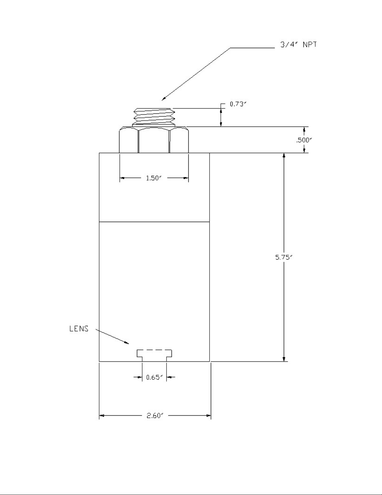
Figure 1 VID-C Dimensional Diagram

4
Figure 2 Swivel Mount

5
VID-C Wiring
NOTE
The VID-C contains semiconductor devices that are susceptible to damage by electrostatic discharge. An
electrostatic charge can build up on the skin and discharge when an object is touched. Therefore, use
caution when handling the device, taking care not to touch the terminals or electronic components. For
more information on proper handling, refer to 'Electrostatic Sensitive Device Handling Procedure', in
Appendix A.
Referto Figure 3 forwiring information. An RCA jackis terminatedat the end of the 3 footcoaxial cable.
Coaxial cable transmission is up to 1000 feet without amplification. Regular video cable
transmission is from 500 feet to 700 feet maximum.
NOTE:
The wiring procedures in this manual are intended to ensure proper functioning of the device under
normal conditions. However, because of the many variations in wiring codes and regulations, total
compliance to these ordinances cannot be guaranteed. Be certain that all wiring complies with
applicable regulations that relate to the installation of electrical equipment in a hazardous area. If in
doubt, consult a qualified official before wiring the system.

6
Figure 3 Wiring diagram for the VID-C colour video camera
The use of Coaxial cable is highly recommended for the video signal to protect against interference
caused by extraneous electrical “noise”.
Referto applicable wiring codes wheninstalling andwiring the VID-C. Afterthe fieldwiring has beencarefully
connected, checkthat the correct wires are connected to the corresponding terminals and that voltage levels do not
exceedthe specifications. When the wiring and voltages have beenverified remove powerform the system.

7
Installation Checklist
The following checklist is provided to check the systemand confirm that all phases of systeminstallation are
complete and have beenperformedcorrectly.
TVID-C is securely mounted
TAll wiring and cables are properly connected
Tpower source is operational
Start Up
With powerapplied, check thatyouare receiving a video signal onyourVCR orvideo monitor.
Chapter 3 Troubleshooting
The VID-C is not designedto be repaired in the field. If a problemshoulddevelop, carefully check forcorrect
wiring. If it is determined that the problem is caused by an electronic defect, the device must be returned to the
factory forrepair.
The unit is underfull warranty forTwo Years fromthe date of purchase.
Net Safety Monitoring Inc. supplies all distributors with advance replacement units. These units are available to
youduring the warranty period. This allows Net Safety Monitoring Inc. time to repairyourunit while youkeep
youroperations running smoothly.
Before returning devices or components, contact the nearest distributor so that an MRA (Material Return
Authorization) number can be assigned. A written statement describing the malfunction must accompany the
returned device or component to hasten finding the cause of the failure, thereby reducing the time and cost of the
repairto you. Use sufficient packing material inaddition to an anti-static bag oraluminum-backed cardboard as
protection from electrostatic discharge.

8
Chapter 4 Maintenance
To ensure reliable viewing, it is important to periodically clean the camera window. Although the frequency of
this cleaning is determined by the requirements of the particularprocess, it is recommended that the VID-C be
cleaned every year.
1 Using the included window cleaning kit (part number HDW-0061), clean the front side of the
window.

I
Appendix A
Technical Specifications
<Operating Voltage:
12V to 32 V
<PowerConsumption (at 24 Vdc):
2.0 W atts nominal.
70 mA nominal.
<Operating Temperature:
-25 C to +60 C (-13 F to +140 F).
ooo o
<Storage Temperature:
-40 C to +60 C (-40 F to +140 F).
ooo o
<Resolution:
Horizontal 350 TV lines.
<Numberof Pixels:
Total: 252K pixels; Effective: 512(H) 492(V)
<Dimensions:
Refer to Figure 1 and 2
<Shipping Weight (approximate):
1.6 Kg (3.5 lb)
<DetectorEnclosure Material:
Powder coated or anodized aluminum (Optional Stainless Steel)
<Certification:
Housing is certified to CSA. Certified ratings are; NEMA 4X for environmental protection and
CSA, Class I, Division 1 Groups B, C and D for hazardous locations.
<Viewing Angle
Horizontal 52o
<S/N (Signal to Noise ratio):
$46dB
<Output
1Vp-p, 75 ohms composite signal (NTSC)
<Connector:
Standard RCA Video Signal Connector

II
Appendix B
Electrostatic Sensitive Device Handling
Procedure
Electrostatic damage can occurin several ways. The most familiaris by physical contact. Touching an object
causes a discharge of electrostatic energy that has built up on the skin. If the charge is of sufficient magnitude, a
spark will also be visible. This voltage is often more than enough to damage some electronic components. Some
devices can be damaged without any physical contact. Exposure to an electric field can cause damage if the
electric field exceeds the dielectric breakdown voltage of the capacitive elements within the device.
In some cases, permanent damage is instantaneous and an immediate malfunction is realized. Often, however, the
symptoms are not immediately observed. Performance may be marginal orevenseemingly normal foran
indefinite period of time, followed by a sudden and mysterious failure.
Damage causedby electrostatic discharge can be virtually eliminated if the equipment is handled only ina static
safeguarded workarea and if it is transported in a package orcontainerthat will renderthe necessary protection
against static electricity. Net Safety Monitoring Inc. modules that might be damaged by static electricity are
carefully wrapped in a static protective material before being packaged. Foam packaging blocks are also treated
with an anti-static agent If it should everbecome necessary to return the module, it is highly recommended that it
be carefully packaged in the original carton and static protective wrapping.
Since astatic safeguardedwork area is usually impractical in most field installations, caution should be exercised
to handle the module by its metal shields, taking care notto touch electronic components orterminals.
In general, always exercise all of the acceptedandprovenprecautions that are normally observedwhenhandling
electrostatic sensitive devices.
A warning label is placed on the packaging, identifying those units that use electrostatic sensitive semiconductor
devices.
* Published in accordance with EIA standard 471


Table of contents


