manuals.online logo
Brands
  1. Home
  2. •
  3. Brands
  4. •
  5. NetApp
  6. •
  7. Network Hardware
  8. •
  9. NetApp ASA C Series Instruction sheet

NetApp ASA C Series Instruction sheet

This manual suits for next models

11

Other NetApp Network Hardware manuals

NetApp FC4600 User manual

NetApp

NetApp FC4600 User manual

NetApp E2600 User manual

NetApp

NetApp E2600 User manual
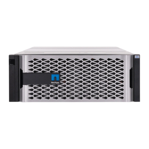
NetApp AFF A400 User manual

NetApp

NetApp AFF A400 User manual
NetApp E Series User manual

NetApp

NetApp E Series User manual

NetApp AFF A400 User manual

NetApp

NetApp AFF A400 User manual
NetApp ASA C250 Instruction sheet

NetApp

NetApp ASA C250 Instruction sheet
NetApp AFF A320 User manual

NetApp

NetApp AFF A320 User manual

NetApp AFF A900 Manual

NetApp

NetApp AFF A900 Manual

NetApp AFF C250 Manual

NetApp

NetApp AFF C250 Manual
NetApp NS224 User manual

NetApp

NetApp NS224 User manual

NetApp ASA A250 User manual

NetApp

NetApp ASA A250 User manual
NetApp AFF A Series Manual

NetApp

NetApp AFF A Series Manual
NetApp StorageGRID Webscale SG5700 Series Operating manual
NetApp

NetApp StorageGRID Webscale SG5700 Series Operating manual

NetApp StorageGRID 11.5 Operating manual
NetApp

NetApp StorageGRID 11.5 Operating manual

NetApp AFF C400 Manual

NetApp

NetApp AFF C400 Manual

NetApp NS224 User manual

NetApp

NetApp NS224 User manual

NetApp AFF A400 Instructions for use

NetApp

NetApp AFF A400 Instructions for use
NetApp ASA A400 User manual

NetApp

NetApp ASA A400 User manual

NetApp AFF A250 User manual

NetApp

NetApp AFF A250 User manual
NetApp AFF C190 Instruction sheet

NetApp

NetApp AFF C190 Instruction sheet

Popular Network Hardware manuals by other brands

socomec SNMP Card II quick start guide

socomec

socomec SNMP Card II quick start guide

NVR SYSTEMS 4-CH user manual

NVR SYSTEMS

NVR SYSTEMS 4-CH user manual

Draytek VigorSwitch G1240 quick start guide

Draytek

Draytek VigorSwitch G1240 quick start guide

Westermo TD-34 LV installation manual

Westermo

Westermo TD-34 LV installation manual

LaCie Network Space MAX Quick install guide

LaCie

LaCie Network Space MAX Quick install guide

ZoneVu ZSI-450-IP Installation guide & user manual

ZoneVu

ZoneVu ZSI-450-IP Installation guide & user manual

QNAP Turbo NAS Application notes

QNAP

QNAP Turbo NAS Application notes

OpenEye MV Series quick start guide

OpenEye

OpenEye MV Series quick start guide

Huawei SmartAX MT880a quick start guide

Huawei

Huawei SmartAX MT880a quick start guide

Proxim Tsunami QuickBridge 2454-R installation guide

Proxim

Proxim Tsunami QuickBridge 2454-R installation guide

Bay Networks CLAM quick start guide

Bay Networks

Bay Networks CLAM quick start guide

Innodisk SATADOM-SH 3SE Series manual

Innodisk

Innodisk SATADOM-SH 3SE Series manual

Cisco CGR 1000 Series Getting connected guide

Cisco

Cisco CGR 1000 Series Getting connected guide

Matrix Switch Corporation MSC-HD161DEL product manual

Matrix Switch Corporation

Matrix Switch Corporation MSC-HD161DEL product manual

National Instruments NI 653x user manual

National Instruments

National Instruments NI 653x user manual

B&B Electronics ZXT9-IO-222R2 product manual

B&B Electronics

B&B Electronics ZXT9-IO-222R2 product manual

Yudor YDS-16 user manual

Yudor

Yudor YDS-16 user manual

D-Link ShareCenter DNS-320L datasheet

D-Link

D-Link ShareCenter DNS-320L datasheet

manuals.online logo
manuals.online logoBrands
  • About & Mission
  • Contact us
  • Privacy Policy
  • Terms and Conditions

Copyright 2025 Manuals.Online. All Rights Reserved.

ASA C-series systems
Install and maintain
NetApp
October 20, 2023
This PDF was generated from https://docs.netapp.com/us-en/ontap-systems/asa-c250/install-setup.html
on October 20, 2023. Always check docs.netapp.com for the latest.
Table of Contents
All SAN Array (ASA) C-series Systems . . . . . . . . . . . . . . . . . . . . . . . . . . . . . . . . . . . . . . . . . . . . . . . . . . . . . . . . Ê1
ASA C250 systems . . . . . . . . . . . . . . . . . . . . . . . . . . . . . . . . . . . . . . . . . . . . . . . . . . . . . . . . . . . . . . . . . . . . . Ê1
All SAN Array (ASA) C-series Systems
ASA C250 systems
Install and setup
Start here: Choose your installation and setup experience
For most configurations, you can choose from different content formats.
•Quick steps
A printable PDF of step-by-step instructions with live links to additional content.
•Video steps
Video step-by-step instructions.
•Detailed steps
Online step-by-step instructions with live links to additional content.
If your system is in a MetroCluster IP configuration, see the Install MetroCluster IP Configuration instructions.
Quick steps - ASA C250
This section gives graphic instructions for a typical installation of your system from
racking and cabling, through initial system bring-up. Use this guide if you are familiar with
installing NetApp systems.
Access the Installation and Setup Instructions PDF poster:
•English: ASA A250 Installation and Setup Instructions
•Japanese: ASA A250 Systems Installation and Setup Instructions
•Chinese: ASA A250 Systems Installation and Setup Instructions
Videos - ASA C250
The following video shows how to install and cable your new system.
Animation - Installation and Setup of an AFF A250
The ASA C250 uses the same installation procedure as the AFF A250 system.
Detailed steps - ASA C250
This section gives detailed step-by-step instructions for installing an ASA C250 system.
1
Step 1: Prepare for installation
To install your AFF A250 system, you need to create an account and register the system. You also need to
inventory the appropriate number and type of cables for your system and collect specific network information.
Customers with specific power requirements must check HWU for their configuration options.
Before you begin
•Make sure you have access to the NetApp Hardware Universe (HWU) for information about site
requirements.
•Make sure you have access to the Release Notes for your version of ONTAP for more information about
this system.
•You need to provide the following at your site:
◦Rack space for the storage system
◦Phillips #2 screwdriver
◦Additional networking cables to connect your system to your network switch and laptop or console with
a Web browser
Steps
1. Unpack the contents of all boxes.
2. Record the system serial number from the controllers.
3. Set up your account:
a. Log in to your existing account or create an account.
b. Register your system.
4. Download and install NetApp Downloads: Config Advisor on your laptop.
5. Inventory and make a note of the number and types of cables you received.
The following table identifies the types of cables you might receive. If you receive a cable not listed in the
table, see the NetApp Hardware Universe to locate the cable and identify its use.
Type of cable… Part number and length Connector type For…
25 GbE cable X66240A-05 (112-00595), 0.5m;
X66240-2 (112-00573), 2m
Cluster interconnect network
X66240A-2 (112-00598), 2m;
X66240A-5 (112-00600), 5m
Data
100 GbE cable X66211-2 (112-00574), 2m;
X66211-5 (112-00576), 5m
Storage
2
Type of cable… Part number and length Connector type For…
RJ-45 (order
dependent)
Not applicable Management network (BMC and
wrench port) and Ethernet data
(e0a and e0b)
Fibre Channel X66250-2 (112-00342) 2m;
X66250-5 (112-00344) 5m;
X66250-15 (112-00346) 15m;
X66250-30 (112-00347) 30m
Micro-USB
console cable
Not applicable Console connection during
software setup
Power cables Not applicable Powering up the system
6. Review the ONTAP Configuration Guide and collect the required information listed in that guide.
Step 2: Install the hardware
You need to install your system in a 4-post rack or NetApp system cabinet, as applicable.
Steps
1. Install the rail kits, as needed.
2. Install and secure your system using the instructions included with the rail kit.
You need to be aware of the safety concerns associated with the weight of the system.
3. Identify and manage cables because this system does not have a cable management device.
4. Place the bezel on the front of the system.
Step 3: Cable controllers to cluster
Cable the controllers to a cluster by using the two-node switchless cluster method or by using the cluster
interconnect network method.
3
Option 1: Two-node switchless cluster
The management, Fibre Channel, and data or host network ports on the controller modules are
connected to switches. The cluster interconnect ports are cabled on both controller modules.
Before you begin
•Contact your network administrator for information about connecting the system to the switches.
•Be sure to check the illustration arrow for the proper cable connector pull-tab orientation.
As you insert the connector, you should feel it click into place; if you do not feel it click,
remove it, turn it around and try again.
About this task
Use the animation or the tabulated steps to complete the cabling between the controllers and the
switches. Perform the steps on each controller.
Animation - Cable two-node switchless cluster
Steps
1. Use the the 25GbE cluster interconnect cable to connect the cluster interconnect ports e0c to e0c and
e0d to e0d.
:
2. Cable the wrench ports to the management network switches with the RJ45 cables.
4
DO NOT plug in the power cords at this point.
Option 2: Switched cluster
All ports on the controllers are connected to switches; cluster interconnect, management, Fibre Channel,
and data or host network switches.
Before you begin
•Contact your network administrator for information about connecting the system to the switches.
•Be sure to check the illustration arrow for the proper cable connector pull-tab orientation.
As you insert the connector, you should feel it click into place; if you do not feel it click,
remove it, turn it around and try again.
About this task
Use the animation or the steps to complete the cabling between the controllers and the switches. Perform
the steps on each controller.
Animation - Cable switched cluster
Steps
1. Cable the cluster interconnect ports e0c and e0d to the 25 GbE cluster interconnect switches.
2. Cable the wrench ports to the management network switches with the RJ45 cables.
5
Step 4: Cable to host network or storage (Optional)
You have configuration-dependent optional cabling to the Fibre Channel or iSCSI host networks or direct-
attached storage. This cabling is not exclusive; you can have cabling to a host network and storage.
NetApp Hardware Universe slot priority for host network cards (Fibre Channel or 25GbE) is slot
2. However, if you have both cards, the Fibre Channel card goes in slot 2 and the 25GbE card
goes in slot 1 (as shown in the options below). If you have an external shelf, the storage card
goes in slot 1, the only supported slot for shelves.
6
Option 1: Cable to Fibre Channel host network
Fibre Channel ports on the controllers are connected to Fibre Channel host network switches.
Before you begin
•Contact your network administrator for information about connecting the system to the switches.
•Be sure to check the illustration arrow for the proper cable connector pull-tab orientation.
As you insert the connector, you should feel it click into place; if you do not feel it click,
remove it, turn it around and try again..
About this task
Perform the following step on each controller module.
Steps
1. Cable ports 2a through 2d to the FC host switches.
Option 2: Cable to 25GbE data or host network
25GbE ports on the controllers are connected to 25GbE data or host network switches.
Before you begin
•Contact your network administrator for information about connecting the system to the switches.
•Be sure to check the illustration arrow for the proper cable connector pull-tab orientation.
7
As you insert the connector, you should feel it click into place; if you do not feel it click,
remove it, turn it around and try again.
About this task
Perform the following step on each controller module.
Steps
1. Cable ports e4a through e4d to the 10GbE host network switches.
Option 3: Cable controllers to single drive shelf
Cable each controller to the NSM modules on the NS224 drive shelf.
Before you begin
Be sure to check the illustration arrow for the proper cable connector pull-tab orientation.
As you insert the connector, you should feel it click into place; if you do not feel it click,
remove it, turn it around and try again.
About this task
Use the animation or the tabulated steps to complete the cabling between the controllers and the single
shelf. Perform the steps on each controller module.
Animation - Cable the controllers to a single NS224
Steps
1. Cable controller A to the shelf.
8