Netgate SG-1000 User manual

Product Manual
SG-1000
Netgate
Dec 07, 2017

CONTENTS
1 SG-1000 Quick Start Guide 2
1.1 I/O Ports ................................................. 3
1.2 Getting Started .............................................. 5
1.3 Connecting to Console Port ....................................... 15
1.4 Additional Resources ........................................... 21
1.5 Warranty and Support Information .................................... 22
1.6 Safety and Legal ............................................. 22
2 SG-1000 FAQ 30
2.1 How do I restore the firewall OS? (firmware) .............................. 30
2.2 How do I reset to factory defaults? .................................... 31
2.3 Is the CPU temperature too high? .................................... 32
2.4 What should my speed test results be? .................................. 32
2.5 Is booting from USB OTG supported? .................................. 32
2.6 What packages are available? ...................................... 32
2.7 Why isn’t “my favorite package” available? ............................... 34
2.8 Why do I see failure messages in the BIOS output while booting? ................... 34
2.9 The boot environment on eMMC is corrupted and it will not boot from Micro-SD ........... 35
3 Reinstalling pfSense 36
i

Product Manual, SG-1000
Thank you for your purchase of the pfSense® SG-1000 System This hardware platform provides a powerful, reliable,
cost-effective solution.
Quick Start Guide
The SG-1000 Quick Start Guide covers the first time connection procedures and will provide you with the information
you need to get your appliance up and running.
Premium Documentation
Included with the purchase of an eligible appliance is access to The pfSense Book (700+ pages of premium online
documentation and guides). Make sure you have activated your bundled support to gain access.
Frequently Asked Questions
For answers to basic questions about the SG-1000 platform, consult the SG-1000 FAQ.
References
•Reinstalling pfSense
CONTENTS 1

CHAPTER
ONE
SG-1000 QUICK START GUIDE
This Quick Start Guide covers first time connection procedures for a new appliance.
2

Product Manual, SG-1000
Table of Contents
1.1 I/O Ports
Ports are assigned as pictured.
Front
• LAN (cpsw1)
• WAN (cpsw0)
Note: Both the WAN and LAN ports of the pfSense appliance support auto-MDIX and are capable of utilizing either
straight-through or crossover ethernet cables.
Back
• Console (Micro-USB)
• USB OTG
• Status LED
• Power
Internal
The Micro-SD card socket uses a sliding lock cover, not a push-style mechanism.
To install a Micro-SD card:
• Gently slide the cover toward the network interface port to unlock it
• Raise the lid
• Place the Micro-SD card in the socket, contacts down
• Gently close the lid
• Slide the cover toward the power connector to lock it in place
Tip: If the cover will not close gently, check the alignment of the Micro-SD card as it may not be settled completely
into the socket in the correct place.
1.1. I/O Ports 3

Product Manual, SG-1000
Fig. 1.1: Installing a Micro-SD card in the SG-1000
1.1. I/O Ports 4

Product Manual, SG-1000
1.2 Getting Started
Tip: Before configuring the pfSense appliance it is best to activate the bundled Gold by following the instructions at
https://www.netgate.com/register/.
The basic firewall configuration begins with connecting the pfSense appliance to the Internet. Neither the modem nor
the pfSense appliance should be powered up at this time.
Establishing a connection to the Internet Service Provider (ISP) starts with connecting one end of an ethernet cable to
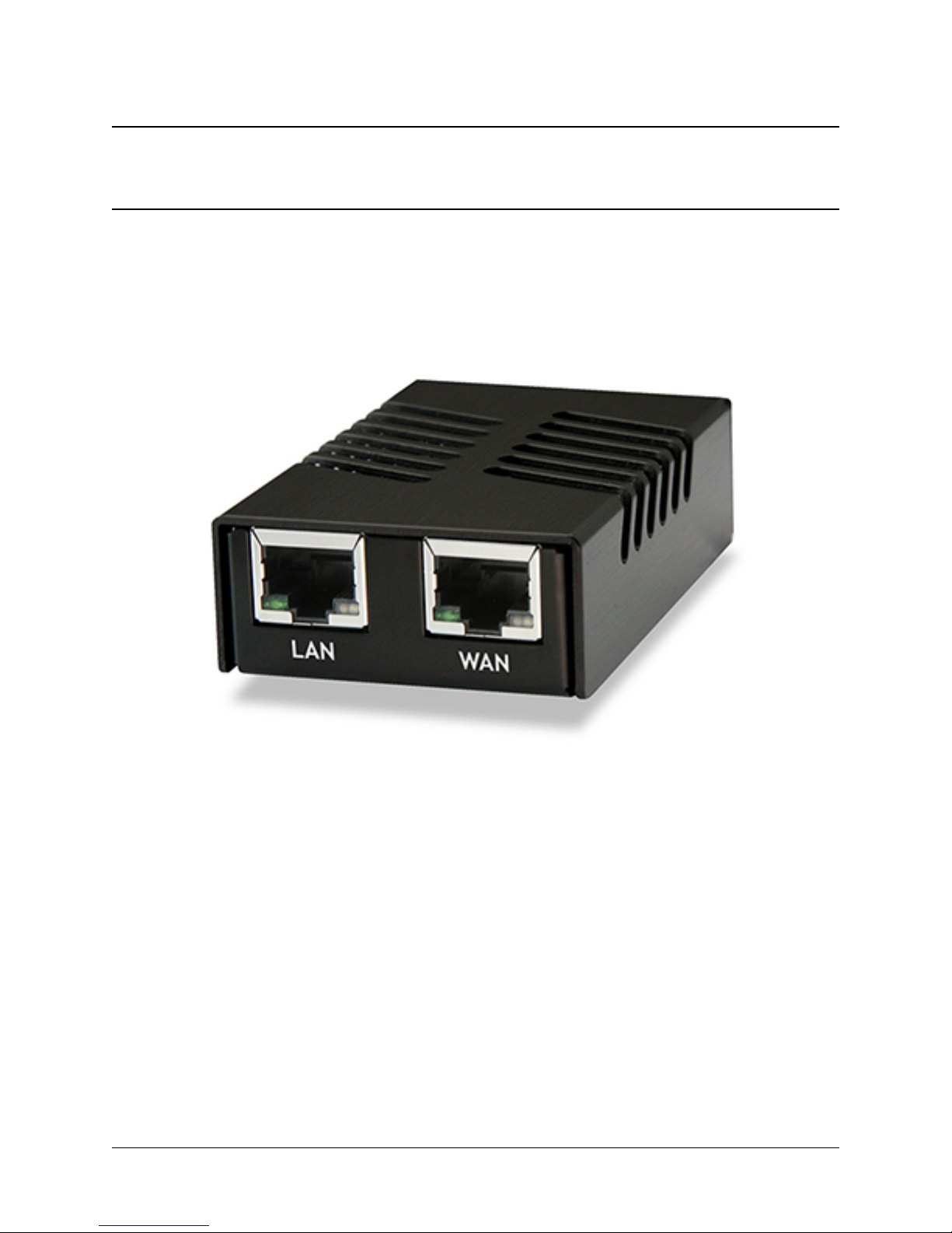
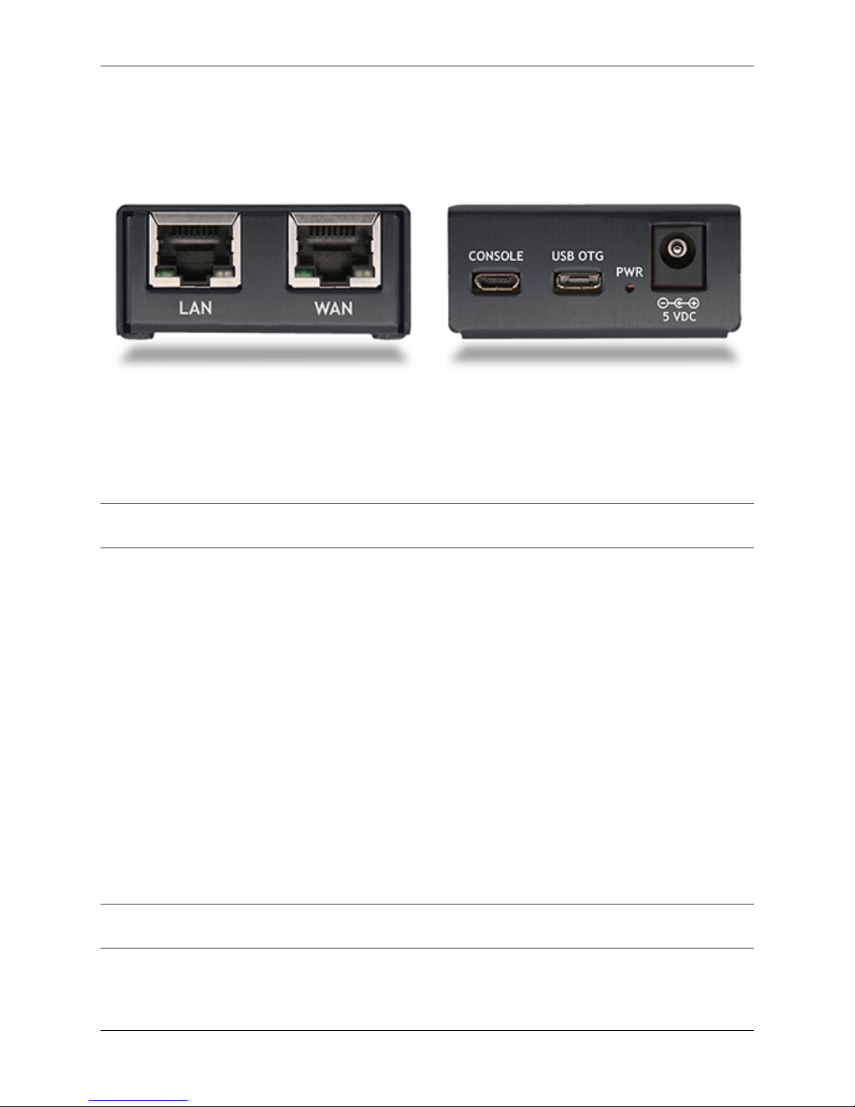
the WAN port (shown in the I/O Ports section) of the pfSense appliance.
Warning: The default LAN subnet on the firewall is 192.168.1.0/24. The same subnet cannot be used on
both WAN and LAN, so if the subnet on the WAN side of the firewall is also 192.168.1.0/24,disconnect the
WAN interface until the LAN interface has been renumbered to a different subnet.
The opposite end of the same ethernet cable should be inserted in to the LAN port of the ISP-supplied modem. The
modem provided by the ISP might have multiple LAN ports. If so, they are usually numbered. For the purpose of this
installation, please select port 1.
The next step is to connect the LAN port (shown in the I/O Ports section) of the pfSense appliance to the computer
which will be used to access the firewall console.
Connect one end of the second ethernet cable to the LAN port (shown in the I/O Ports section) of the pfSense appliance.
Connect the other end to the network connection on the computer. In order to access the web configurator, the PC
network interface must be set to use DHCP, or have a static IP set in the 192.168.1.x subnet with a subnet mask
of 255.255.255.0. Do not use 192.168.1.1, as this is the address of the firewall, and will cause an IP conflict.
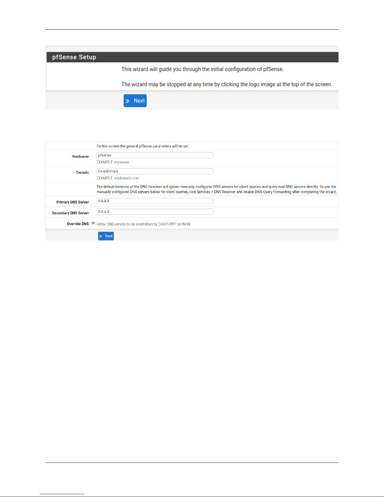
1.2.1 Initial Setup
The next step is to power up the modem and the firewall. Plug in the power supply to the power port (shown in the I/O
Ports section).
Once the modem and pfSense appliance are powered up, the next step is to power up the computer.
Once the pfSense appliance is booted, the attached computer should receive a 192.168.1.x IP address via DHCP
from the pfSense appliance.
1.2.2 Logging Into the Web Interface
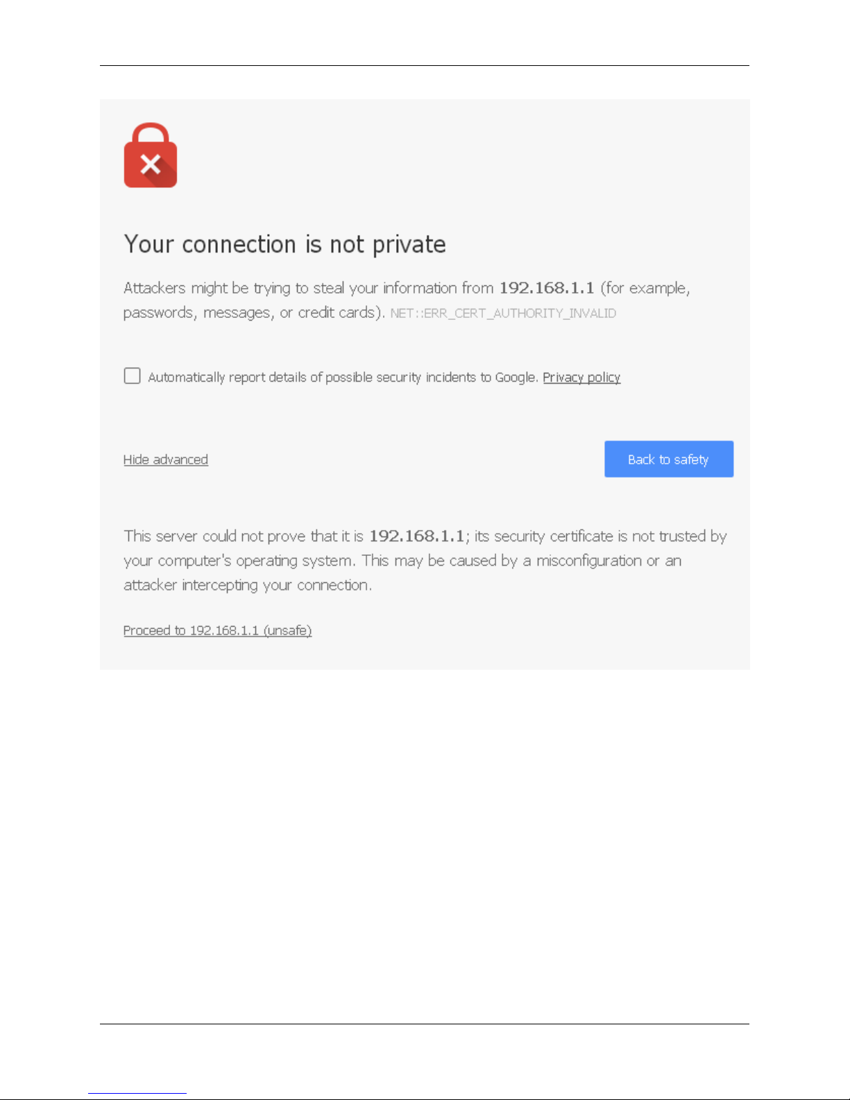
Browse to https://192.168.1.1 to access the web interface. In some instances, the browser may respond with a message
indicating a problem with website security. Below is a typical example in Google Chrome. If this message or similar
message is encountered, it is safe to proceed.
1.2. Getting Started 5

Product Manual, SG-1000
At the login page enter the default pfSense password and username:
Username admin
Password pfsense
Click Login to continue
1.2.3 Wizard
Upon successful login, the following is displayed.
1.2. Getting Started 6

Product Manual, SG-1000
1.2.4 Configuring Hostname, Domain Name and DNS Servers
1.2.5 Hostname
For Hostname, any desired name can be entered as it does not affect functionality of the firewall. Assigning a hostname
to the firewall will allow the GUI to be accessed by hostname as well as IP address.
For the purposes of this guide, use pfsense for the hostname. The default hostname, pfsense may be left un-
changed.
Once saved in the configuration, the GUI may be accessed by entering http://pfsense as well as http://192.168.1.1
1.2.6 Domain
If an existing DNS domain is in use within the local network (such as a Microsoft Active Directory domain), use that
domain here. This is the domain suffix assigned to DHCP clients, which should match the internal network.
For networks without any internal DNS domains, enter any desired domain name. The default localdomain is used
for the purposes of this tutorial.
1.2.7 DNS Servers
The DNS server fields can be left blank if the DNS Resolver is used in non- forwarding mode, which is the default
behavior. The settings may also be left blank if the WAN connection is using DHCP, PPTP or PPPoE types of Internet
connections and the ISP automatically assigns DNS server IP addresses. When using a static IP on WAN, DNS server
IP addresses must be entered here for name resolution to function if the default DNS Resolver settings are not used.
1.2. Getting Started 7

Product Manual, SG-1000
DNS servers can be specified here even if they differ from the servers assigned by the ISP. Either enter the IP addresses
provided by the ISP, or consider using Google public DNS servers (8.8.8.8,8.8.4.4). Google DNS servers are
used for the purpose of this tutorial. Click Next after filling in the fields as appropriate.
1.2.8 Time Server Configuration
1.2.9 Time Server Synchronization
Setting time server synchronization is quite simple. We recommend using the default pfSense time server address,
which will randomly select an NTP server from a pool.
1.2.10 Setting Time Zone
Select an appropriate time zone for the location of the firewall. For purposes of this manual, the Timezone setting will
be set to America/Chicago for US Central time.
1.2.11 Configuring Wide Area Network (WAN) Type
The WAN interface type is the next to be configured. The IP address assigned to this section becomes the Public IP
address that this network will use to communicate with the Internet.
This depicts the four possible WAN interface types. Static, DHCP, PPPoE and PPTP. One must be selected from the
drop-down list.
Further information from the ISP is required to proceed when selecting Static,PPPoE and PPTP such as login name
and password or as with static addresses, an IP address, subnet mask and gateway address.
1.2. Getting Started 8

Product Manual, SG-1000
DHCP is the most common type of interface for home cable modems. One dynamic IP address is issued from the
ISP DHCP server and will become the public IP address of the network behind this firewall. This address will change
periodically at the discretion of the ISP. Select DHCP as shown and proceed to the next section.
1.2.12 MAC Address
If replacing an existing firewall, the WAN MAC address of the old firewall may be entered here, if it can be determined.
This can help avoid issues involved in switching out firewalls, such as ARP caches, ISPs locking to single MAC
addresses, etc.
If the MAC address of the old firewall cannot be located, the impact is most likely insignificant. Power cycle the ISP
router and modem and the new MAC address will usually be able to get online. For some ISPs, it may be necessary to
call them when switching devices, or an activation process may be required.
1.2.13 Configuring MTU and MSS
MTU or Maximum Transmission Unit determines the largest protocol data unit that can be passed onwards. A 1500-
byte packet is the largest packet size allowed by Ethernet at the network layer and for the most part, the Internet so
leaving this field blank allows the system to default to 1500-byte packets. PPPoE is slightly smaller at 1492-bytes.
Leave this blank for a basic configuration.
1.2.14 Configuring DHCP Hostname
Some ISPs specifically require a DHCP Hostname entry. Unless the ISP requires the setting, leave it blank.
1.2. Getting Started 9

Product Manual, SG-1000
1.2.15 Configuring PPPoE and PPTP Interfaces
Information added in these sections is assigned by the ISP. Configure these settings as directed by the ISP
1.2.16 Block Private Networks and Bogons
When enabled, all private network traffic originating on the internet is blocked.
Private addresses are reserved for use on internal LANs and blocked from outside traffic so these address ranges may
be reused by all private networks.
1.2. Getting Started 10

Product Manual, SG-1000
The following inbound address Ranges are blocked by this firewall rule:
•10.0.0.1 to 10.255.255.255
•172.16.0.1 to 172.31.255.254
•192.168.0.1 to 192.168.255.254
•127.0.0.0/8
•100.64.0.0/10
•fc00::/7
Bogons are public IP addresses that have not yet been allocated, so they may typically also be safely blocked as they
should not be in active use.
Check Block RFC1918 Private Networks and Block Bogon Networks.
Click Next to continue.
1.2.17 Configuring LAN IP Address & Subnet Mask
A static IP address of 192.168.1.1 and a subnet mask (CIDR) of 24 was chosen for this installation. If there are
no plans to connect this network to any other network via VPN, the 192.168.1.x default is sufficient.
Click Next to continue.
Note: If a Virtual Private Network (VPN) is configured to remote locations, choose a private IP address range more
obscure than the very common 192.168.1.0/24. IP addresses within the 172.16.0.0/12 RFC1918 private
address block are the least frequently used. We recommend selecting a block of addresses between 172.16.x.x
and 172.31.x.x for least likelihood of having VPN connectivity difficulties. An example of a conflict would be If
the local LAN is set to 192.168.1.x and a remote user is connected to a wireless hotspot using 192.168.1.x
(very common), the remote client won’t be able to communicate across the VPN to the local network.
1.2. Getting Started 11

Product Manual, SG-1000
1.2.18 Change Administrator Password
Select a new Administrator Password and enter it twice, then click Next to continue.
1.2.19 Save Changes
Click Reload to save configuration.
1.2.20 Basic Firewall Configured
To proceed to the webConfigurator, make the selection as highlighted. The Dashboard display will follow.
1.2. Getting Started 12

Product Manual, SG-1000
1.2.21 Backing Up and Restoring
At this point, basic LAN and WAN interface configuration is complete. Before proceeding, backup the firewall con-
figuration. From the menu at the top of the page, browse to Diagnostics > Backup/Restore.
1.2. Getting Started 13

Product Manual, SG-1000
Click Download Configuration and save a copy of the firewall configuration.
This configuration can be restored from the same screen by choosing the backup file under Restore configuration.
1.2. Getting Started 14

Product Manual, SG-1000
1.2.22 Connecting to the Console
There are times when accessing the console is required. Perhaps GUI console access has been locked out, or the
password has been lost or forgotten.
See also:
Connecting to Console Port Connect to the console. Cable is required.
Tip: Included with each appliance is a one year subscription to pfSense Gold (Video tutorials, 700+ pages of premium
online documentation, and more).
1.3 Connecting to Console Port
1.3.1 Simple Configuration
Below are the simple instructions for connecting to the console port with Microsoft Windows. If these steps do not
work for you or if you’re an operating system other than Windows, then please skip forward to Advanced Configura-
tion.
Serial Terminal Emulation Client
A serial terminal emulation program is required to access the pfSense appliance console through the serial interface.
Microsoft Windows no longer includes HyperTerminal in Versions 7 and up. PuTTY is free and can be downloaded
from:
http://www.chiark.greenend.org.uk/~sgtatham/putty/download.html
Configuring Serial Terminal Emulator
PuTTY must be configured to communicate with the pfSense appliance. In order to do so, you must first know what
COM Port your computer has assigned to your serial port. Even if you assigned your serial port to COM1 in the BIOS,
Windows may remap it to a different COM Port. To determine this, you must open Windows Device Manager and
view the COM port assignment.
1.3. Connecting to Console Port 15

Product Manual, SG-1000
Open PuTTY and locate the Session display as shown. Set the COM Port to that which is displayed in Windows
Device Manager and the Speed to 115200.
1.3. Connecting to Console Port 16

Product Manual, SG-1000
Match the COM Port with what was reported in Windows Device Manager. We will use COM3 for this example. The
pfSense appliance serial port speed is 115200 bits per second. The speed of the BIOS and the speed of the console
must match so change the speed in PuTTy to 115200bps.
Select Serial as shown and configure the COM Port and Serial Speed as displayed. Select Open and the conolse
screen will be displayed.
1.3.2 Advanced Configuration
A Silicon Labs CP210x USB-to-UART bridge is used to provide access to the serial port that acts as a system console.
This is exposed via a Micro-USB B port on the front of the case. There are several steps required to access the system
console via this port.
1.3. Connecting to Console Port 17

Product Manual, SG-1000
Install the Driver
Install an appropriate CP210x USB to UART Bridge VCP (virtual COM port) driver on the workstation used to connect
with the system if needed. There are drivers available for Windows, Mac OS X, and Linux available in the Download
Software section of the Silicon Labs Website.
Warning: Do not download the SDK, only download the driver.
Note: Recent versions of FreeBSD and many Linux distributions include this driver and will not require manual
installation.
Loading the Linux Driver
If the device does not appear automatically, the CP210x driver module may need to be loaded manually, especially if
the version of Linux being run is not recent. If the driver was provided with the Linux distribution, run modprobe
cp210x as root or using sudo. If it had to be built manually, run insmod ./cp210x.ko assuming the module is
in the current directory.
Connect a USB Cable
Next, locate an appropriate USB cable. The type of cable required for the serial console has a Micro-USB B connector
on one end and a regular USB (Type A) plug on the other end. These cables are commonly used with smaller USB
peripherals such as GPS units, cameras, and so on.
Attach the USB cable between a workstation and the system. Gently push the Mini-B plug end into the console port
on the system and connect the USB type A plug into an available USB port on the workstation.
Note: Be certain to gently push in the Mini-B connector on the system side completely. With most cables there will
be a tangible “click”, “snap”, or similar indication when the cable is fully engaged.
Locate the Console Port Device
The appropriate device to attach the terminal program to each platform varies by platform and must be located before
attempting to connect to the console.
Windows
To locate the device name on Windows, open Device Manager and expand the section for Ports (COM & LPT).
Look for an entry with a title such as Silicon Labs CP210x USB to UART Bridge. If there is a label in the name
that contains “COMX” where X is a decimal digit (e.g. COM1), that value is what would be used as the port in the
terminal program.
1.3. Connecting to Console Port 18
This manual suits for next models
2
Table of contents
Other Netgate Firewall manuals
Popular Firewall manuals by other brands

Trend Micro
Trend Micro TippingPoint NX-Platform Hardware Installation and Safety

SonicWALL
SonicWALL Email Security 800 Getting started guide

Trend Micro
Trend Micro txOne Networks EdgeIPS Quick setup guide

IBM
IBM QRadar XGS 5200 Replacement instructions

ZyXEL Communications
ZyXEL Communications ZyWALL SSL 10 user guide

Asus
Asus AAEON FWS-2276 user manual