BESTEK NSP-10H6 User manual

1
Network Security System
NSP-10H6
Always at the forefront of innovation
User Manual
2
Thispublicationcontainsinformationthatisprotectedbycopyright.Nopartofitmaybereproducedinany
formorbyanymeansorusedtomakeanytransformationadaptationwithoutthepriorwrittenpermission
fromthecopyrightholders.
Thispublicationisprovidedforinformationalpurposesonly.Themanufacturermakesnorepresentationsor
warrantieswithrespecttothecontentsoruseofthismanualandspecificallydisclaimsanyexpressorimplied
warrantiesofmerchantabilityorfitnessforanyparticularpurpose.Theuserwillassumetheentireriskofthe
useortheresultsoftheuseofthisdocument.Further,themanufacturerreservestherighttorevisethis
publicationandmakechangestoitscontentsatanytime,withoutobligationtonotifyanypersonorentityof
suchrevisionsorchanges.
©2011.AllRightsReserved.
Alltrademarksandregisteredtrademarksofproductsappearinginthismanualarethepropertiesoftheir
respectiveholders.
ThisequipmenthasbeentestedandfoundtocomplywiththelimitsforaClassAdigitaldevice,pursuantto
Part15oftheFCCrules.Theselimitsaredesignedtoprovidereasonableprotectionagainstharmful
interferencewhentheequipmentisoperatedinaresidentialinstallation.Thisequipmentgenerates,uses,
andcanradiateradiofrequencyenergyand,ifnotinstalledandusedinaccordancewiththeinstruction
manual,maycauseharmfulinterferencetoradiocommunications.However,thereisnoguaranteethat
interferencewillnotoccurinaparticularinstallation.Ifthisequipmentdoescauseharmfulinterferenceto
radioortelevisionreception,whichcanbedeterminedbyturningtheequipmentoffandon,theuseris
encouragedtotrytocorrecttheinterferencebyoneormoreofthefollowingmeasures:
Reorientorrelocatethereceivingantenna.
Increasetheseparationbetweentheequipmentandthereceiver.
Connecttheequipmentintoanoutletonacircuitdifferentfromthattowhichthereceiverisconnected.
ConsultthedealeroranexperiencedradioTVtechnicianforhelp.
Notice:
1. Thechangesormodificationsnotexpresslyapprovedbythepartyresponsibleforcompliancecouldvoid
theuser’sauthoritytooperatetheequipment.
2. Shieldedinterfacecablesmustbeusedinordertocomplywiththeemissionlimits.
Copyright
Trademarks
FCC and DOC Statement on Class A

3
1. Warrantydoesnotcoverdamagesorfailuresthatareraisedfrommisuseoftheproduct,inabilitytouse
theproduct,unauthorizedreplacementoralterationofcomponentsandproductspecifications.
2. Thewarrantyisvoidiftheproducthasbeensubjecttophysicalabuse,improperinstallation,modification,
accidentsorunauthorizedrepairoftheproduct.
3. Unlessotherwiseinstructedinthisuser’smanual,theusermaynot,underanycircumstances,attemptto
performservice,adjustmentsorrepairsontheproduct,whetherinoroutofwarranty.Itmustbe
returnedtothepurchasepoint,factoryorauthorizedserviceagencyforallsuchwork.
4. Wewillnotbeliableforanyindirect,special,incidentalorconsequentialdamagestotheproductthathas
beenmodifiedoraltered.
ItisquiteeasytoinadvertentlydamageyourPC,systemboard,componentsordevicesevenbeforeinstalling
theminyoursystemunit.Staticelectricaldischargecandamagecomputercomponentswithoutcausingany
signsofphysicaldamage.Youmusttakeextracareinhandlingthemtoensureagainstelectrostaticbuild‐up.
1. Topreventelectrostaticbuild‐up,leavethesystemboardinitsanti‐staticbaguntilyouarereadytoinstall
it.
2. Wearanantistaticwriststrap.
3. Doallpreparationworkonastatic‐freesurface.
4. Holdthedeviceonlybyitsedges.Becarefulnottotouchanyofthecomponents,contactsorconnections.
5. Avoidtouchingthepinsorcontactsonallmodulesandconnectors.Holdmodulesorconnectorsbytheir
ends.
Important:
Electrostaticdischarge(ESD)candamageyourprocessor,diskdriveandother
components.PerformtheupgradeinstructionproceduresdescribedatanESD
workstationonly.Ifsuchastationisnotavailable,youcanprovidesomeESD
protectionbywearinganantistaticwriststrapandattachingittoametalpartofthe
systemchassis.Ifawriststrapisunavailable,establishandmaintaincontactwiththe
systemchassisthroughoutanyproceduresrequiringESDprotection.
Warrant
y
Static Electricit
y
Precautions
4
Toavoiddamagetothesystem:
•UsethecorrectACinputvoltagerange.
Toreducetheriskofelectricshock:
•Unplugthepowercordbeforeremovingthesystemchassiscoverforinstallationorservicing.After
installationorservicing,coverthesystemchassisbeforepluggingthepowercord.
Battery:
•Dangerofexplosionifbatteryincorrectlyreplaced.
•Replaceonlywiththesameorequivalenttyperecommendbythemanufacturer.
•Disposeofusedbatteriesaccordingtolocalordinance.
Beforeusingthesystem,preparebasicsystemcomponents.
Ifthesystemcomesasabarebone;thatis,noneofthekeycomponents,includingprocessor,memory,and
harddrivehasbeenpre‐installedaspartofyourpurchase,youwillneedtoatleastensureacompatible
counterpartislocatedandinstalled.
Youwillalsoneedafewexternalsystemperipheralsintendedfortheuseofthesystem,acommonpoolwith
atleastakeyboard,amouse,andamonitoristhussuggested.
Safet
y
Measures
Before Usin
g
the S
y
stem

5
Table of Content
Copyright....................................................................................................................................................................
2
Trademarks....................................................................................................................................................................
2
FCCandDOCStatementOnClassA..............................................................................................................................2
Warranty........................................................................................................................................................................3
StaticElectricityPrecautions.........................................................................................................................................3
SafetyMeasures............................................................................................................................................................4
BeforeUsingtheSystemBoard.....................................................................................................................................4
TableofContent............................................................................................................................................................5
Chapter1GeneralInformation
1.1Main
Feature...........................................................................................................................................................7
1.2
Specifications.......................................................................................................................................................
8
1.3OptionalLANModules.....................................................................................................................................9
1.4SystemLayout.................................................................................................................................................10
1.5IndicatorsandFeatures..................................................................................................................................11
Chapter2Preparation
2.1BeforeYouBegin.....................................................................................................................................14
2.2
Precautions.........................................................................................................................................................
14
2.3OpenUpTopCover
.............................................................................................................................................
15
2.4AccessingProcessor&Memory..........................................................................................................................16
2.5Adding2.5”/3.5”SATAHardDrive.....................................................................................................................16
2.6AccessingCompactFlashCard........................................................................................................................18
Chapter3Operation
3.1TurningOnTheSystem....................................................................................................................................20
3.2Installing
OperatingSystem&Drivers........................................................................................................
21
3.3UnderstandingLEDIndicators........................................................................................................................22
Chapter4BIOSSetup
4.1EnteringSetup................................................................................................................................................25
4.2GettingHelp....................................................................................................................................................25
4.3ControlKeys....................................................................................................................................................25
4.4TheMainMenu...............................................................................................................................................26
4.5TheAdvancedMenu........................................................................................................................................27
4.6TheChipsetMenu.....................................................................................................................................................30
4.7TheBootMenu................................................................................................................................................31
4.8TheSecurityMenu..........................................................................................................................................33
4.9TheSave&ExitMenu.....................................................................................................................................34
Chapter5ProgrammingGuide............................................................................................36
Chapter6Q&A...................................................................................................................38

6
Chapter 1
General Information

7
ProcessorPerformance
NSP‐10H6isa1URackMountNetworkSecuritySystemthat,pre‐installedwithBNX‐H61securityboard,
featuringonIntel®H61chipset,supportsIntel®Gen‐2/3LGA1155Celeron®,Pentium®,Core®‐i3/i5/i7
processorsthatcarrythebuilt‐inIntel®HDGraphicengine.Belowisabrieflistofavailableprocessorsasa
quickreference:
Celeron®Processor:G540/G1620
Pentium®Processor:G850/G2120
Core®‐i3Processor:i3‐2120/i3‐3220
Core®‐i5Processor:i5‐2400/i5‐3550S
Core®‐i7Processor:i7‐2600/i7‐3770
8GBMemoryfor64bitOS
ThetwoDualChannelDDR3DIMMslotsaredesignedtocarryupto16GBDDR31066/1333/1600MHz
SDRAMwithNon‐ECCsupport,ideallyfacilitatingapplicationsthatdemandtotalmemorycapacityforthe
useof64bitOS,beyondthe4GBbarrierinherentinthe32bitOS.
Onboard/ModuleGigabitLANPorts
ThesixonboardIntel®PCIeGigabit82583VLANControllersdeliveroutstandingnetworkperformance
with2‐pairdual‐latchbypassfunctionsthatareconfigurablethroughBIOSsettingorsoftware
programmingandareundervisualmonitoringviatheLEDindicationsatfrontpanel.Yesfurtheraccessto
fullstatusisalsoavailableviasoftwareprogramming.Oneexpansionslotisdesignedtomaketheunit
expandableuptoadditional4‐portcopper(RJ45)Gigabitportsor4‐portfiber(SFP)Gigabitports,bothon
Intel®82580EBchip,maximizingthesystemuptoatotal10‐portGigabitPorts,onlywithina1Urack
mountenclosure.BelowisalistofallavailableLANmodules:
4‐PortRJ45GigabitLANModuleonIntel®82580EB
4‐PortSFPGigabitLANModuleonIntel®82580EB
ListofKeyFeatures
Intel®H61Chipset
Intel®LGA1155Gen‐2/3DesktopCeleron®,Pentium®,Core®‐i3/i5/i7Processor
TwoDDR3RAMSlotsupto16GB
Oneinternal3.5”SATADrive,ortwointernal2.5”SATADrives
OneCompactFlashSocket
OneSATADOMPort
OneDB15VGAatrearside
TwoUSB2.0Portsatfront
SixIntel®GigabitLANPortsatfront
OneRJ45ConsolePortatfront
OneExpansionSlotforuptoadditional4‐PortGigabitLANModule
1U300WFlex‐ATXPowerSupply
1URackMountof365mmDepth
1.1 MainFeature

8
Core Engine Chipset Intel® H61 PCH
Processor Support Intel® Gen-2/3 LGA1155 Processor
Memory 2x DDR3-1066/1333/1600 DIMM Slots for up to 16GB
Display CPU Integrated (Intel® HD Graphics 2500/4000)
Ethernet Controller 6x Onboard Intel® 82583V GbE Controllers
ByPass 2-Pair Dual-Latch
LAN Module Support 1x PCIe X8 Slot for LAN Module
Storage SATA 1x 3.5” (or 2x 2.5”) SATA2 Drive Bay
SATADOM 1x SATADOM Socket
CF 1x CompactFlash Socket
Front I/O Indication 1x Power LED, 1x HDD LED, 2x Bypass LED
LAN 6x RJ45 Ports
Console 1x RJ45 Type Console Port
USB 2x USB 2.0 Ports
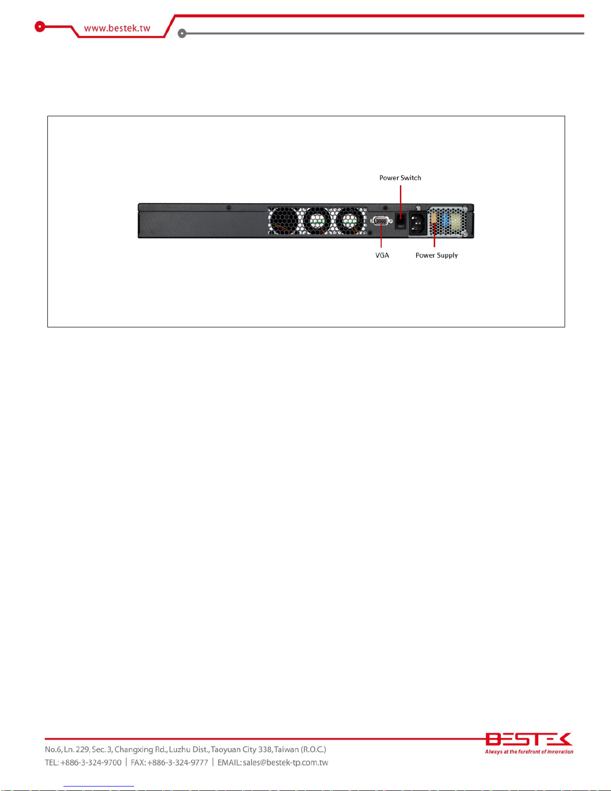
Rear I/O Switch 1x Rock Type Power Switch
VGA 1x Optional DB15 VGA Port
Expansion PCIe 1x Straddle Type PCIe X8 Slot
Power Type Internal 300W Single Power Supply, 100-240Vac, 50-60Hz
Cooling CPU Fan 1x CPU Cooler with Blower Fan
System Fan 2x 40mm System Fans at rear side
Other H/W Monitoring
Monitor temperature, voltage, and fan speed, auto-throttling control at CPU overheat
LCM Character Type 1x Optional 2x16 LCM with 5x Programmable Keys
Environment
Operating Temp. 0oC ~ 40oC
Storage Temp. -20oC ~ 70oC
Humidity 10% ~ 90% (Non-Condensing)
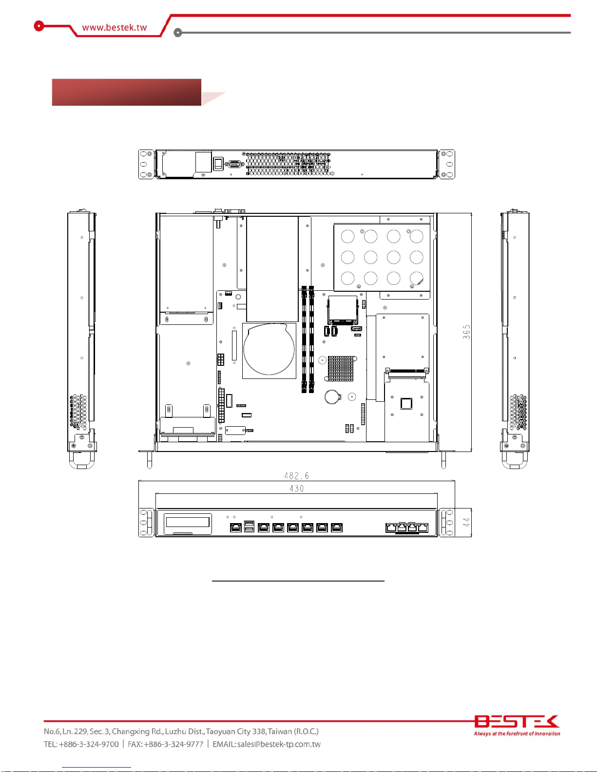
Mechanical Dimension 430mm (W) x 365mm (D) x 44mm (H)
1.2 Specifications

9
BEM-C600-580-C4 Type LAN Module
Chipset Intel® 82580EB
Interface PCIe X4
Network Port Four RJ45 Gigabit
Bypass 1-Pair
BEM-C600-580-F4 Type LAN Module
Chipset Intel® 82580EB
Interface PCIe X4
Network Port Four SFP Fiber Gigabit
1.3 OptionalLANModules
10
Figure1.1:SystemLayoutofNSP‐10H6
1.4 SystemLayout

11
►FrontView
With4‐PortRJ45LANModule
With4‐PortSFPLANModule
1.5 Indicators&Features
12
►RearView

13
Chapter 2
Preparation
14
Astableandcleanworkingenvironmentareessential.Dustanddirtcangetintocomponentsandcausea
malfunction.Usecontainerstokeepsmallcomponentsseparated.
Adequatelightingandpropertoolscanpreventyoufromaccidentallydamagingtheinternalcomponents.Most
oftheproceduresthatfollowrequireonlyafewsimpletools,includingthefollowing:
APhilipsscrewdriver
Aflat‐tippedscrewdriver
AsetofjewelersScrewdrivers
Agroundingstrap
Ananti‐staticpad
Usingyourfingerscandisconnectmostoftheconnections.Itisrecommendedthatyoudonotuse
needle‐nosedplierstodisconnectconnectionsasthesecandamagethesoftmetalorplasticpartsofthe
connectors.
Beforeworkingoninternalcomponents,makesurethatthepowerisoff.Groundyourselfbeforetouchingany
internalcomponents,bytouchingametalobject.Staticelectricitycandamagemanyoftheelectronic
components.Humidenvironmenttendtohavelessstaticelectricitythandry
environments.
Agroundingstrapis
warrantedwheneverdangerofstaticelectricityexists.
Computercomponentsandelectroniccircuitboardscanbedamagedbydischargesofstaticelectricity.Wo r k i n g
onthecomputersthatarestillconnectedtoapowersupplycanbeextremelydangerous.Followtheguidelines
belowtoavoiddamagetoyourcomputeroryourself:
Alwaysdisconnecttheunitfromthepoweroutletwheneveryouareworkinginsidethecase.
Ifpossible,wearagroundedwriststrapwhenyouareworkinginsidethecomputercase.Alternatively,
dischargeanystaticelectricitybytouchingthebaremetalchassisoftheunitcase,orthebare
metalbody
ofanyothergroundedappliance.
Holdelectroniccircuitboardsbytheedgesonly.Nevertouchthecomponentsontheboardunlessitis
necessarytodoso.Donotflexorstressthecircuitboard.
Leaveallcomponentsinsidethestatic‐proofpackagingthattheyshippedwithuntiltheyarereadyfor
installation.
Usecorrectscrewsanddonotovertightenscrews.
2.1 BeforeYouBegin
2.2
Precautions

15
Thisisthefirststepofalltoproceedwith,ifyouaretoinstall(orchange)aprocessor(harddriveormemory
module).
Pleaseremovethe2screwsatthebackasindicatedintheplacesbelow,priortoanymovingofthetopcover.
Itisrecommendedtopushthetopcoverbackwardssoastodetachthecovertongueoutofthesnatch‐upat
frontside,beforethelift‐uporremovalofthetopcover.
Securingthescrewsisessentialfortheywouldbere‐usedfortherestorationofthetopcover,afterall
preparationproceduresarecompleted.
2.3
OpenUpTopCover

16
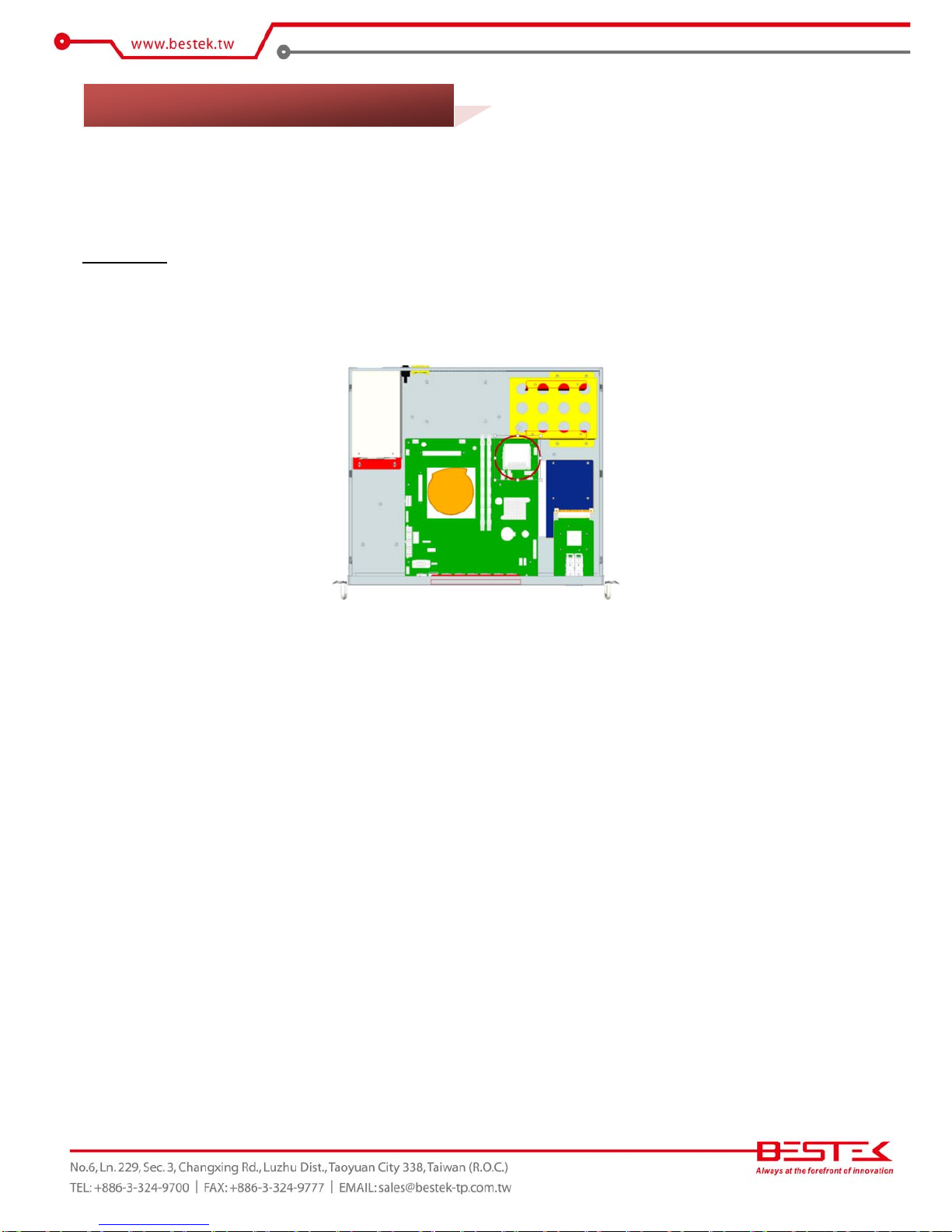
PleaserefertotheManualofBNX‐H61motherboardforsubstantialdetailsastoaddingprocessor,cooler,and
memory.
Procedures:
(1) Turnoffthesystemandopenupthetopcover.
(2) FindthefourscrewsfastenedontheHardDrivebracket(redcirclesasbelow).Removethesescrewstoacquire
theHardDrivebracket.
(3) ThisHardDrivebracketisdesignedtoholdone3.5”SATADrive,withalsotwosmallerL‐bracketfortwo2.5”
SATADrives.PleasefindthefourscrewsfastenedonthetopoftheHardDrivebracket(bluearrowsasbelow)to
detachthetwosmallerL‐brackets.
2.4 AccessingProcessor&Memory
2.5 Adding2.5”/3.5”SATAHardDrive

17
(4) Addthe3.5”HardDrive:Asillustratedbelow,pleasehavethe3.5”HardDriveassembledwiththisHardDrive
bracket,leavingtheHardDriveI/Oattheendasinthefigurebelow,andaddinthesuggestednumeric
sequencethefourscrewsenclosedintheaccessoryscrewbag,foraperfectandfirmHardDrivesubset.
(5) Addthetwo2.5”HardDrives:Asillustratedbelow,pleasehavethetwo2.5”HardDriveassembledwiththetwo
smallerL‐brackets,leavingtheHardDriveI/Oateitherendasthebracketsaresymmentricallydesigned,and
addtheeightscrewsenclosedintheaccessoryscrewbag,foraperfectandfirmHardDrivesubset.Incaseonly
one2.5”HardDriveistobeinstalled,addthisHardDriveoneithertoporbottompositiontomakethesubset.
Attachthefinished2.5”subsetintotheHardDrivebracket,ensuringHDDDriveI/Oareatthesimilarpositionas
inthe3.5”HardDrivesection,andaddthefourscrewsfromthetoptocompletethejob.
(6) RestorethisHardDrivesubsetbacktothechassis,assuretheHardDriveI/Osidefacetothepowersupplyunit,
andaddthefourscrewsbacktoposition.
(7) AddSATAsignalcableandSATApowercabletocompletethework.
18
CompactFlashinsteadofCFast
NSP‐10H6comeswithoneCompactFlashcardsocket,ratherthanCFastcardsocket.Pleasebecarefulwhen
addingyourflashdevices.
Procedures:
(1) Turnoffthesystem.
(2) TheonboardCompactFlashsocketcanbelocatedonmotherboard(astheredcircle).
(3) PleasedetachtheHardDrivebracketbeforeinserting,removing,orswappingaCompactFlash.
(4) RestoreHardDrivebracketifneeded.
PleasebeadvisedthatCompactFlashcardonIDEinterfaceisnevertobeaddedorremovedwhenthe
systempowerisstillturnedon;thatis,noplug‐and‐playschemeisenabledforthisdevice.Disrespectof
suchalimitationwouldverylikelyleadtosysteminstabilityormalfunction,oreventotheworstafatal
systemcatastrophe.PleasealwaysturnoffsystempowerbeforeaccessingCompactFlashcard.
2.6 AccessingCompactFlashCard

19
Chapter 3
Operation

20
Addyourcables,suchasUSBkeyboard,USBmouse,andDB15VGACableasthemerestdevicestocontrolthe
system.
WatchInputACPowerRange
PleaseleavetheACpowercordasthelastcabletobeadded,rightontheACInletasindicatedbelowwith
bluecircle.TheACinputrangeofthebuilt‐inPowerSupplyis100‐240Vac.IfyourACinputisnotwithinthis
range,thoughrarelypossibleinfact,itisnotcompliantwiththesystemandyoushouldnotplugintheAC
powercord.
SystemIsUpOnACPower
Insomecases,dependingonwhetheraBIOSsettinghasbeenconfiguredtoallowimmediatepower‐onupon
thedeliveryofACpower,systemmightcomerightupunexpectedlyfornoparticularreason.Pleasereferto
BIOSsectionfordetailswith“RestoreOnACPowerLoss”.Haveyouwishtobringitdown,simplypressonce
onthepowerswitch(locatednexttopowersupplywithyellowcircle),orpressandholdfor4seconds,to
reachthatgoal.However,inmostoccasions,withoutsuchabrupteventasstatedabove,simplypressonceon
thePowerSwitchtoturnonthesystem.
PowerLED
ThepowerLEDcanbefoundatfrontpanelandshallcomelitconstantONatsystemstart.
HDDLED
TheHDDLEDcanalsobefoundatfrontpanelandshallblinkinthewakeofstorageactivity,suchasSATAdrive
orCompactFlash.
Firstscreen&OptimalBIOSSetting
Oncethesystemsuccessfullybootsup,itshallactivatedisplaysignalonmonitor,disclosingsomesystem
informationascheckpointsfordebugging,thereafterusersareencouragedtobringupBIOSsetupmenutoat
leastloadtheoptimalBIOSsetting,asthefirstthingtodoatpoweron.PleaserefertotheBIOSsectionfor
substantialdetails.
3.1 TurningOnTheSystem
Table of contents
Other BESTEK Firewall manuals


Popular Firewall manuals by other brands


NETGEAR
NETGEAR SRX5308 - ProSafe® Quad WAN Gigabit SSL VPN... Reference manual

Hirschmann
Hirschmann EAGLE 20 TX/TX user manual

Hirschmann
Hirschmann EAGLE 20 Series Reference manual

finjan
finjan Vital Security NG-1000 Installation and setup guide

NETGEAR
NETGEAR ProSAFE SRX5308 Cli reference manual

Sophos
Sophos XGS 2100 quick start guide

Draytek
Draytek Vigor 2820 Series Specifications

Ubiquiti
Ubiquiti UCK-G2 quick start guide

Fortinet
Fortinet FortiGate FortiGate-60B quick start guide

Symantec
Symantec 10268947 - Network Security 7160 user guide

Allied Telesis
Allied Telesis AR Router Series Technical guide

H3C
H3C SecPath F5000 Series Compliance and Safety Manual