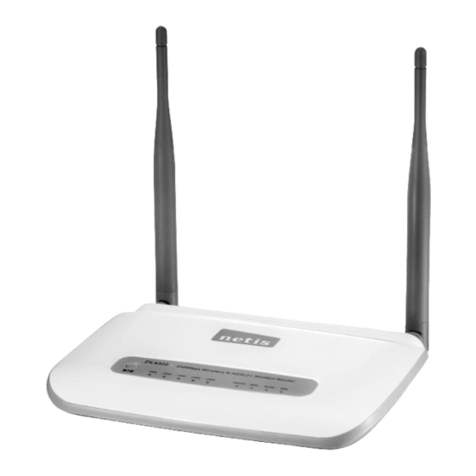
Netronix W440A User manual

802.11g WirelessRouter
User sManual

FCC Certifications
FederalCommunication Commission Interference Statement
Thisequipmenthasbeentestedandfoundtocomplywiththelimitsfora
Class Bdigitaldevice,pursuanttoPart15 ofthe FCC Rules.These
limitsaredesignedtoprovide reasonableprotectionagainstharmful
interferenceinaresidentialinstallation.Thisequipmentgenerates,uses
andcanradiateradiofrequency energyand,ifnotinstalled andusedin
accordancewiththe instructions,maycauseharmfulinterferencetoradio
communications.However,thereisno guarantee thatinterferencewill
notoccurinaparticularinstallation.Ifthisequipmentdoescause
harmfulinterferencetoradioortelevision reception,whichcanbe
determinedbyturningtheequipmentoffandon,the userisencouraged
totrytocorrecttheinterferencebyoneofthefollowing measures:
-Reorient orrelocatethereceivingantenna.
-Increasetheseparationbetweenthe equipmentand receiver.
-Connecttheequipment intoanoutleton acircuitdifferent fromthat
towhichthereceiverisconnected.
-Consultthedealeroranexperiencedradio/TVtechnicianforhelp.
ThisdevicecomplieswithPart15of theFCC Rules.Operation issubject
tothefollowing twoconditions:(1)Thisdevicemaynotcauseharmful
interference,and(2)thisdevicemustacceptanyinterferencereceived,
including interferencethatmaycauseundesired operation.
FCC Caution:Anychangesormodificationsnotexpresslyapprovedby
thepartyresponsibleforcompliancecouldvoidtheuser'sauthorityto
operatethisequipment.
IMPORTANTNOTE:
FCC Radiation ExposureStatement:
Thisequipment complieswithFCC radiationexposurelimitssetforthfor
an uncontrolledenvironment. Thisequipment shouldbe installedand
operated withminimumdistance20cmbetweentheradiator&yourbody.
Thistransmittermustnotbe co-locatedoroperating inconjunction with
anyotherantennaortransmitter.
IEEE 802.11b or802.11g operationofthisproductintheU.S.A.is
firmware-limitedtochannels1through 11.

CEMarkWarning
Thisequipment complieswiththe requirements
relating toelectromagneticcompatibility, EN55022 class BforITE,
the essentialprotection requirement of CouncilDirective
89/336/EECon theapproximation of the lawsof the MemberStates
relating toelectromagneticcompatibility.
Companyhasan on-goingpolicy of upgradingitsproductsandit
maybe possiblethatinformation inthisdocument isnot up-to-date.
Pleasecheck withyourlocaldistributorsforthelatestinformation.
Nopart of thisdocument can be copied orreproduced inanyform
without writtenconsent fromthe company.
Trademarks:
Alltradenamesand trademarks arethe propertiesof their
respectivecompanies.
Copyright 2006,AllRightsReserved.

TableofContents
UnpackingInformation 1
IntroductionToWireless Router 2
GeneralDescription 2
KeyFeatures 3
The Front Panel 4
System LEDs 4
Port LEDs(Wireless) 4
Port LEDs(WAN) 4
Port LEDs(LAN) 5
The RearPanel 5
PowerConnection 5
Placement (Optional) 5
RestoreDefaultButton 6
InstallingAndUsingWireless Router 7
Networkconfiguration setup 7
Computerconfiguration setup 8
Management 10
WirelessRouterconfiguration setup 10
Setup Wizard 12
Operation Mode 16
Wireless 17
BasicSettings 17
AdvancedSettings 19
Security 21
AccessControl 23
WDS Setting 24
TCP/IP Setting 25

LANInterfaceSetup 25
WANInterfaceSetup 26
StaticIPMode 26
FirewallConfiguration 30
Port Filtering 30
IPfiltering 31
MACfiltering 32
Port forwarding 33
URLFiltering 34
VirtualDMZ 35
Management 36
Status 36
Statistics 38
DDNS 38
TimeZone Setting 39
SystemLog 39
Upgrade Firmware 40
Saveand ReloadSettings 41
Password 41
Product Specifications 42

1
UnpackingInformation
Thankyou forpurchasing the product. Beforeyou start,pleasecheck all thecontents
of thispackage.
The product package shouldinclude the following:
1. One Wireless Router
2. One poweradapter
3. One UserManual (CD)
4. One detachableantenna

2
Introduction ToWirelessRouter
General Description
The Wireless Routerbuilt-inwith4-port10/100MbpsFastEthernetSwitch
isthe latestgeneration ofWireless routerproductforHome/Officeand SOHO
users.Thisfull-featureand self-contained compactWireless Routerwillbe fully
for broadband access inbothof LAN andWireless environment. Thisdevicehas
been specificallydesigned toprovide LAN and Wireless usersthe most
cost-effectivemethod withmultipleaccessestothe Internet at thecost of asingle
publicIPaddress IPSharing)and enjoythetrue Plug-and-Playinstallation.
Moreover, the built-in4-port 10/100Mbpsswitchletsusersplug the networkcable
intothedevicewithout buying additionalswitch.
Thisdeviceisalsoan Access Point.It hasabuilt-inwireless LAN.Users
can connecttoInternetusingwireless networkinterfacesanywherewithinthe
range ofitsradiotransmission.Itsidealfor SOHOuserswho requireinstantand
convenient access toInternet withoutthe restriction ofconnecting cables.
The friendlyWEB-based graphics interfaceforsetupmakesany
inexperienced userssoon enterplug-and–playoperation.Embedded DHCP
serversimplified IPaddress managementandno MISpeopleneeded fordaily
technicalservices.Whatismore,NAT/firewall isalsoimplemented on this
compact RouterBoxforprotectingwholeLANfrom outside attack.

3
Key Features
The switchprovidesthe following keyfeatures:
nComplieswithIEEE 802.11b/gwireless standards
nProvidesone 802.11b/gwireless ReverseSMAdetachableantenna
nHigh speed transferdatarateup to54Mbps
nSupportsturbo mode for72Mbpsdatatransfer
nSupportswireless dataencryption with64/128-bit WEP,WPA(TKIPwithIEEE
802.1x), WPA2andAES functions
nSupportssystem log
nSupportsauthentication forwireless connectivitybased onESSID
nProvidesMAC access controland hidden SSIDfunction
nWDS supported withWEP,TKIPandAES encryption
nChannel: USA11,Europe 13, Japan 14
nSupportsNAT/NAPTIPSharing
nSupportsStaticIP,PPPoE,PPTP, &DHCP client
nSPIAnti-DoSFirewall; VirtualDMZ;DNS relay;UPnP
nProvidesDHCPserver
nSupportsVPN pass through
nSupportsALGforFTP,NetMeeting,VPNpass-through, DDNS (DynDNS,TZO)
nSupportsfirmwareupgrade function viaWeb
nCompliantwithFCCPart 15.247 forUS,ETS300 328 forEurope
nFlash: 2MBNORtype,SDRAM: 8MB
nCertifications:FCC Class B,CE Mark,VCCIClass B

4
The FrontPanel
The front panelof theWireless Routerisshownbelow.
SystemLEDs
System LED indicatorslocateon the front panelforshowing the operating
statusofthe wholedevice.
lPWR(Power) LED
Thisindicatorlightsgreen when theWireless Routerisreceiving power;
otherwise, itisoff.
lStatusLED
The LED will bedarkforafewsecondswhen the systemisstarted.
Afterthat, the LEDwillblinkperiodicallytoshowthe Wireless Router
isworking normally.IftheLED stays green/darkthatmeansthe
system failed, you need tocontactyouragent ortrytorebootthe
system.
PortLEDs(Wireless)
lACTLED
I. When WirelessAPisreadyfordatatransmittingand receiving,
itissteadygreen.
II. When the dataistransmitting orreceiving,itisblinking green.
PortLEDs(WAN)
Port LED (WAN)indicatorslocateon thefront panelforshowing the
operating statusofWAN port.
lAct/LinkLED
The LEDstayslight(green)meansthe porthasgood linkage
toitsassociated devices.
The LED will blinkgreen when thereistraffictransversethe port.

5
PortLEDs(LAN)
Port LEDs(LAN)indicatorslocateon the front panelforshowing the
operating statusof10/100MbpsFast Ethernet switching ports.
lAct/LinkLED
Everyport hasaAct/LinkLED. Steadygreen (linkstate)indicates
thatthe port hasgood linkage toitsassociated devices.Flashing
green indicatesthatthe portisreceiving ortransmitting databetween
itsassociated devices.
The RearPanel
The rearpanelof the Wireless Routerisshownbelow
PowerConnection
Plug the circleendofthe poweradapterfirmlyintotherearpanelofthe
Wireless Router, and the otherend putintoan electricserviceoutletthen the
system isready.
Placement(Optional)
Therearethree waystoplacetheRouter. Thefirstway istoplacethe Routerhorizontally
on asurface.Thesecond wayistoattach the routertothe wall.Thethirdway istostand
the Routerverticallyon asurface.These optionsareexplainedinfurtherdetail below.
Desktop Option
1. The Routerhas oneplasticstand thatcan bedividedintotwoparts.
2. Combineone partofstandwiththesideofrouter.
3. Dothesamewiththesecond part.
4. Place the Router

6
Wall-mountoption
Beforeattach thisrouteron the wall,you have tofinish the desktop option steps first.
1. Selectalocationwithaccess forcables andapoweroutlet.
2. Unplug the unit. Place itupsidedownonaflat surfaceand markthetwoholesfor
anchors.
3. InstallingtheWallmount anchor(plastic)intothewallwithtoolssuch as drill or
hammer.
4. Insertthe providedscrewsineach holeofthe stand parts.
5. Attachestheunittothe anchorsonthewall.
Stand Option
1. The Routerincludestwostand parts.
2. Combinetwopartsintoonestand. Combineitwiththe sideofrouternearthe power
port. Pushthestandup tosnapitintoplace.
3. Place the Router.
RestoreDefaultButton
1. Pushthe buttonformorethan 5secondsand then releaseit, the
system willreturntofactorydefaultsetting.Inthe meantime, system
rewritesflashtodefaultvalue and StatusLEDhaltsforawhile.
Approximately60 secondslater,the StatusLED blinks green
periodically, nowthe wholesystem parametershavereturned to
factorydefault value.Ifthe process hasbeen interrupted byany
reason (poweroff…), the systemwill fail. Beforeperforming the
process, ensureasafeoperating environment please!
2. Toreboot the Router, Press thebuttonfor2-5secondsand then
releaseit, and allthe setting wontbe erased. Wait for the Routerto
completethereboot, and then you can starttouseit.
Warning Incompletefactorysetting recoveryprocedurewill causethe
WirelessRoutermalfunction!If you areunfortunatelyinthis
situation, do not trytorepairit byyourself. Consult yourlocal
distributorforhelp!

7
InstallingAndUsingWirelessRouter
ThisChapterprovidesastep-by-step guide tothe installation and
configuration ofthe Wireless Router. Wesuggestyougo overthe whole
chapterand then do moreadvanced operation.
Networkconfigurationsetup
Stepstobuildup the network:
ØConnect theADSLorCablemodemtothe Ethernet WANport on the back of
the Wireless Routerbyusing the UTPcable.
ØConnect the phone line fromthe wall socket tothe line-inport on theADSL
modem, orthe coaxialcabletothe line-inport on the Cablemodem.
ØPlug-inthe poweradaptertothe modemand turnon thepower. Install the
Ethernet cardintothe computerbyreferring tothe UserGuide that camewith
the card.
ØConnect the computertothe Wireless Routerbyusingstandardtwisted-pair
Ethernet cablefromthe computersEthernet cardtoan 10/100MbpsEthernet
port on the back of the WirelessRouter.
ØPlug-inthe poweradaptertothe Routerand the otherside tothe wall outlet.

8
Computerconfigurationsetup
InordertocommunicatewiththisWireless Router, you havetoconfigurethe IP
addressesof yourcomputertobe compatiblewiththe device.The routersupports
DHCPserverand itisenabled asdefault. UsersthatconfigureyourIPaddress as
“Obtainan IPaddress automatically”mayskipthe followingIPconfiguration
instruction.
Note:
1. The default networksettingofthe device:
IPaddress: 192.168.1.1
SubnetMask: 255.255.255.0
DHCPServer: enabled
2. Inthe followingTCP/IPconfiguration guide,the IPaddress “192.168.1.2 ”is
assumed tobe yourIPaddress if you want tospecifyIPaddressesmanually.
Please DONOT choose192.168.1.1forthe IPaddress (192.168.1.1)hasbeen
set asthe defaultIPfor thisdevice.
3. The followingTCP/IPconfigurationguide useswindowsXPasthe presumed
operation system.
Procedures toconfigureIPaddresses foryourcomputer
1. If you areinClassicStart menuview,click StartàSettingsàControl
PanelàNetworkConnections.
If you areinStart menu view, click StartàControl PanelàNetworkConnections.
2. Doubleclick “LocalArea Connection”

9
3. Choose InternetProtocol (TCP/IP) and click Properties.
4.You maychoose “Obtainan IPaddress automatically”(recommend)togetIP
address automaticallyorchoose “Usethe following IPaddress”tospecifyIPaddresses
manually.Pleaseclick the OKbuttonafteryourconfiguration.

10
Management
Wireless Routerconfigurationsetup
Inordertomakethe wholenetworkoperatesuccessfully, itisnecessaryto
configurethe Wireless Routerthrough yourcomputerhasaWEB browser
installed.Pleasefollowup the stepslisted below.
1.Doubleclick theInternetWEB browsericon on yourdesktop screen
(Netscape Communicator4.0and Internet Explorer3.0orupdateversion)
2.Type 192.168.1.1intotheURLWEB address location and press Enter.
3.The Usernameand PasswordRequired windowappears.
-Enter admin inthe UserNamelocation (defaultvalue).
-Enter admin inthe Passwordlocation (defaultvalue).
-Click “OK”button

11
4.The GraphicUserInteraface
Afterthepasswordauthorization, the Setup Wizardshowsup asthe homepage of
the GraphicUserinterface.You mayclick on eachfolderon left columnofeach
page togetaccess toeachconfiguration page.

12
Setup Wizard
If you areusing the routerforthefirsttime,you mayfollowtheproceduresof the setup
wizardtodo astep-by-step configuration.
Note: The followinginstruction doesan overallintroduction tothe Setup Wizard. Fordetail
information toeachitem,pleaserefertoinstruction of eachpage.
1. Tostart the Setup Wizard, click the “Next”buttontoproceed.
2. Select yourdemanding operation mode and click “Next”.

13
3. Markthe check boxtoenablesynchronizing timebyNTPserver. Select thereligion
you liveand aNTPserverbyclicking thedrop listthen click “Next”.
4. Specifyan IPaddress and subnet mask forconnecting tothe routerinLAN.

14
5. Select aWAN access type for the routertoconnecttoInternet. Fillinthe parameters
that required ineachblank,and then click the “Next”button.Thoseparameters
shouldbe provided byyourISP.
6. Select thewireless parametersthat areused forassociatingwiththisrouterand
click “Next”

15
7. Click thedrop listtoselecttheencryption type foryourwireless network. Fillinthe
parametersforthe encryption type you select andclick finishtocomplete
configuration.
Table of contents
Other Netronix Network Router manuals
