netsys NH-310C User manual

N
N
NH
H
H-
-
-3
3
31
1
10
0
0C
C
C
H
H
HP
P
PN
N
NA
A
A3
3
3.
.
.1
1
1
E
E
Et
t
th
h
he
e
er
r
rn
n
ne
e
et
t
t
o
o
ov
v
ve
e
er
r
r
C
C
Co
o
oa
a
ax
x
xi
i
ia
a
al
l
l
C
C
Ca
a
ab
b
bl
l
le
e
e
(
(
(H
H
HC
C
CN
N
NA
A
A)
)
)
E
E
En
n
nd
d
d
P
P
Po
o
oi
i
in
n
nt
t
t
U
U
US
S
SE
E
ER
R
R’
’
’S
S
S
A
A
AN
N
NU
U
UA
A
AL
L
L

NH-310C HPNA3.1 over Coaxial Cable (HCNA) End Point USER’S MANUA Ver. A7
1
Copyright
Copyright © 2011 by National Enhance Technology Corp. All rights reserved.
Trademarks
NETSYS is a trademar of National Enhance Technology Corp.
Other brand and product names are registered trademar s or trademar s of their respective holders.
Legal Disclaimer
The information given in this document shall in no event be regarded as a guarantee of conditions or characteristics. With respect
to any examples or hints given herein, any typical values stated herein and/or any information regarding the application of the
device, National Enhance Technology Corp. hereby disclaims any and all warranties and liabilities of any ind, including without
limitation warranties of non-infringement of intellectual property rights of any third party.
Statement of Conditions
In the interest of improving internal design, operational function, and/or reliability, NETSYS reserves the right to ma e changes to
the products described in this document without notice. NETSYS does not assume any liability that may occur due to the use or
application of the product(s) or circuit layout(s) described herein.
Maximum signal rate derived from IEEE Standard specifications. Actual data throughput will vary. Networ conditions and
environmental factors, including volume of networ traffic, building materials and construction, and networ overhead, lower
actual data throughput rate. Netsys does not warrant that the hardware will wor properly in all environments and applications,
and ma es no warranty and representation, either implied or expressed, with respect to the quality, performance, merchantability,
or fitness for a particular purpose. Ma e sure you follow in line with the environmental conditions to use this product.

NH-310C HPNA3.1 over Coaxial Cable (HCNA) End Point USER’S MANUA Ver. A7
2
Foreword
Attention:
Be sure to read this manual carefully before using this product. Especially Legal Disclaimer, Statement
of Conditions and Safety Warnings.
Netsys’ NH-310C is the latest technological innovation of HomePNA3.1 Ethernet over coaxial cable end point. NH-310C is designed
for home and office applications that leverage the two most popular networ connections for home use: 10/100Mbps Ethernet
connection and coaxial cable connection.
It is a norm that homes and offices are equipped with wired networ that simply transfer small files and shared applications, but the
need for triple play services li e transferring large multimedia files such as music, video, photo and deliver high speed VOIP data
are ever increasing.
This is why NH-310C is designed to be a cost effective home networ ing solution. With the data transmission up to 200Mbps and
distance can withstand 60dB of the attenuation; it meets the growing demand for high speed multimedia services. With plug & play,
this simply eliminates the pain in modification and high infrastructure cost. Most importantly, to be able to support point-to-point and
point-to-multipoint applications allow networ ing for any locations such as home, office, sports center, buildings, apartments, hotels,
resorts and other places that need a high bandwidth networ .
Caution:
The NH-310C is for indoor applications only. This product does not have waterproof protection, please do not use in outdoor
applications.

NH-310C HPNA3.1 over Coaxial Cable (HCNA) End Point USER’S MANUA Ver. A7
3
Safety Warnings
For your safety, be sure to read and follow all warning notices and instructions before using the device.
DO NOT open the device or unit. Opening or removing covers can expose you to dangerous high voltage points or other
ris s. ONLY qualified service personnel can service the device. Please contact your vendor for further information.
Use ONLY the dedicated power supply for your device. Connect the power to the right supply voltage (110V AC used for
North America and 230V AC used for Europe).
Place connecting cables carefully so that no one will step on them or stumble over them. DO NOT allow anything to rest
on the power cord and do NOT locate the product where anyone can wor on the power cord.
DO NOT install nor use your device during a thunderstorm. There may be a remote ris of electric shoc from lightning.
DO NOT expose your device to dampness, dust or corrosive liquids.
DO NOT use this product near water, for example, in a wet basement or near a swimming pool.
Connect ONLY suitable accessories to the device.
ake sure to connect the cables to the correct ports.
DO NOT obstruct the device ventilation slots, as insufficient air flow may harm your device.
DO NOT place items on the device.
DO NOT use the device for outdoor applications directly, and ma e sure all the connections are indoors or have
waterproof protection place.
Be careful when unplugging the power, because it may produce spar s.
Keep the device and all its parts and accessories out of the reach of children.
Clean the device using a soft and dry cloth rather than liquid or atomizers. Power off the equipment before cleaning it.
This product is recyclable. Dispose of it properly.

NH-310C HPNA3.1 over Coaxial Cable (HCNA) End Point USER’S MANUA Ver. A7
4
Table of Contents
Copyright .............................................................................................................................................................. 1
Foreword .............................................................................................................................................................. 2
Safety Warnings.................................................................................................................................................... 3
Table of Contents.................................................................................................................................................. 4
Chapter 1. Unpac ing Information......................................................................................................................... 5
1.1C
HECK
L
IST
...................................................................................................................................................................................5
Chapter 2. Hardware Description.......................................................................................................................... 6
2.1
F
RONT
P
ANEL
...............................................................................................................................................................................6
2.2
LED
INDICATORS
...........................................................................................................................................................................7
2.3
R
EAR
P
ANEL
.................................................................................................................................................................................8
Chapter 3.. Installation ........................................................................................................................................ 10
3.1
H
ARDWARE
I
NSTALLATION
............................................................................................................................................................10
3.2
P
RE
-
INSTALLATION
R
EQUIREMENTS
..............................................................................................................................................10
3.3
G
ENERAL
R
ULES
......................................................................................................................................................................... 11
3.4
HCNA
C
ONNECTIONS
..................................................................................................................................................................12
Appendix A: Cable Requirements ....................................................................................................................... 15
Appendix B: Product Specification ...................................................................................................................... 17
Appendix C: Troubleshooting.............................................................................................................................. 19
Appendix D: FCC and CE Mar Warning .......................................................................................................... 26
Appendix E: Attaching Rubber Feet .................................................................................................................... 29
Warranty ............................................................................................................................................................. 30
Chinese SJ/T 11364-2014................................................................................................................................... 31

NH-310C HPNA3.1 over Coaxial Cable (HCNA) End Point USER’S MANUA Ver. A7
5
Chapter 1. Unpacking Information
1.1Check List
Carefully unpac the pac age and chec its contents against the chec list.
Pac age Contents
1 x HCNA Modem
1 x AC to DC 5V or 12V / 1A Power Adapter
4 x Rubber Feet
1 x RJ-45 Cable
Notes:
1. Please inform your dealer immediately for any missing or damaged parts. If possible, retain the carton including
the original pac ing materials. Use them to repac the unit in case there is a need to return for repair.
2. If the product has any issue, please contact your local vendor.
3. Do not use sub-standard power supply. Before connecting the power supply to the device, be sure to chec
compliance with the specifications. The NH-310C supports 5V to 12 VDC power input.
4. The power supply included in the pac age is commercial-grade. Do not use in industrial-grade applications.
5. Please loo for the QR code on the bottom of the product, the user can launch the QR code scanning program to
scan and download the user’s manual electronic format file.

NH-310C HPNA3.1 over Coaxial Cable (HCNA) End Point USER’S MANUA Ver. A7
6
Chapter 2. Hardware Description
This section describes the important parts of the modem. It features the front indicators and rear connectors.
NH-310C Outward
2.1 Front Panel
The front panel provides a simple interface monitoring of the end point. (Figure 2.1)
Figure 2.1: NH-310C Front Panel

NH-310C HPNA3.1 over Coaxial Cable (HCNA) End Point USER’S MANUA Ver. A7
7
2.2 LED indicators
At a quic glance of the front panel, it will be easy to tell if the modem has power, signal from its 2 Ethernet RJ-45 port, its
HCNA coaxial connector and high / low line speed quality.
Front Indicators
The end point has Six LED indicators. The following Table shows the description. (Table 2-1)
Table 2-1: LED Indicators Description and Operation
LEDs Color Status Descriptions
On HCNA system power good and also functioning properly.
Power Green Off HCNA is not ready or has malfunctioned.
On Ethernet lin is up.
Blin ing Transmit or receive activity.
LAN1 & LAN2
(Ethernet LED) Green
Off Ethernet lin is down.
On HCNA is lin to another HCNA pair.
Blin ing Transmit or receive activity.
HCNA
(HCNA LED) Green
Off HCNA is not connected.
Green On Actual line rate is > 80 bps for upstream and downstream line rate.
Green
Yellow
On Actual line rate is 64 bps ≦
≦≦
≦ X ≧
≧≧
≧ 32 bps for upstream and
downstream line rate.
Line Speed
(HCNA LED)
Yellow On Actual line rate is < 32 bps for upstream and downstream line rate.

NH-310C HPNA3.1 over Coaxial Cable (HCNA) End Point USER’S MANUA Ver. A7
8
Table 2-2 Line Speed performance with reference to Line speed LED
Dataspeed ( bps) Attenuator (dB) SNR (dB) Line speed LED on
80 or above 40 and below 28 Green
64 42 to 48 27 Yellow Green
48 42 to 48 25 Yellow Green
32 42 to 48 23 Yellow Green
32 or below 50 and above 22 Yellow
2.3 Rear Panel
The rear panel provides the physical connectors connected to the power adapter and any other networ device. The
following figure shows the rear side of the Modem. (Figure 2.2)
Figure 2.2: Rear side of the odem

NH-310C HPNA3.1 over Coaxial Cable (HCNA) End Point USER’S MANUA Ver. A7
9
And the table shows the description. (Table 2-3)
Table 2-3: Connectors shown on the rear side of the Modem
Connectors
Type Description
HCNA F-type female
coaxial cable For connecting the 2 HCNA modems with RG59 75ohm coaxial cable.
TV F-type female
coaxial cable For connecting to TV or STB.
LAN1/LAN2 RJ-45 For connecting to an Ethernet equipped device.
Power Power Jac
For connecting to 5-12VDC / 1A power adapter, regarding the
NH-310C power specification you can refer to serial stic er of the
bottom.

NH-310C HPNA3.1 over Coaxial Cable (HCNA) End Point USER’S MANUA Ver. A7
10
Chapter 3. Installation
3.1 Hardware Installation
This chapter describes how to install the modem and establish the networ connections. You may install the modem
on any level surface (ex. a table or shelf). However, please ta e note of the following minimum site requirements
before you begin. NH-310C needs paste four rubber feet on the bottom to avoid scratching, please refer to
Appendix E: Attaching Rubber Feet.
3.2 Pre-installation Requirements
Before the start of actual hardware installation, ma e sure to provide the right operating environment, including power
requirements, sufficient physical space, and proximity to other networ devices that are to be connected. Verify the
following installation requirement:
• Power requirements: 5-12VDC / (1A or above)
• The device should be located in a cool dry place, with at least 10cm / 4in of space at the front and bac
for ventilation.
• Place the device away from direct sunlight, heat sources, or areas with a high amount of
electromagnetic interference.
• Chec if networ cables and connectors needed for installation are available.
• Avoid installing this device with radio amplifying station nearby or transformer station nearby.

NH-310C HPNA3.1 over Coaxial Cable (HCNA) End Point USER’S MANUA Ver. A7
11
3.3 General Rules
Before ma ing any connections to the modem, ta e note the following rules:
• Ethernet Port (RJ-45)
All networ connections to the end point Ethernet ports must be made using Category 5 UTP or above for 100
Mbps, Category 3, 4 UTP for 10Mbps.
No more than 100 meters of cabling maybe use between the MUX or HUB and an end node.
• HCNA Port (Coaxial connector)
All Home networ connections we recommend use RG-59 75Ω coaxial cable and lin establish under -160dBm/Hz
noise floor.
• ulti-Splitter
All Home networ connections could be use Multi-Splitter or use mix of them as you would li e to connect an end
point device.
Multi-Splitter

NH-310C HPNA3.1 over Coaxial Cable (HCNA) End Point USER’S MANUA Ver. A7
12
3.4 HCNA Connections
The modem has been designed to operate on the coaxial cable installed in homes throughout the world. They utilized
the same cable and connectors commonly used for television.
The modem has 2 x Ethernet ports. One port is used to connect to the ISP to provide Internet access and the other
port is used to connect devices such as HUB, concentrator, bridge or router. The device attached to these ports must
support auto-negotiation.
The 2x Coaxial connector are used to connect to TV or coaxial wall soc et to another modem that connect its RJ-45
to the LAN card of another set of PC, noteboo , or other internet access device or coaxial connector to TV or set top
box.
The modem’s coaxial connector must support the transmission of data up to 200Mbps across the existing coaxial
cable and lin establish under -160dBm/Hz noise floor. But ma e sure that the connector is inserted properly and
loc .
Ethernet cable used must conform to FCC standard to ensure data integrity and it should not exceed 100meters
(328feet).
The NH-310C supports up to 10(maximum) NH-310C Endpoints.
NH-310C HPNA3.1 over Coaxial Cable (HCNA) End Point USER’S MANUA Ver. A7
13
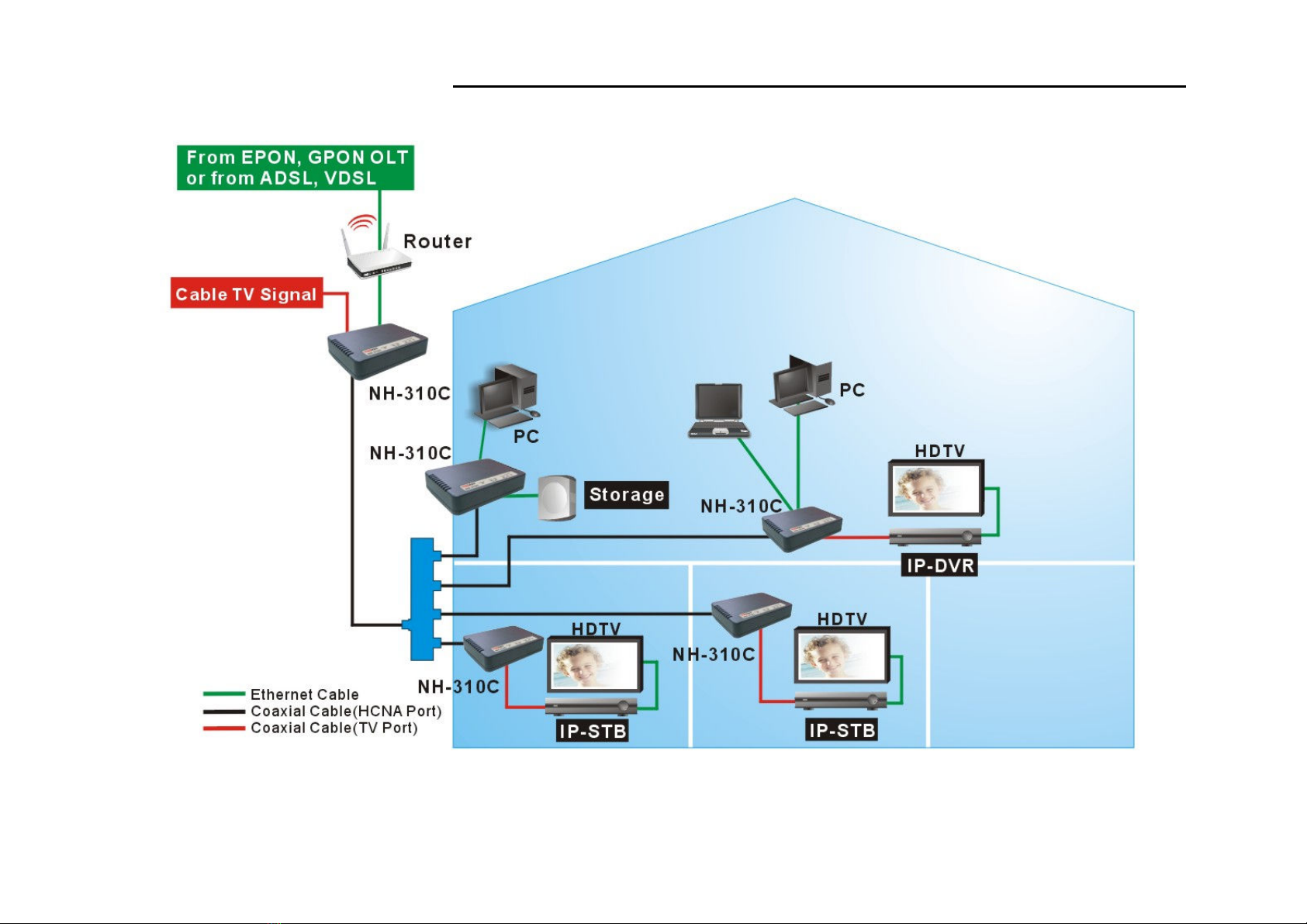
Figure 3.1: NH-310C connections diagram

NH-310C HPNA3.1 over Coaxial Cable (HCNA) End Point USER’S MANUA Ver. A7
14
Figure 3.2: NH-310C connections diagram-2

NH-310C HPNA3.1 over Coaxial Cable (HCNA) End Point USER’S MANUA Ver. A7
15
Appendix A: Cable Requirements
A CAT 3, 4 or 5 UTP (unshielded twisted pair) cable is typically used to connect the Ethernet device to the modem. A
10Base-T cable often consists of four pairs of wires, two of which are used for transmission. The connector at the end of
the 10Base-T cable is referred to as an RJ-45 connector and it consists of eight pins. The Ethernet standard uses pins 1, 2,
3 and 6 for data transmission purposes. (Table A-1)
Table A-1 RJ-45 Ethernet Connector Pin Assignments
DI DI-X
PIN #
Signal
Media Dependant
interface Signal
Media Dependant
interface-cross
1 TX+ Transmit Data + RX+ Receive Data +
2 TX- Transmit Data - RX- Receive Data -
3 RX+ Receive Data + TX+ Transmit Data +
4 -- Unused -- Unused
5 -- Unused -- Unused
6 RX- Receive Data - TX- Transmit Data -
7 -- Unused -- Unused
8 -- Unused -- Unused
Figure A-1 Standard RJ-45 repectacle/connector
Note:
Please ma e sure your connected cables are with same pin assignment as above table before deploying the cables into your
networ .

NH-310C HPNA3.1 over Coaxial Cable (HCNA) End Point USER’S MANUA Ver. A7
16
Figure A-2 Pin Assignments and Wiring for an RJ-45 Straight-Through Cable
Figure A-3 Pin Assignments and Wiring for an RJ-45 Crossover Cable

NH-310C HPNA3.1 over Coaxial Cable (HCNA) End Point USER’S MANUA Ver. A7
17
Appendix B: Product Specification
Key Features & Benefits
• Compliant with HomePNA3.1/HomePNA3.0 over coaxial cable(HCNA) specifications (ITU-T G.9954)
• Compliant with IEEE802.3 10Base-T and IEEE802.3u 100Base-Tx standards
• Compliant with IEEE802.3x flow control standard
• Provides 2 x 10/100M auto-negotiation RJ-45 Ethernet ports with auto-MDI/MDIX
• Provides 2 x f-type female coax connectors for HCNA and TV
• Supports transmission speed up to 200Mbps over coaxial cable and lin establish under -160dBm/Hz noise floor
• Supports point to point and point to multipoint application
• Supports IEEE802.1p priority mapping
• Supports IEEE802.1p/TOS priority queue
• Supports IEEE802.1Q Tag VLAN pass through
• Supports auto-speed from 32Mbps up to 200Mbps(upstream + downstream)
• Supports up to 10 endpoints or slaves
• Guaranteed QoS based on HomePNA3.1 parameterized QoS
• EMI certified by CE and FCC

NH-310C HPNA3.1 over Coaxial Cable (HCNA) End Point USER’S MANUA Ver. A7
18
Product Specification
Standards: IEEE802.3 / IEEE802.3u / ITU-T G.9954 standard
Interfaces:
2 x RJ-45, 10/100Mbps Ethernet port with Auto-MDI/MDIX
1 x F-type female coaxial connector for HCNA
1 x F-type female coaxial connector for STB/TV
1 x Power jac for 5-12VDC / 1A power adapter.
ax. Bandwidth: Up to 200Mbps
ax. Noise Floor -160dBm/Hz (Up to 1100m over RG-59 75ohm coaxial cable)
LED Indicators:
1 x Power LED
2 x Ethernet “Lin /Activity” LEDs
1 x HCNA “Lin /Activity” LED
2 x HCNA Line Speed (Quality) LED
SAT HCNA Transmission Spectrum: 12MHz ~ 44MHz
Dimensions: 130mm x 94.5mm x 27mm (5.12” x 3.72“ x 1.06“) (L x W x H)
Temperature: Operating: 0ºC ~ 50ºC (32ºF ~ 122ºF)
Storage: -20ºC ~ 70ºC (-4ºF ~ 158ºF)
Humidity: 10% ~ 90% non-condensing
External Power Adapter: 5VDC / 1A or 12VDC / 1A for commercial type adapter

NH-310C HPNA3.1 over Coaxial Cable (HCNA) End Point USER’S MANUA Ver. A7
19
Appendix C: Troubleshooting
Diagnosing the odem’s Indicators
The endpoint can be easily monitored through its comprehensive panel indicators. These indicators assist the networ
manager in identifying problems the hub may encounter. This section describes common problems you may
encounter and possible solutions.
1. Symptom: POWER indicator does not light up (green) after power on.
Cause: Defective External power supply
Solution:
Chec the power plug by plugging in another that is functioning properly. Chec the pow
er
adapter
with another device. If these measures fail to resolve the problem, have the unit power
supply replaced by a qualified distributor.
2.
Symptom: Lin indicator does not light up (green) after ma ing a connection.
Cause: Networ interface (ex. a
networ adapter card on the attached device), networ cable, or switch
port is defective.
Solution:
2.1 Verify that the endpoint and attached device are powered on.
2.2 Ma e sure the cable is plugged into both modems and corresponding device.
2.3 Verify that the proper cable type is used and its length does not exceed specified limits.
2.4 Chec the modem on the attached device and cable connections for possible defects.
2.5 Replace the defective modem or cable if necessary.
Table of contents
Other netsys Adapter manuals


