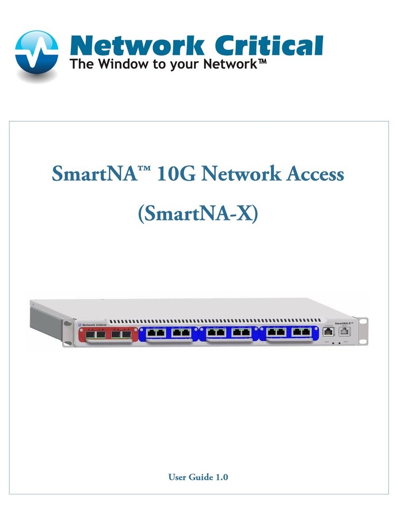
Network Critical SmartNA-X User manual

Smart Network Access Modular System X
SmartNA-X™ 1G/10G Network Tapping Device
User Guide v1.4

2 | Contents | SmartNA-X 1G/10G Modular
SmartNA-X™ 1G/10G User Guide 1.4 © 2015 Network Critical Solutions Limited
Contents
About this guide.................................................................................................................................... 9
Audience.......................................................................................................................................................................9
Conventions..................................................................................................................................................................9
Safety information....................................................................................................................................................... 9
Grounding.........................................................................................................................................................9
Power supply....................................................................................................................................................9
Servicing...........................................................................................................................................................9
Electrostatic discharge (ESD)..........................................................................................................................9
Chapter 1: Introduction..............................................................................................10
About SmartNA-X..................................................................................................................................................... 10
System features.......................................................................................................................................................... 10
SmartNA-X chassis....................................................................................................................................................11
Default settings.......................................................................................................................................................... 11
System Management..................................................................................................................................................13
Configuration options................................................................................................................................................ 13
About network TAPs.................................................................................................................................................13
Suitable locations for tapping a network.................................................................................................................. 13
TAP on individual servers.........................................................................................................................................14
TAP before a load balancer...................................................................................................................................... 14
TAP after a load balancer......................................................................................................................................... 15
TAP between internet router and firewall................................................................................................................ 16
How to set up a TAP................................................................................................................................................ 16
Chapter 2: Getting Started.........................................................................................19
List of supplied components..................................................................................................................................... 19
Installing the chassis..................................................................................................................................................19
Installing the TAP modules.......................................................................................................................................20
Cabling for administrative connections.....................................................................................................................20
Management port cabling for serial access...............................................................................................................21
Management port cabling for network access.......................................................................................................... 22
Accessing the management interfaces.......................................................................................................................22
Connecting locally using the supplied serial cable...................................................................................................22
Connecting to the system.......................................................................................................................................... 23
Connecting from a web browser...............................................................................................................................23
Connecting from a terminal client............................................................................................................................ 25
Configuring network settings.................................................................................................................................... 25
Manual network configuration.................................................................................................................................. 26
Dynamic network configuration................................................................................................................................26
Chapter 3: SmartNA-X Administration....................................................................28
Managing local users................................................................................................................................................. 28
Adding local users......................................................................................................................................... 28
Managing user accounts................................................................................................................................ 29
Managing the system time........................................................................................................................................ 30
Adding an NTP server...................................................................................................................................30
Saving the current configuration...............................................................................................................................30
Loading a configuration............................................................................................................................................ 31

SmartNA-X 1G/10G Modular | Contents | 3
SmartNA-X™ 1G/10G User Guide 1.4 © 2015 Network Critical Solutions Limited
Using the CLI to restore a configuration......................................................................................................31
Downloading the system configuration.....................................................................................................................31
Uploading a system configuration.............................................................................................................................32
Upgrade system firmware..........................................................................................................................................32
To upgrade the system firmware...................................................................................................................32
Installing Feature Packs.............................................................................................................................................33
Installing a Feature Pack............................................................................................................................... 33
Configuring system security......................................................................................................................................34
Managing public host keys............................................................................................................................34
Configuring management access................................................................................................................... 35
Configuring TACACS+ authentication servers.............................................................................................36
Configuring RADIUS authentication servers................................................................................................38
Managing transaction logging....................................................................................................................... 39
Rebooting the system................................................................................................................................................ 41
Reboot the system..........................................................................................................................................41
Chapter 4: Configuring Ports.................................................................................... 42
Configuring Ports.......................................................................................................................................................42
Working with copper ports............................................................................................................................42
Configuring port settings...............................................................................................................................44
Viewing port statistics................................................................................................................................... 46
Chapter 5: Moving Traffic With Maps.....................................................................48
Creating maps in the web UI....................................................................................................................................48
Chapter 6: Restricting Traffic with Filters...............................................................50
Using filters................................................................................................................................................................50
Defining filters........................................................................................................................................................... 50
Packet header filtering criteria.................................................................................................................................. 51
Defining custom fields.............................................................................................................................................. 55
Applying filtering...................................................................................................................................................... 56
Chapter 7: Load Balancing........................................................................................ 57
Load balancing...........................................................................................................................................................57
Load balancing on SmartNA-X.....................................................................................................................57
Load balancing – Best practices and limitations.......................................................................................... 58
Setting up load balancing.......................................................................................................................................... 58
Chapter 8: Working with the V-Line Module..........................................................61
About V-Line modules.............................................................................................................................................. 61
V-Line module functionality..................................................................................................................................... 61
V-Line mode.................................................................................................................................................. 61
Breakout mode............................................................................................................................................... 62
Aggregation mode..........................................................................................................................................63
Egress mode................................................................................................................................................... 63
Configuring the V-Line operational mode................................................................................................................64
Configure V-Line mode................................................................................................................................ 64
Configure Breakout mode............................................................................................................................. 65
Configure Aggregation mode........................................................................................................................ 66
Configure Egress mode................................................................................................................................. 67

4 | Contents | SmartNA-X 1G/10G Modular
SmartNA-X™ 1G/10G User Guide 1.4 © 2015 Network Critical Solutions Limited
Chapter 9: Working with the Intelligent Packet Processor (IPP) Module.............69
Physical...................................................................................................................................................................... 69
Overview of the IPP operation..................................................................................................................................69
Detailed operation of the IPP module.......................................................................................................................69
Matches.......................................................................................................................................................... 69
Actions........................................................................................................................................................... 70
Transforms..................................................................................................................................................... 70
Packet slicing................................................................................................................................................. 71
Committing changes after configuring the IPP module................................................................................71
Configuring the IPP module......................................................................................................................................72
Example Transforms..................................................................................................................................................74
Chapter 10: SNMP...................................................................................................... 76
Enabling SNMP......................................................................................................................................................... 76
SNMP versions and workflow.................................................................................................................................. 76
SNMP v1 and v2...........................................................................................................................................76
SNMP v3........................................................................................................................................................76
SNMP workflow............................................................................................................................................ 77
SNMP Engine ID.......................................................................................................................................................77
Defining notification (trap) settings.......................................................................................................................... 78
Specifying send notifications.........................................................................................................................78
Configuring notification hosts....................................................................................................................... 79
Defining SNMPv1/v2 communities.......................................................................................................................... 79
Define SNMPv1/v2 communities..................................................................................................................80
Configuring SNMP v3...............................................................................................................................................80
Defining SNMP users....................................................................................................................................81
Mapping SNMPv1/v2 users to SecurityNames.............................................................................................82
Creating SNMP groups..................................................................................................................................83
Defining SNMP views...................................................................................................................................84
Defining the group access policy..................................................................................................................85
Chapter 11: Command Line Reference.................................................................... 87
CLI notation............................................................................................................................................................... 87
CLI editing and command completion..................................................................................................................... 87
General CLI commands.............................................................................................................................................88
Help................................................................................................................................................................ 88
commit............................................................................................................................................................89
create settings.................................................................................................................................................90
restore............................................................................................................................................................. 90
delete settings.................................................................................................................................................90
reboot..............................................................................................................................................................91
set timeout......................................................................................................................................................91
exit..................................................................................................................................................................92
System name, contact and location........................................................................................................................... 93
show system................................................................................................................................................... 93
show name..................................................................................................................................................... 93
set name......................................................................................................................................................... 94
show location................................................................................................................................................. 94
set location..................................................................................................................................................... 94
show contact.................................................................................................................................................. 95
set contact...................................................................................................................................................... 95
set banner....................................................................................................................................................... 95

SmartNA-X 1G/10G Modular | Contents | 5
SmartNA-X™ 1G/10G User Guide 1.4 © 2015 Network Critical Solutions Limited
show banner................................................................................................................................................... 96
Network configuration commands............................................................................................................................ 97
show ntp.........................................................................................................................................................97
create ntp........................................................................................................................................................97
delete ntp........................................................................................................................................................97
show ipv4....................................................................................................................................................... 98
set ipv4 static................................................................................................................................................. 98
set ipv4 gateway............................................................................................................................................ 98
set ipv4 dns....................................................................................................................................................99
set ipv4 dhcp..................................................................................................................................................99
show ipv6..................................................................................................................................................... 100
set ipv6 static............................................................................................................................................... 100
set ipv6 gateway.......................................................................................................................................... 101
Local users commands............................................................................................................................................ 102
show users....................................................................................................................................................102
create user.................................................................................................................................................... 102
delete user.................................................................................................................................................... 103
set user level................................................................................................................................................ 103
set user password.........................................................................................................................................103
Authentication and accounting services commands................................................................................................105
set authentication......................................................................................................................................... 105
show radius.................................................................................................................................................. 105
create radius authserver............................................................................................................................... 105
delete radius authserver............................................................................................................................... 106
create radius accserver.................................................................................................................................106
delete radius accserver.................................................................................................................................107
show tacacs.................................................................................................................................................. 107
create tacacs authserver............................................................................................................................... 107
delete tacacs authserver............................................................................................................................... 108
create tacacs accserver.................................................................................................................................108
delete tacacs accserver.................................................................................................................................109
set log...........................................................................................................................................................109
Module commands...................................................................................................................................................110
select.............................................................................................................................................................110
show status................................................................................................................................................... 110
show counters.............................................................................................................................................. 111
clear counters............................................................................................................................................... 111
show temperaturehigh..................................................................................................................................111
set temperaturehigh......................................................................................................................................112
show rates.................................................................................................................................................... 112
show errors...................................................................................................................................................112
Port settings commands...........................................................................................................................................114
show port......................................................................................................................................................114
set port autolock.......................................................................................................................................... 115
set port autoneg........................................................................................................................................... 115
set port name/description.............................................................................................................................116
set port duplex............................................................................................................................................. 117
set port lock................................................................................................................................................. 117
set port mastering........................................................................................................................................ 118
set port mdi..................................................................................................................................................118
set port name............................................................................................................................................... 119
set port speed............................................................................................................................................... 120
set port tap................................................................................................................................................... 120
set port traffichigh....................................................................................................................................... 121
set port trafficlow........................................................................................................................................ 121
set port usage............................................................................................................................................... 122

6 | Contents | SmartNA-X 1G/10G Modular
SmartNA-X™ 1G/10G User Guide 1.4 © 2015 Network Critical Solutions Limited
Port mapping commands......................................................................................................................................... 123
show maps....................................................................................................................................................123
set map......................................................................................................................................................... 123
delete map.................................................................................................................................................... 125
clear maps.................................................................................................................................................... 126
Filtering and load balancing commands................................................................................................................. 127
set filter any................................................................................................................................................. 127
set filter anyip..............................................................................................................................................128
set filter ipv4................................................................................................................................................130
set filter ipv6................................................................................................................................................133
set filter arp..................................................................................................................................................136
set filter mpls............................................................................................................................................... 137
set customfield............................................................................................................................................. 138
set lbheaders.................................................................................................................................................139
delete filter................................................................................................................................................... 140
delete customfield........................................................................................................................................ 141
show filters...................................................................................................................................................141
show customfields........................................................................................................................................141
show lbheaders.............................................................................................................................................142
SNMP commands.................................................................................................................................................... 143
snmp show agent......................................................................................................................................... 143
snmp enable agent....................................................................................................................................... 143
snmp disable agent...................................................................................................................................... 143
snmp show all..............................................................................................................................................144
snmp show engineid.................................................................................................................................... 145
snmp apply................................................................................................................................................... 145
snmp show notify........................................................................................................................................ 145
snmp enable notify...................................................................................................................................... 146
snmp disable notify......................................................................................................................................146
snmp show host........................................................................................................................................... 147
snmp create host.......................................................................................................................................... 148
snmp delete host.......................................................................................................................................... 148
snmp show community................................................................................................................................149
snmp create community...............................................................................................................................149
snmp delete community...............................................................................................................................150
snmp show user........................................................................................................................................... 150
snmp create user.......................................................................................................................................... 151
snmp delete user.......................................................................................................................................... 152
snmp show sectogroup................................................................................................................................ 152
snmp create sectogroup............................................................................................................................... 153
snmp delete sectogroup............................................................................................................................... 154
snmp show view.......................................................................................................................................... 154
snmp create view......................................................................................................................................... 155
snmp delete view......................................................................................................................................... 156
snmp show access........................................................................................................................................156
snmp create access.......................................................................................................................................157
snmp delete access.......................................................................................................................................157
snmp show comtosec...................................................................................................................................158
snmp create comtosec..................................................................................................................................158
snmp delete comtosec..................................................................................................................................159
V-Line module commands...................................................................................................................................... 160
show vline.................................................................................................................................................... 160
set vline mode..............................................................................................................................................160
set vline bypass............................................................................................................................................161
set vline heartbeat rate.................................................................................................................................162
set vline heartbeat timeout.......................................................................................................................... 162

SmartNA-X 1G/10G Modular | Contents | 7
SmartNA-X™ 1G/10G User Guide 1.4 © 2015 Network Critical Solutions Limited
set vline heartbeat packet............................................................................................................................ 163
set vline slicing............................................................................................................................................163
set vline breakout.........................................................................................................................................164
set vline aggregate....................................................................................................................................... 165
set vline inject..............................................................................................................................................165
Intelligent Packet Processor (IPP) Card Module Commands................................................................................. 167
create packetprocessor transform................................................................................................................ 167
delete packetprocessor transform................................................................................................................ 167
show packetprocessor transform................................................................................................................. 167
show packetprocessor transforms................................................................................................................168
show packetprocessor matches....................................................................................................................169
set packetprocessor transform match.......................................................................................................... 171
set packetprocessor transform named-match...............................................................................................172
set packetprocessor transform clear match................................................................................................. 173
set packetprocessor transform clear named-match......................................................................................173
set packetprocessor transform action.......................................................................................................... 174
set packetprocessor speed............................................................................................................................175
show packetprocessor speed........................................................................................................................175
set port packetprocessor transform..............................................................................................................176
set port packetprocessor clear transform.....................................................................................................176
set port packetprocessor slicing...................................................................................................................177
cancel packetprocessor.................................................................................................................................177
Chapter 12: Troubleshooting................................................................................... 178
Troubleshooting network issues.............................................................................................................................. 178
Connecting to the IPv6 link local address.................................................................................................. 178
Troubleshooting slow transmission rates (copper ports)........................................................................................ 179
Troubleshooting Java plugins..................................................................................................................................179
Troubleshooting the CLI......................................................................................................................................... 180
Troubleshooting SNMP........................................................................................................................................... 181
Troubleshooting the web UI....................................................................................................................................182
Appendix A: Physical and electrical specifications................................................ 183
Appendix B: V-Line Module Specifications............................................................185
V-Line module operating specifications................................................................................................................. 185
V-Line module data interfaces................................................................................................................................ 185
Live ports (A & B)......................................................................................................................................186
TAP ports (C & D)..................................................................................................................................... 186
V-Line Module LED Indicators.............................................................................................................................. 187
Port LED Status Indicators..........................................................................................................................187
Bypass LED status indicators......................................................................................................................187
Appendix C: Intelligent Packet Processor (IPP) Module Specifications.............. 189
IPP module operating specifications....................................................................................................................... 189
IPP module data interfaces......................................................................................................................................189
IPP Module front panel........................................................................................................................................... 190
Appendix D: IPP Module Preset Matches and Transforms..................................191
Preset Ethertype Matches........................................................................................................................................ 191
IP header matches....................................................................................................................................................192

8 | Contents | SmartNA-X 1G/10G Modular
SmartNA-X™ 1G/10G User Guide 1.4 © 2015 Network Critical Solutions Limited
Transport header Matches....................................................................................................................................... 193
GRE header matches............................................................................................................................................... 194
Layer above TCP/UDP............................................................................................................................................195
IPP module preset Transforms................................................................................................................................ 196
Appendix E: Supported MIBs..................................................................................198
Hardware warranty.......................................................................................................................... 199
Contacting Network Critical............................................................................................................200

SmartNA-X™ 1G/10G User Guide 1.4 © 2015 Network Critical Solutions Limited
About this guide
Audience
The guide is intended for use by network administrators who are responsible for operating and maintaining network
equipment. Consequently, this manual assumes a basic working knowledge of general switch functions, the Internet
Protocol (IP), and Simple Network Management Protocol (SNMP).
Conventions
The following conventions are used throughout this guide to show information:
Note: Emphasizes important information or calls your attention to related features or instructions.
Caution: Alerts you to a potential hazard that could cause loss of data, or damage the system or equipment.
Safety information
Grounding
There must be an interruptible safety earth ground from the main power source to the product’s input wiring terminals,
power cord, or supplied power cord set. Whenever it is likely that protection has been impaired, disconnect the power cord
until the ground has been restored.
Power supply
Removable power supplies are to be used in the SmartNA-Xsystem only. For pluggable equipment the socket outlet shall
be installed near the equipment and shall be easily accessible.
Servicing
There are no user-serviceable parts inside this product. Any servicing, adjustment, maintenance or repair must be
performed only by service-trained personnel.
Electrostatic discharge (ESD)
Electrostatic discharge can damage electrical components. SmartNA-X components are wrapped in antistatic bags to
prevent this damage. Before handling SmartNA-X components, attach an antistatic wrist strap to a grounded metal surface
to prevent electrostatic discharge from damaging your hardware. If you do not have a wrist strap, just prior to removing
the product from ESD packaging and installing or replacing hardware, touch an unpainted metal surface for a minimum of
5 seconds.

10 | Introduction | SmartNA-X 1G/10G Modular
SmartNA-X™ 1G/10G User Guide 1.4 © 2015 Network Critical Solutions Limited
Chapter 1
Introduction
About SmartNA-X
SmartNA-X provides a modular, scalable and customizable 1/10G packet broker and TAP solution for network
monitoring and security tools.
The SmartNA-X system is designed to work as an enterprise solution custom fit for any data centre, no matter the size. It
has advanced packet filtering capabilities and flexible port maps and is able to filter 10G traffic to 1G tools, or aggregate
1G links to a 10G tool.
System features include:
• Independently operating, hot-swappable TAP modules available in a range of port media configurations.
• Failsafe copper ports that continue to operate when the system loses power.
• Flexible port maps for aggregation and replication of traffic to any port.
• Advanced packet filtering capabilities based on packet EtherType.
• Integrated web and CLI agents for browser and command line management access.
• Patented Drag-n-Vu™ technology for easy set up of port mapping, filtering and port monitoring.
• Optional V-Line (Bypass) TAP modules for inline integration of network tools.
• Packet slicing options.
• Support for RADIUS/TACAS+ authentication and accounting servers.
• Integrated SNMPv3 management agent.
• Optional chassis dual power units.
System features
SmartNA-X provides a modular, scalable and customizable 1/10G packet broker and TAP solution for network
monitoring and security tools. It is designed to work as an enterprise solution custom fit for any data center, no matter
the size. It has advanced packet filtering capabilities and flexible port maps, and is able to filter 10G traffic to 1G tools or
aggregate 1G links to a 10G port.
Key features of the system include:
• Support for both command line and web browser management interfaces. The web interface provides the patented
Drag-n-Vu™ user interface for fully configurable, filtering, port mapping and improved monitoring flexibility
• Load Balancing, 9-tuple
• V-Line (Bypass) TAP Modules
• Packet Slicing
• VLAN Tagging
• Local or external authentication and authorization via RADIUS and TACAS+
• Hot-swappable TAP modules that allow continuous monitoring even while they are being switched
• Fail-safe ports that will permit data traffic to flow even after a TAP failure
• Dual independent power connectors
• Advanced packet filtering
• Three user access levels: Administrator user, Standard user, Audit user

SmartNA-X 1G/10G Modular | Introduction | 11
SmartNA-X™ 1G/10G User Guide 1.4 © 2015 Network Critical Solutions Limited
• Stacking
Feature Packs
In addition to the above standard features, Feature Packs can be installed to add filtering and load balancing on a per-port
basis. Each Feature Pack adds the advertised capabilities to a set of twelve (floating) ports.
See Installing a Feature Pack on page 33 for information about adding a Feature Pack.
SmartNA-X chassis
The SmartNA-X chassis supports four independently operating, hot-swappable TAP modules, and provides two 10G bps
ports at the rear. Each module has four ports that operate in pairs for connecting to a live network and network monitoring
tools. Slot 1 (on the left of the chassis) supports data rates up to 10G bps, while Slots 2–4 support data rates up to 1G
bps. The chassis also provides network and serial management ports for remote and local connections to the web and CLI
management interfaces.
Figure 1: Chassis front
At the rear of the device are additional 10 Gbps ports and either one or two swappable power supply units (PSUs), as
shown in the following diagram. The second PSU is optional, but is recommended as a safeguard against single-point
power failures.
Figure 2: Chassis rear
Default settings
List of default settings for SmartNA-X.

12 | Introduction | SmartNA-X 1G/10G Modular
SmartNA-X™ 1G/10G User Guide 1.4 © 2015 Network Critical Solutions Limited
Table 1: SmartNA-X default settings
Function Default settings
Console port connection • Baud Rate: 9600 bps
• Data bits: 8
• Stop bits: 1
• Parity: None
IPv4 settings • IPv4 address: 192.168.254.100
• Subnet: 255.255.255.0
• Gateway: None
• DNS server: None
IPv6 settings • IPv6 link local address: Automatic
• IPv6 address: None
• IPv6 prefix length: None
• IPv6 gateway: None
Web management • HTTP Secure Server: Enabled
• HTTP Secure Server Port: 443
• Web management Timeout: 1 minute for an incorrectly
ended session (browser closed without logging out or a
dropped connection)
SNMP • SNMP Agent: Disabled
• Community strings: None configured
User accounts •Auditor
• Permissions: Read only
• Username: audit
• Password: audit
•Operator
• Permissions: Read-write access to port and module
settings. Read-only access to system-wide settings.
• Username: user
• Password: user
•Administrator
• Permissions: Read-write access to all port, module
and system-wide settings.
• Username: admin
• Password: admin
Idle timeout 15 minutes

SmartNA-X 1G/10G Modular | Introduction | 13
SmartNA-X™ 1G/10G User Guide 1.4 © 2015 Network Critical Solutions Limited
System Management
SmartNA-X can be managed from a web browser or from a command line interface (CLI). System management can
be performed using a Java enabled web browser, using a terminal client over SSH, or by a direct serial connection to a
terminal or a PC running terminal emulator software.
Configuration options
The SmartNA-X system contains an integrated HTTP web agent that allows you to configure system settings in an
intuitive, graphical user-interface using a web browser from any remotely connected computer. The system also contains a
command line interface that lets you configure the system using SmartNA-X commands, either remotely or direct from a
PC connected serially.
In addition to the web and CLI interfaces, SmartNA-X contains an SNMP agent that allows the system to be managed
from SNMP stations, and SNMP hosts to receive notifications when alerts requiring administrator assistance occur.
Using the integrated management interfaces, you can:
• Display system information and port statistics.
• Configure the network interface.
• Administer local users.
• Change port settings and set up port maps.
• Add RADIUS/TACACS+ servers for centralized authentication and accounting.
• Add packet filters to maps.
• Set up load balancing groups (supported systems only).
• Update system firmware.
• Configure SNMPv1/v2c/v3 management stations and enable SNMP notifications.
About network TAPs
A network TAP provides a means of unobtrusively connecting to a data network for the purpose of accessing the traffic
(data packets) flowing along that network and sending it to network tools.
Packets entering the TAP can be analysed, blocked, reformatted, or saved to disk, depending on the functionality of the
network tool.
A TAP consists of at least three ports:
• Two data ports that are connected to the upstream and downstream links of a live network.
• One monitor port that is connected to a network tool.
TAPs are commonly used for network intrusion detection systems, VoIP recording, network probes, RMON probes,
packet sniffers, and other monitoring and collection devices and software that require access to a network segment. And
are often deployed on critical network paths where data needs to be continuously monitored. With advanced network TAP
devices like those from Network Critical, 10G sections can be tapped and filtered so existing 1G tools can be used.
Suitable locations for tapping a network
Selecting a suitable network location and scheduling a maintenance window is crucial if you want to avoid missing vital
packets and disrupting the network while you set up the TAP.
There are many places where you can place a network TAP, including:

14 | Introduction | SmartNA-X 1G/10G Modular
SmartNA-X™ 1G/10G User Guide 1.4 © 2015 Network Critical Solutions Limited
• On individual servers
• Before a load balancer
• After a load balancer
• Between an Internet router and a firewall
TAP on individual servers
You can place TAPs on individual servers for greater control when scheduling network outages, since there is no need to
take down all servers while the TAP is being deployed.
The following figure shows a configuration with three servers and three TAPs, one for each server. Each TAP is
connected to the AB ports of a SmartNA-X module (one module per server). If necessary, the resulting traffic streams can
be aggregated before sending to a network tool. A fully populated SmartNA-X device with four modules installed allows
up to four servers to be tapped (or more if C&D ports are used in TAP/failsafe mode).
Figure 3: TAPs placed on individual servers
TAP before a load balancer
You can place TAPs before a load balancer to monitor a group of servers with one TAP. In this location, you'll be able to
observe the IP addresses of individual requesters and have a better understanding of user traffic locations.
Note: Care must be taken when scheduling the TAP deployment, since all the servers on the segment will be
taken offline while the TAP is connected and configured.
A limitation of placing TAPs before a load balancer is that the balancer's IP address may take on the appearance of the
server providing the response to the requested information. If your preference is to follow which servers are responding to
the users request, you should place the TAP after the load balancer.
The following figure shows a configuration where a TAP is placed before a load balancer.

SmartNA-X 1G/10G Modular | Introduction | 15
SmartNA-X™ 1G/10G User Guide 1.4 © 2015 Network Critical Solutions Limited
Figure 4: TAP configuration before a load balancer
TAP after a load balancer
You can place TAPs after a load balancer to monitor a group of servers with a single TAP. In this location, you'll be able
to observe which servers are responding to the requested information.
Note: Care must be taken when scheduling the TAP deployment, since all the servers on the segment will be
taken offline while the TAP is connected and configured.
A limitation of placing TAPs after a load balancer would be understanding who is requesting the information. The Load
Balancer typically will appear as the user address making the requester of data appear as a single user. Another possibility
to address recognizing a users location depends on the type of load balancer you are using. For example, if your load
balancer supports it you can enable “x-forward-for” so that the user IP is included in the packet information. Other
possibilities include instrumenting requester information into a custom field embedded in the application. Both methods
are common when monitoring user traffic.
The following figure shows a configuration where a TAP is placed after a load balancer.

16 | Introduction | SmartNA-X 1G/10G Modular
SmartNA-X™ 1G/10G User Guide 1.4 © 2015 Network Critical Solutions Limited
Figure 5: TAP configuration before a load balancer
TAP between internet router and firewall
You can place a TAP between an internet router and a firewall to monitor the data exchanged between the public Internet
and your local Intranet.
Figure 6: TAP configuration between router and firewall
How to set up a TAP
You set up a TAP by connecting the SmartNA-X to your LAN and directing the received traffic to your network
monitoring tools for capture or analysis. Once the TAP has been installed its presence is transparent to traffic flowing
along that segment.

SmartNA-X 1G/10G Modular | Introduction | 17
SmartNA-X™ 1G/10G User Guide 1.4 © 2015 Network Critical Solutions Limited
1. Connect your live network to TAP ports A and B. If you are connecting to a 10G network, you must connect to the AB
ports of a 10G module fitted in slot 1 of the chassis. If connecting to a 1G network, you may use any of the AB ports,
including those in slot 1.
Verify that the LED link lights are on. If there is no link, you may need to reconfigure the port comm settings. See the
relevant step below.
2. Map ports A and B to each other to join the live links and allow traffic to flow across the TAP.
Figure 7: Map A and B ports to join the live links
Assuming module 3, the equivalent CLI commands are:
CONTROLLER>set map 3a to 3b
CONTROLLER>set map 3b to 3a
3. Map the live ports to output ports C and/or D as required.
Figure 8: Map A and B ports to C and/or D output ports
The equivalent CLI commands are as follows:
CONTROLLER>set map 3a to 3c
CONTROLLER>set map 3b to 3c
4. Configure port usage and for copper ports, communication settings. In most cases, copper port settings can be left at
Auto, in which case the linked ports will negotiate the optimum settings themselves.

18 | Introduction | SmartNA-X 1G/10G Modular
SmartNA-X™ 1G/10G User Guide 1.4 © 2015 Network Critical Solutions Limited
Figure 9: Configure port settings
The equivalent CLI commands for port 3A shown in the above figure are as follows:
CONTROLLER>select slot 3
SLOT3>set port A usage network
SLOT3>set port A autoneg
SLOT3>set port A mdi auto
SLOT3>set port A speed auto
SLOT3>set port A duplex auto
SLOT3>set port A mastering preferMaster
SLOT3>set port A tap LFP
5. If required, define and apply filters to limit the packets sent to the output ports to a subset of the overall data stream.
Figure 10: Apply filters
The equivalent CLI commands for the filters shown in the above figure are as follows:
SLOT3>set map 3a to 3c require HTTP
SLOT3>set map 3b to 3d exclude HTTP
6. Connect your network tool(s) to port C and/or D depending on whether you want to analyse data on the upstream or
downstream links, or both.

SmartNA-X™ 1G/10G User Guide 1.4 © 2015 Network Critical Solutions Limited
Chapter 2
Getting Started
List of supplied components
The following components have been supplied with your SmartNA-X system.
• SmartNA-X 1U chassis.
• SmartNA-X TAP modules (models as per your order). Red modules are maximum 10 gigabit/second (10G bps), blue
modules are maximum 1 gigabit/second (1G bps).
• 10G optical cables.
• Serial management cable – DE-9 female to 8P8C (1.5 meters).
• SmartNA-X chassis rack ears (brackets and screws).
• 2 x power leads.
• Blanking plates to cover empty slots when running.
Please contact Network Critical Support ([email protected]) if any item is missing from the package.
Installing the chassis
To prevent unregulated access, the SmartNA-X chassis should be installed in a secure server rack with access to
authorized personnel only.
Caution: Static electricity can damage sensitive electronic components. To discharge static, fit an antistatic wrist-
strap or touch a bare metal surface before handling SmartNA-X components.
1. Unpack all parts onto a clean workbench for inspection.
2. Carefully check all parts against your order. If any parts are missing or have become damaged during shipping, please
report it immediately to Network Critical. See Contacting Network Critical on page 200 for contact information.
3. Attach the rack ears to the sides of the chassis using the supplied screws.
Figure 11: Attach the rack ears to the SmartNA-X chassis
4. Install the chassis in a 19" server rack. The chassis occupies one rack unit. Be sure to leave enough room for all the
cable connections (front and back), and for proper airflow and ventilation around the chassis.

20 | Getting Started | SmartNA-X 1G/10G Modular
SmartNA-X™ 1G/10G User Guide 1.4 © 2015 Network Critical Solutions Limited
5. Depending on whether your chassis is AC or DC powered, plug the chassis into an AC (100V-240V) or a DC (-42V to
-63V) supply. If your chassis has dual power sockets, make sure they are connected to independent supplies to ensure
the chassis is able to remain powered should either suffer a power cut.
6. Turn on the chassis power switch(es) to start the system. Management interfaces will be available within two minutes,
but data ports will immediately begin to pass traffic.
7. Connect management cables to the management ports, as described in Cabling for administrative connections on page
20.
Installing the TAP modules
TAP modules are hot-swappable and can be installed and removed while the chassis is powered up without affecting other
modules. Red 10G bps modules must only be installed in the left-most slot (Slot 1). Blue 1G bps modules may be installed
in any slot (Slots 1–4).
1. Wear an anti-static wrist strap or take other precautions against electrostatic discharge (ESD) before handling the TAP
modules.
2. Remove the TAP modules from their ESD bags. The modules are colour-coded as follows:
• Red – 10G bps maximum. Red modules must only be used in Slot 1 (left-most slot).
• Blue – 1G bps maximum. Blue modules may be used in any slot.
The following figure shows the correct placement of the 10G and 1G modules:
3. Carefully slide the TAP modules into the chassis slots until they are fully inserted and flush with the chassis face. You
should feel a slight resistance as the module engages with contacts in the chassis. Note that red modules can only be
used in Slot 1, as shown in the figure below.
Figure 12: Install red 10G Modules in Slot 1 only
4. Fit the supplied blanking plates to any remaining empty slots. This is to ensure correct cooling of the chassis during
operation.
Cabling for administrative connections
SmartNA-X provides dual administration ports for networked or serial access to the management interfaces. In most
cases, users will connect to the system remotely over a network. When first setting up, you may need to use the
CONSOLE in order to configure the network interface address.
SmartNA-X provides the following administration ports:
Other manuals for SmartNA-X
1
Table of contents
Other Network Critical Network Hardware manuals
Popular Network Hardware manuals by other brands

Black Box
Black Box Palm-Sized Ethernet Switch Express 8-Port... Specifications

Multitech
Multitech RouteFinder RF850 Brochure & specs

HIK VISION
HIK VISION 7600NI-SE Series user manual

HIK VISION
HIK VISION DS-7600NXI-K1 Series user manual

Black Box
Black Box RF200A manual

seeed studio
seeed studio C Series quick start guide