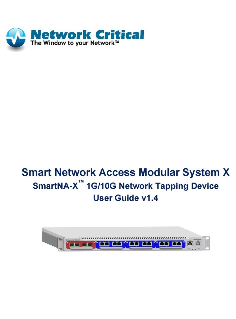
Network Critical SmartNA-X User manual

SmartNA™ 10G Network Access
(SmartNA-X)
User Guide 1.0

i
DRAFT
SMARTNA-X
CONTENTS
Preface...............................................................................................................................1
Symbols used in the documentation .......................................................................................... 1
Safety information ................................................................................................................... 1
Grounding..............................................................................................................................................1
Power supply ..........................................................................................................................................1
Servicing .................................................................................................................................................1
Command line notation ...........................................................................................................2
Chapter 1 – Overview ...........................................................................................................3
SmartNA-X features ................................................................................................................. 3
Hardware overview .................................................................................................................. 3
Managing SmartNA-X..............................................................................................................5
Managing SmartNA-X through the web UI............................................................................................5
Managing SmartNA-X through the CLI .................................................................................................8
Chapter 2 – Introduction to network TAPs .......................................................................... 10
What is a network TAP? ......................................................................................................... 10
Suitable locations for placing TAPs ......................................................................................... 11
Placing TAPs on individual servers .......................................................................................................11
Placing TAPs on multiple servers ..........................................................................................................12
Placing TAPs on multiple locations ......................................................................................................12
Chapter 3 – Setting up SmartNA-X ..................................................................................... 14
Check items included............................................................................................................. 14
Installing the SmartNA-X chassis and TAP modules ................................................................. 14
Powering up the system ..........................................................................................................15
Connecting to the Management/Network port......................................................................... 16
Logging in to SmartNA-X ...................................................................................................... 16
Chapter 4 – Administering SmartNA-X ............................................................................... 21
Logging in............................................................................................................................. 21
Configuring SmartNA-X for the first time............................................................................... 23
Configuring network settings ................................................................................................. 24

ii
SMARTNA™ 10G NETWORK ACCESS (SMARTNA-X)
CONTENTS |
DRAFT
Enabling NTP ....................................................................................................................... 25
Managing user accounts and authentication............................................................................. 26
Authenticating users.............................................................................................................................. 26
Enabling RADIUS and TACACS+ authentication servers .................................................................... 27
Enabling transaction logging .................................................................................................. 29
Saving and restoring SmartNA-X configurations ...................................................................... 30
Restoring default settings and custom configurations............................................................................31
Downloading and uploading a configuration ........................................................................................31
Rebooting the system ............................................................................................................. 32
Updating system firmware ...................................................................................................... 32
Uploading a user-defined SSL certificate ................................................................................. 33
Changing your password ........................................................................................................ 33
Monitoring system health....................................................................................................... 34
Chapter 5 – Using the Web User Interface ........................................................................... 35
Accessing the web UI ............................................................................................................. 35
Selecting options in the system diagram .................................................................................. 36
Port speed indicator ............................................................................................................... 36
Further information..............................................................................................................................37
Chapter 6 – Configuring ports ............................................................................................ 38
Configuring port communication settings ............................................................................... 38
Avoiding duplex mismatching...............................................................................................................38
Configuring port failsafe and LFP (TAP mode)........................................................................ 40
Testing failsafe ......................................................................................................................................41
Configuring ports roles .......................................................................................................... 42
Configuring port traffic thresholds ......................................................................................... 43
Configuring port locking ....................................................................................................... 44
Saving port settings................................................................................................................ 45
Chapter 7 – Creating Port Maps ......................................................................................... 47
About port maps.................................................................................................................... 47
Creating port maps ................................................................................................................ 49
Creating maps in the web UI ................................................................................................................50
Creating port maps in the CLI..............................................................................................................52
Typical map configurations .................................................................................................... 52
Breakout TAP.......................................................................................................................................52
Aggregation TAPs.................................................................................................................................52
Regeneration TAPs ...............................................................................................................................52
Chapter 8 – Using Packet Filters ......................................................................................... 54
About packet filters................................................................................................................ 54
How packet filters work ........................................................................................................................54
Creating packet filters ............................................................................................................ 55

iii
SMARTNA™ 10G NETWORK ACCESS (SMARTNA-X)
CONTENTS |
DRAFT
Adding filters to maps ............................................................................................................ 56
Chapter 9 – Using SNMP ................................................................................................... 58
About SNMP and SmartNA-X................................................................................................ 58
About VACM ........................................................................................................................ 60
Configuring SNMP ............................................................................................................... 61
SNMP default configuration.................................................................................................................61
Enabling SNMP ...................................................................................................................................61
SNMP engine ID..................................................................................................................................62
Configuring SNMP notifications..........................................................................................................62
Configuring SNMPv1/v2c communities...............................................................................................63
Configuring trap managers (notification hosts) ..................................................................................... 64
Configuring SNMPv3 users with VACM .............................................................................................65
Adding a member or security name to a group......................................................................................66
Configuring views.................................................................................................................................67
Configuring the access control list.........................................................................................................68
Appendix A Command Line Interface Reference............................................................................... 69
Basic commands ..........................................................................................................................................70
Commands for managing contact and location details .................................................................................79
Commands for managing network configuration.........................................................................................83
Commands for managing users....................................................................................................................94
Commands for managing authentication and accounting ..........................................................................100
Commands for managing TAP modules ....................................................................................................113
Commands for managing TAP ports .........................................................................................................114
Commands for managing port maps and packet filters ..............................................................................133
Commands for managing SNMP ..............................................................................................................152
Appendix B Web User-Interface Reference ..................................................................................... 189
System identity tab ...............................................................................................................190
Mapping tab.........................................................................................................................191
Filters tab.............................................................................................................................192
SNMP tab ............................................................................................................................195
Security tab ..........................................................................................................................199
Health tab ............................................................................................................................200
Management tab ...................................................................................................................202
TAP module health tab .........................................................................................................203
Port tab................................................................................................................................204
Port Traffic tab .....................................................................................................................206
Port Errors tab......................................................................................................................206
Port health tab......................................................................................................................207
Appendix C Specifications.............................................................................................................. 209

iv
SMARTNA™ 10G NETWORK ACCESS (SMARTNA-X)
CONTENTS |
DRAFT
SmartNA-X chassis ...............................................................................................................209
10 Gbit/s TAP module (SFP+ & SFP) ....................................................................................210
1 Gbit/s TAP module (RJ45 & RJ45).....................................................................................211
1 Gbit/s TAP module (LC & RJ45) .......................................................................................212
1 Gbit/s TAP module (RJ45 & SFP) ......................................................................................212
1 Gbit/s TAP module (LC & SFP) .........................................................................................213
Appendix D Troubleshooting......................................................................................................... 214
Troubleshooting connections to SmartNA-X...........................................................................214
Problems with slow data throughput on copper (RJ) ports..................................................................214
Connecting with IPv6.........................................................................................................................214
Troubleshooting the web UI ..................................................................................................216
Resolving web UI issues on Mac OSX.................................................................................................216
Troubleshooting the CLI .......................................................................................................217
Troubleshooting SNMP.........................................................................................................218
Resetting the system to the default configuration ....................................................................218
Appendix E Glossary ...................................................................................................................... 219
Appendix F Hardware Warranty..................................................................................................... 222
Appendix G Supported MIBs ......................................................................................................... 223
Obtaining SmartNA MIB Files ..............................................................................................224
Appendix H IP Protocols ............................................................................................................... 225
Appendix I Contact & Support ...................................................................................................... 228

1
DRAFT
PREFACE
Symbols used in the documentation
Means reader beware of the following hazard that can endanger your life or damage
equipment. Do not proceed beyond CAUTION notices until the hazardous conditions
are understood and appropriate steps have been taken.
Means reader take particular note of the following information.
Means reader the following information may help you solve a problem.
Safety information
Grounding
There must be an interruptible safety earth ground from the main power source to the product’s input wiring
terminals, power cord, or supplied power cord set. Whenever it is likely that protection has been impaired,
disconnect the power cord until the ground has been restored.
Power supply
Removable power supplies are to be used in the SmartNA-X system only. For pluggable equipment the socket
outlet shall be installed near the equipment and shall be easily accessible.
Servicing
There are no user-serviceable parts inside this product. Any servicing, adjustment, maintenance or repair must be
performed only by service-trained personnel.
CAUTION
NOTE
TIP

2
SMARTNA™ 10G NETWORK ACCESS (SMARTNA-X)
PREFACE | COMMAND LINE NOTATION
DRAFT
Command line notation
The following notation is used to describe command line syntax in this manual:
Bold text Command keywords. Type exactly as shown.
Modifier Command modifiers. Type exactly as shown.
Italic text Placeholder for which you must supply a value. Angle brackets “< >” are used to
differentiate placeholders if several appear in sequence.
{text in braces} Set of required items. You must choose one from the list to complete the command.
[text in brackets] Optional items, separated by ‘|’ where there are several items to choose from (choose one
item from the list).
argument ... Argument is repeatable.
[expression] ... Expression is repeatable.
Vertica l bar (|) Separator for items which cannot be used together; choose one item from the list.
Format Description

3
DRAFT
CHAPTER 1
1 –OVERVIEW
SmartNA™ 10G Network Access (SmartNA-X) provides a flexible and customizable Test Access Point (TAP)
solution. This chapter covers the following major topics:
•SmartNA-X features, page 3
•Hardware overview, page 3
•Managing SmartNA-X, page 5
SmartNA-X features
SmartNA-X 10G Network Access is a fully configurable filtering 10G TAP device that provides the following
advanced TAP features:
• Fail-safe ports
• Traffic replication and aggregation capabilities
• Flexible port maps
• Advanced packet filtering capabilities, including ability to filter 10G traffic to continue using 1G tools
• Ability to aggregate 1G links to a 10G port
• SSL secured management interfaces
• Easy to use web UI with support for click-n-drag port mappings.
• SNMP remote status monitoring and alert notifications
• Local or external authentication and authorization via RADIUS and TACACS+
• Hot-swappable TAP modules
• Optional dual independent PSUs for redundancy protection against single point power failure
• Three user access levels: Administrator, Operator and Auditor
Hardware overview
The SmartNA-X chassis (Figure 1-1 and Figure 1-2) supports four independently operating TAP modules that are
hot-swappable, fully configurable and available in various configurations of copper, single mode fiber, multi-mode
fiber, and SFP/SFP+ ports. Slot 1 supports 10 Gbit/s TAP modules (colored red), slots 2, 3 and 4 support 1 Gbit/
s TAP modules (colored blue). Four ports on each module are used to TAP live traffic and direct it to output ports

4
SMARTNA™ 10G NETWORK ACCESS (SMARTNA-X)
OVERVIEW | HARDWARE OVERVIEW
DRAFT
where network tools can be used to capture and monitor your network data. The Management/Network port
provides access to the web UI and CLI, from where system and module settings can be managed.
TAP modules – Hot-swappable and fully configurable TAP modules available with Copper, Single mode Fiber,
Multi-mode Fiber, or SFP/SFP+ cage ports.
10G /1G/100M/10M Ports – 10 Gbit/s (two front, two rear), 1 Gbit/s, 100 Mbit/s and 10 Mbit/s interfaces to
access data flowing across a computer network and to connect network tools running packet analysis software or a
dedicated capturing appliance. These ports do not have IP or MAC addresses and are transparent to other network
appliances1. Copper port pairs support ‘TAP’ mode for integrated failsafe and Link Failure Propagation (LFP)
mode.
Management/Network Port – Provides network access to the web UI and CLI management interfaces. Default IP
address is 192.168.254.100.
Console/Serial Port – Provides local access to the commnad line interface via a serial cable.
Port status LEDs – Indicates link state and activity.
Power LEDs – Indicate operational PSUs.
Power supply units (PSUs) – Optional dual independent PSUs (AC 100V–240V or DC -48V). PSU-1 only
present if a single PSU is installed in the chassis. Removable power supplies are to be used in the SmartNA-X
system only.
Figure 1-1 SmartNA-X front view
1.Flow control and error packets are dropped by the TAP ports.
Figure 1-2 SmartNA-X rear view
MANAGEMENT/NETWORK T PORT10 GBIT/S PORTS 1 GBIT/S PORTS
1G TAP MODULESPORT STATUS LEDS POWER LEDS10G/1G TAP MODULE
CONSOLE/SERIAL PORT
10 GBIT/S PORTSPSU-2 PSU-1

5
SMARTNA™ 10G NETWORK ACCESS (SMARTNA-X)
OVERVIEW | MANAGING SMARTNA-X
DRAFT
Managing SmartNA-X
You can manage SmartNA-X from a web browser over HTTPS or a terminal client supporting SSH. SmartNA-X
includes an SNMPv1/v2c/v3 agent for integration with your network management system (NMS). By default,
user authentication is performed locally, but can be managed by RADIUS or TACACS+ authentication servers if
required. For auditing purposes, RADIUS or TACACS+ accounting servers can be configured to capture log
information relating to SmartNA-X user transactions (local logging is not supported).
Managing SmartNA-X through the web UI
The SmartNA-X web UI provides access to administrator, user and audit level options in a secure web browser
environment. To access the web UI (Figure 1-3), open a Java 1.5+ enabled web browser and enter the IP address
for SmartNA-X. If this is the first time of logging on from a host, you’ll need to accept the SSL certificate before
you can continue—this will not compromise your network security. Once you are at the login screen, enter your
SmartNA-X username and password to access the web UI.
The chassis graphic that is displayed when you login (Figure 1-4) provides an accurate representation of the
SmartNA-X hardware configuration. It shows which slots are populated, type of ports in each module, port link
up/down status, and on/off state of the PSUs. If the hardware changes, such as another module is inserted, the web
UI will reflect the change in real-time.
Figure 1-3 SmartNA-X web UI
Figure 1-4 SmartNA-X chassis graphic
CHASSIS
PORTS
TAP MO DULES REAR PORTS
PORT MAPS
PACKET FILTERS

6
SMARTNA™ 10G NETWORK ACCESS (SMARTNA-X)
OVERVIEW | MANAGING SMARTNA-X
DRAFT
The web UI also provides access to all SmartNA-X configuration and management options. To access these
options, click on the system part you wish to configure. For example, clicking on the chassis (shown in blue in
Figure 1-4) shows options for network, SNMP, contact information, and other system-wide settings. Similarly,
clicking a port lets you access port configuration and information options.
See Appendix B, “Web User-Interface Reference”, page 189 for a description of all web UI options.
You can also use the web UI to create port mappings and add filters. To create a port mapping, you drag a line
from the source port to the destination port, as shown in Figure 1-5.
Ports are color-coded according to speed:
• Grey: Port is not UP
•Orange:10Mbits/s
• Yellow: 100 Mbits/s
•Green:1Gbits/s
• Cyan: 10 Gbits/s
Figure 1-5 Creating a port map in the web UI

7
SMARTNA™ 10G NETWORK ACCESS (SMARTNA-X)
OVERVIEW | MANAGING SMARTNA-X
DRAFT
To aggregate packets from multiple ports, create a map and then drag other sources to the line (Figure 1-6). You
can also create an aggregation by selecting all the desired source ports (using the usual SHIFT/CTRL-CLICK)
and then dragging from one of them to the desired destination port.
To replicate packets to several ports, drag from a map line to other destination ports (Figure 1-7).
To remove a port from a map, hold ALT (or ALT+CTRL depending on your browser) whilst dragging, or click on
the map and choose the Delete map button that appears. Note that removing the last source or destination port
removes the entire map.
Figure 1-6 Packet aggregating
Figure 1-7 Replicating packets to several ports

8
SMARTNA™ 10G NETWORK ACCESS (SMARTNA-X)
OVERVIEW | MANAGING SMARTNA-X
DRAFT
TIP: Hover the pointer over a line to dim the other lines in the map (Figure 1-8).
Managing SmartNA-X through the CLI
The Command Line Interface (CLI) is a network management application operated through a Secure Shell (SSH)
without the use of a Graphic User Interface (GUI) driven software application. The SmartNA-X CLI provides
access to a full set of administrative, user and audit level commands and allows for automated configuration using
a program such as Tcl, (“Tool Command Language”) with the Expect1package installed.
See Appendix A, “Command Line Interface Reference”, page 69 for a description of all CLI commands.
Accessing the CLI
The SmartNA-X CLI can be accessed through a Secure Shell (SSH) via the device’s network interface address:
First time of connecting from a host, you will be asked to verify the authenticity of the SmartNA-X host. Entering
‘yes’ will allow you to continue:
You’ll then be asked to enter your login credentials to gain access to the CLI (as indicated by the
“CONTROLLER>” prompt):
The CONTROLLER> prompt provides access to system Controller (motherboard) commands, including
commands for managing SNMP communities and groups, user accounts, network interface settings, port maps
and packet filters.
Figure 1-8 Hover over a map line to dim all other mappings
1.Expect is a tool for automating interactive applications such as ssh, telnet, ftp, passwd, fsck, rlogin, tip, etc.
The authenticity of host '192.168.254.100 (192.168.254.100)' can't be established.
RSA key fingerprint is 50:e6:0b:6d:...
Are you sure you want to continue connecting (yes/no)? yes
Warning: Permanently added '192.168.254.100' (RSA) to the list of known hosts.
Enter the account password to login:
Welcome to the Smart Network Access System
(c) Copyright 2007-2010 Network Critical Solutions Ltd, All Rights Reserved
Last login: Mon May 16 09:50:22 2011 from 192.168.254.111
CONTROLLER>

9
SMARTNA™ 10G NETWORK ACCESS (SMARTNA-X)
OVERVIEW | MANAGING SMARTNA-X
DRAFT
To manage module and port settings, you must select the chassis slot that the module is installed in. Slot are
numbered 1–4, left to right; the rear slot is slot 0. For example, to manage a module in the third slot, enter the
following command:
Command overview
The CLI supports the following set of commands:
•Help – displays help information for the specified set of commands. For example, help set displays help for set
commands, help show displays help for show commands, and help auth displays information on authorization
commands.
•Select – selects a slot or the SmartNA-X system management options, making it the current home location. For
example, select slot 1 selects the first slot, select controller selects SmartNA-X system management options.
Other commands may implicitly use the current location, for example in deciding which port a show port
command refers to.
•Set – writes system parameters. Set commands are limited to SmartNA-X Administrators and have no effect
when entered by users with Operator/user or Audit access.
•Show – reads system parameters and displays them on the screen.
•Create settings – saves the current system parameters to permanent memory.
•Restore – restores a previously saved set of parameters, discarding any unsaved changes in the process.
•Delete – deletes a previously saved set of parameters.
•Clear – clears counters or maps (depending on the clear command entered).
•Commit – commits changes to maps and filters.
•Reboot – reboots TAP modules and system motherboard.
•Exit/Quit – exits the CLI and implements any network changes made to the system.
Commands may be entered in UPPERCASE, lowercase, or a CoMbinAtioN of both.
Logging out
To logout of the CLI, enter exit or quit:
Logging out allows other users to access the CLI and web UI (the management interfaces permit single user access
only), and applies changes to network configuration.
CONTROLLER>select slot 3
SLOT 3>
CONTROLLER>exit

10
DRAFT
CHAPTER 2
2 –INTRODUCTION TO NETWORK TAPS
This chapter provides a brief introduction to network TAPs, for those users who haven’t used TAPs before. It
covers the following major topics:
•What is a network TAP?, page 10
•Suitable locations for placing TAPs, page 11
What is a network TAP?
At Network Critical we define a network TAP as a “Test Access Point”, or a hardware device inserted at a specific
point in the network where data can be accessed or “sniffed”.
A simple TAP copies traffic from a live network to a monitoring port, where it can be monitored or captured for
later analysis. With more advanced TAPs, such as those from Network Critical and used in SmartNA-X systems,
traffic can be aggregated from several input ports and replicated to one or more output ports. In addition, you can
employ packet filtering to reduce the amount of traffic reaching the network tool, thus allowing the use of 1G
tools on high capacity networks.
TAPs are inserted between two nodes in a network, such as between a switch and firewall. The network cable
between points A and B is replaced with a pair of cables, which are then connected to the TAP (Figure 2-1). Traffic
is actively routed through the TAP, without the network’s knowledge. This allows the TAP to make a copy of the
traffic, which is sent out of the monitoring port to be used by another tool without changing the network traffic
flow.
Figure 2-1 Tapping live network traffic
To Live Network
Device A
To Live Network
Device B
ABC
D

11
SMARTNA™ 10G NETWORK ACCESS (SMARTNA-X)
INTRODUCTION TO NETWORK TAPS| SUITABLE LOCATIONS FOR PLACING TAPS
DRAFT
Once traffic has entered the SmartNA-X system it can be directed, or mapped, to monitoring ports within the
system. Tools can be attached to the monitoring ports and the traffic analyzed as required, as shown in Figure 2-2.
Suitable locations for placing TAPs
Where you place a TAP on your network is of critical importance. Place a TAP in the wrong place and you may
take down the whole network, miss vital packets, or cause packets to be dropped on the network and/or
monitoring ports. This section explores the various locations you can place TAPs and the various advantages and
disadvantages associated with each.
Placing TAPs on individual servers
Figure 2-3 shows a configuration where TAPs are placed on the individual servers that are to be monitored. A fully
populated SmartNA-X chassis with four modules inserted will allow up to four servers to be monitored (more if
the C&D ports are used as failsafe TAPs on some types of module). This method allows for greater control when
scheduling network outages, since there is no need to take down all servers when placing TAPs. This configuration
is suitable for environments where servers are in a single location.
Figure 2-2 Connecting to network tools
To Network
Monitoring Tool
To Network
Monitoring Tool
ABC
D
Figure 2-3 TAPs placed at server connection

12
SMARTNA™ 10G NETWORK ACCESS (SMARTNA-X)
INTRODUCTION TO NETWORK TAPS| SUITABLE LOCATIONS FOR PLACING TAPS
DRAFT
Placing TAPs on multiple servers
If your environment consists of multiple servers and/or multiple server farms, the ideal TAP location would be
either before or after the Load Balancer. This configuration is demonstrated in Figure 2-4 and Figure 2-5. By
placing the TAP at these locations, you minimize the number of TAPs necessary to collect the data. A benefit with
monitoring the data before the Load Balancer (Figure 2-4), you will be able to observe the individual IP addresses
(requester of data) and have a better understanding of user traffic locations. However, the Load Balancer’s IP
address may take on the appearance as the web server providing the response to the requested information. If your
preference is to follow which servers are responding to the users request, refer to Figure 2-5.
Placing TAPs on multiple locations
If your environment consists of multiple locations, placing the TAP behind the Load Balancer (Figure 2-5) allows
you to see which servers are responding to the requested information. However, the limitation here would be
understanding who is requesting the information. The Load Balancer typically will appear as the user address
making the requester of data appear as a single user.
Another possibility to address recognizing a users location depends on the type of Load Balancer you are using. For
example, if your Load Balancer supports it, you can enable “x-forward-for” so that the user IP is included in the
Figure 2-4 TAP placed before Load Balancer

13
SMARTNA™ 10G NETWORK ACCESS (SMARTNA-X)
INTRODUCTION TO NETWORK TAPS| SUITABLE LOCATIONS FOR PLACING TAPS
DRAFT
packet information. Other possibilities include instrumenting requester information into a custom field embedded
in the application. Both methods are common when monitoring user traffic.
Figure 2-5 TAP placed after load balancer

14
DRAFT
CHAPTER 3
3 –SETTING UP SMARTNA-X
This chapter provides instructions on setting up the SmartNA-X hardware and connecting to the Management/
Network port and Console/Serial port, which provides local access to command line interface. The chapter covers
the following major topics:
•Check items included, page 14
•Installing the SmartNA-X chassis and TAP modules, page 14
•Powering up the system, page 15
•Connecting to the Management/Network port, page 16
•Logging in to SmartNA-X, page 16
Check items included
The following items are included with the SmartNA-X system:
• SmartNA-X chassis
• SmartNA-X TAP modules (Red=10 Gbit/s, Blue=1 Gbit/s)
• 10G optical cables
• Serial Management Cable – DE-9 female to 8P8C (1.5 meters)
• Chassis rack mounting kit (brackets and screws)
•2xpowerleads
Check all items are included and report any missing or damaged items immediately to Network Critical for
replacement. See, Appendix I,“Contact & Support” for contact information.
Installing the SmartNA-X chassis and TAP modules
CAUTION: Electrostatic discharge can damage electrical components. SmartNA-X components are wrapped in
antistatic bags to prevent this damage. Before handling SmartNA-X components, attach an antistatic wrist strap to
a grounded metal surface to prevent electrostatic discharge from damaging your hardware. If you do not have a
wrist strap, just prior to removing the product from ESD packaging and installing or replacing hardware, touch an
unpainted metal surface for a minimum of 5 seconds.

15
SMARTNA™ 10G NETWORK ACCESS (SMARTNA-X)
SETTING UP SMARTNA-X | POWERING UP THE SYSTEM
DRAFT
Follow these steps to set up the chassis with your TAP modules and install it into a server rack.
1. Unpack all supplied items and lay them on a workbench.
2. Attach the mounting brackets to either side of the SmartNA-X chassis using the screws provided (Figure 3-1).
3. Install the appliance into a standard 19” rack (the appliance will occupy 1 rack unit).
4. Insert SmartNA-X TAP modules in the chassis slots as follows:
•Red module (max 10 Gbit/s) – insert in left-hand side slot only (as shown in Figure 3-2)
•Blue module (max 1 Gbit/s) – insert in any slot (including left-hand slot if desired)
CAUTION: Blanking plates MUST be fitted to unused slots to ensure correct cooling.
Powering up the system
Depending on your chassis configuration, the unit will be fitted with a single PSU (PSU-1) or dual independent
PSUs (PSU-1 and PSU-2, Figure 3-3).
NOTE: Dual PSUs should be fed from two truly independent supplies to eliminate single points of failure.
Figure 3-1 Attaching mounting brackets to the chassis
Figure 3-2 Red TAP modules must be inserted in the left-hand slot only, Blue TAP modules can be inserted in any slot.
Other manuals for SmartNA-X
1
Table of contents
Other Network Critical Network Hardware manuals
Popular Network Hardware manuals by other brands

Matrix Switch Corporation
Matrix Switch Corporation MSC-HD121DEL product manual

ADTRAN
ADTRAN Smart 16e Shelf user manual

ADTRAN
ADTRAN Total Access 1500 Total Reach DDS-DP Installation and maintenance guide

evertz
evertz 9625DSK-LGA instruction manual

Integral Technologies
Integral Technologies DVXi TS4 user manual

Emerson
Emerson STXPBS001 user manual