network Flashlink FR-2RU-10-2 User manual

network-electronics.com
Flashlink 2U frame
Rev. 8
Flashlink User Manual
FR-2RU-10-2

FR-2RU-10-2 Rev. 8
2
Network Electronics ASA
Thorøya
P.O. Box 1020
Sandefjord, Norway
Phone: +47 33 48 99 99
Fax: +47 33 48 99 98
E-mail: [email protected]
www.network-electronics.com
Service Phone: +47 90 60 99 99
Revision history
Current revision of this document is the uppermost in the table below.
Revision Replaces Date Change description
8 7 2007-10-26 New front page and removed old logo.
7 6 2007-09-12 Added Materials Declaration and EFUP; updated EC
Declaration of Conformity.
6 5 27/04/05 NBS: Re-arranged and corrected Chapters, etc.
5 4 07/05/03 RS: Included the control protocol
4 3 25/03/03
RS: Corrected printing errors in Chapter 2.1, added
GPI information and product designations,
shortened fiber optics chapter.
3 2 12/04/02 NBS: Corrected Figure 6 (Chapter 3.4).
2 1 10/07/01 NBS: Changed AURORA to GYDA
1 0 21/12/00
RS: New laser classification, new silk screen on
connector module (fig. 2), corrected address
setting of sub-rack module (swapped 0 and 1 in fig.
6)
0 A 15/12/00
NBS: Renamed Optronics to Electronics & Rev.
Control
A - 23/06/00 RS: Initial Revision

FR-2RU-10-2 Rev. 8
3
Contents
Revision history............................................................................... 2
1 Product overview......................................................................... 5
2 Specifications .............................................................................. 6
2.1 General specifications ..................................................................................6
2.2 Front view ...................................................................................................6
2.3 Rear view.....................................................................................................6
3 Configuration .............................................................................. 7
3.1 Address setting on each sub-rack.................................................................7
4 Connections ................................................................................ 8
4.1 Power connection........................................................................................8
4.1.1 Pin-out DC1 and DC2 (DB9) 8
4.1.2 GPI Power Supply Status outputs 9
4.2 RS-422 connection ......................................................................................9
4.2.1 Pin-out RS-422 (RJ45) 9
4.2.2 Connecting several sub-racks together 9
5 Sub-rack operation .................................................................... 11
5.1 Removing the front panel ..........................................................................11
5.2 Back plane insertion...................................................................................12
5.3 Card insertion............................................................................................14
5.4 Card removal.............................................................................................16
5.5 Adding new module cards.........................................................................17
5.6 Attaching the front panel ..........................................................................18
6 Fiber optics................................................................................ 20
6.1 Handling of optical fibres...........................................................................20
6.2 Fiber-optic Connector................................................................................21
6.3 Laser safety precautions.............................................................................22
7 flashlink®control protocol.......................................................... 23
7.1 Document conventions .............................................................................23
7.2 Hardware interface ....................................................................................23
7.3 Addressing.................................................................................................23
7.4 General command structure ......................................................................23
7.5 Card detection (hot swap).........................................................................24
7.6 Hello command.........................................................................................24
7.7 Electrical to optical converters ...................................................................24
7.7.1 Hello command 24
7.7.2 Info command 24
7.8 Optical to electrical converters ..................................................................25
7.8.1 Hello command 25
7.8.2 Info command 25

FR-2RU-10-2 Rev. 8
4
General environmental requirements for flashlink®equipment ...... 26
Product Warranty ......................................................................... 27
Materials declaration .................................................................... 28
Environmentally-friendly use period.............................................. 28
Recycling information................................................................... 29
EC Declaration of Conformity ....................................................... 30

FR-2RU-10-2 Rev. 8
5
1Product overview
The FR-2RU-10-2, hereafter called "sub-rack", is a compact sub-rack frame,
providing space for up to 10 flashlink®modules of any combination, in
addition to two fixed positions for power supply modules.
The sub-rack features maximum flexibility as every module comes with a
suitable back-plane module, which takes up n x 7TE spacing. This means that
any combination of all modules can be fitted into the sub-rack, or expanded /
rebuilt in the future, when other functionality is needed. Each sub-rack has an
address setting available through DIP-switches on the rear, for use in
combination with the GYDA-SC Rack System Controller card.

FR-2RU-10-2 Rev. 8
6
2Specifications
2.1 General specifications
AC Power: PWR-AC15/15/5/5V
AC power supply module 100-260 VAC.
DC Power (optional): PWR-DC15/15/5/5V
DC power supply module 36-72 VDC.
Redundant Power
(optional):
PWR-AC15/15/5/5V or
PWR-DC15/15/5/5V.
Dimensions: 483 x 88 x 178 mm (19”, 2RU).
Card slots: 10.
Power Supply slots
(reserved):
2.
Internal voltages: +5V, -5V, +15V, -15V.
2.2 Front view
The front view of the sub-rack shows status LEDs for each module that is
included in the sub-rack + two green LEDs for the power supply modules.
Figure 1: LEDs in front of the flashlink sub-rack.
The uppermost LED of each module card is a "general status" LED.
-Green light means that the card is OK.
-Red light means that the card is faulty.
-No light means that the power is not switched on.
The meaning of each LED on the module cards is described in their respective
manuals.
2.3 Rear view
Figure 2 shows an example of a fully equipped flashlink sub-rack, seen from
the rear side.
To the left is the connector module for the power supply delivered with the
sub-rack. The other connector modules are described in their respective user
manuals.
Figure 2: Example of fully equipped flashlink sub-rack.
FR-2RU-10-2 Rev. 8
7
3Configuration
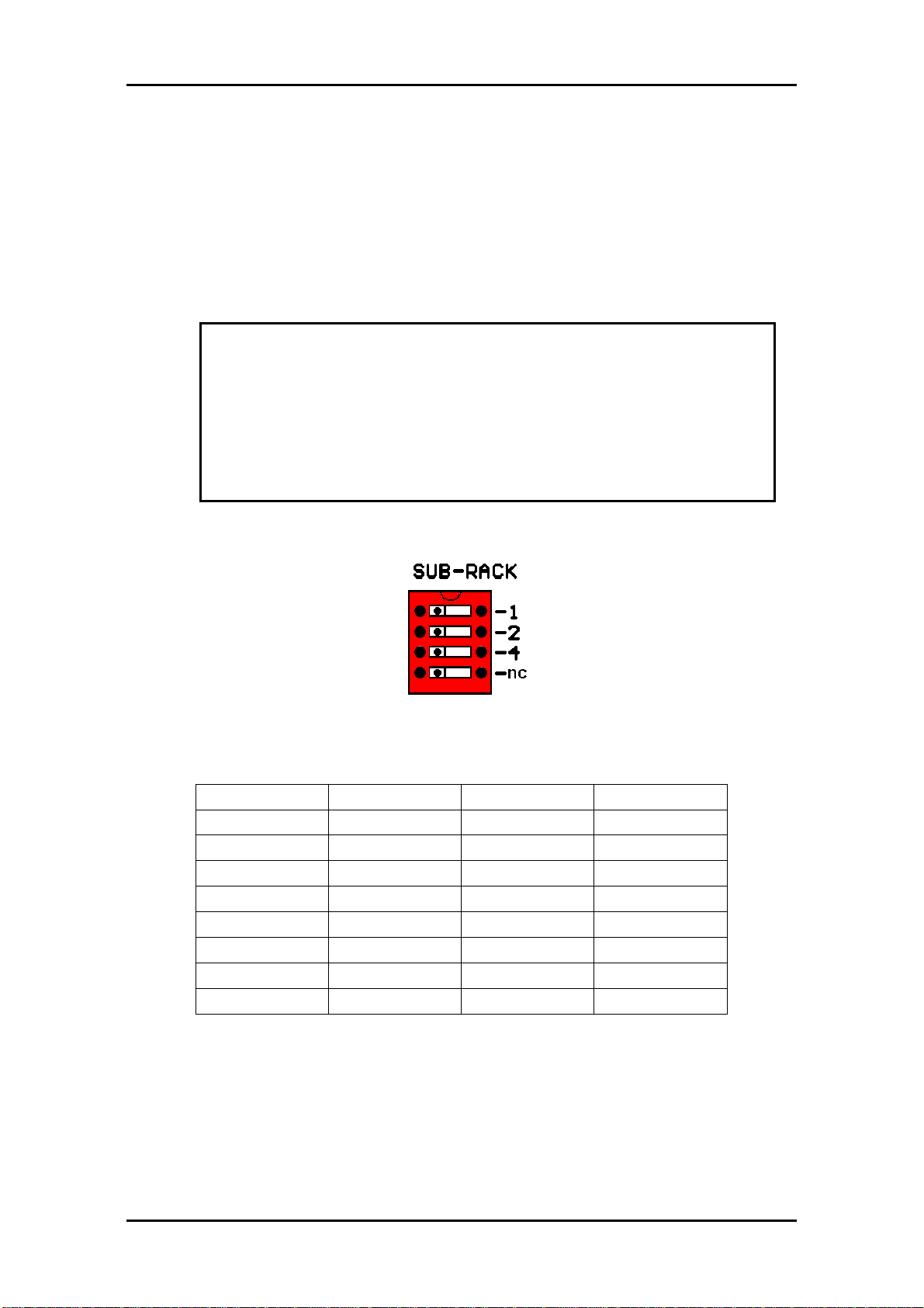
3.1 Address setting on each sub-rack
Each sub-rack can be assigned an address through the DIP-switches on the
rear. Maximum 8 sub-rack addresses are available.
This address setting only applies when the sub-rack is used in combination
with a GYDA-SC Rack System Controller.
If you have more than 8 sub-racks together, you need several GYDA-SC Rack
System Controller cards.
The setting of the address of a sub-rack is as follows:
1 0
0means switch to the right (OFF)
1means switch to the left (ON)
SW 4 SW 2 SW 1 Address
OFF OFF OFF 0
OFF OFF ON 1
OFF ON OFF 2
OFF ON ON 3
ON OFF OFF 4
ON OFF ON 5
ON ON OFF 6
ON ON ON 7
Default address is 0.
The GYDA-SC Rack System Controller automatically detects the position of the
cards within each sub-rack.
More detailed information on the RS-422 configuration can be found in a
separate document and at our web site:
http://www.network-electronics.com/
Note!
In order to ensure proper operation of the system, it is
important that no sub-racks controlled by the same
GYDA-SC Rack System Controller card have the same
address set.
Reset the sub-rack after reconfiguring the sub-rack system,
by turning the power off and on again.

FR-2RU-10-2 Rev. 8
8
4Connections
4.1 Power connection
Figure 3 shows the power connections of the sub-rack as well as the RS-422
connections and the DIP-switches for address setting of the sub-rack.
Figure 3: Connector module for the power supply.
AC: Connect mains to the sub-rack with a mains cord with an IEC 320
connector.
DC: Connect the DB9 male connector from the external DC power supply to
the main unit. Tighten the screws to ensure a proper contact. The DC inputs
have the same function; the left input (DC1) is for the left power module
when seen from the rear and DC2 is for the right power module when seen
from the rear.
4.1.1 Pin-out DC1 and DC2 (DB9)
The maximum current drawn from each pin of the DB9 connector is 2,5A.
Pin #1 GND for DC
Pin #2 +5V Output, Max. current: 6A
Pin #3 Relay GPI Output, Normally Open
Pin #4 +15V Output, Max. current: 1A
Pin #5 Positive part of 48VDC supply Input
Pin #6 -5V Output, Max. current: 1A
Pin #7 Relay GPI Output, Normally Open
Pin #8 -15V Output, Max. current: 1A
Pin #9 Negative part of 48VDC supply Input
Pin 1, 2, 4, 6 and 8 are common to both DC1 and DC2. (I.e. they are
physically connected).
A green LED will light on the front when the power supply is in operation.

FR-2RU-10-2 Rev. 8
9
4.1.2 GPI Power Supply Status outputs
The GPI module status outputs can be used for wiring up alarms for third
party control systems.
In case of power failure, pins 3 and 7 will be physically connected (low
impedance), otherwise the connection between pins 3 and 7 will be high
impedance.
4.2 RS-422 connection
At the rear end of the sub-rack is an RS-422 bus. When used in combination
with the GYDA-SC Rack System Controller, up to 8 sub-racks can be
controlled. On the rear end of the sub-rack are DIP-switches where each sub-
rack can be assigned its own address (see figure 3).
The RS-422 interfaces are shown in figure 3.
4.2.1 Pin-out RS-422 (RJ45)
Pin #1 Rx A (+)
Pin #2 Rx B (-)
Pin #3 Tx A (+)
Pin #4 Reserved
Pin #5 Reserved
Pin #6 Tx B (-)
Pin #7 Not Connected
Pin #8 Not Connected
Figure 4: RS-422 pin-out.
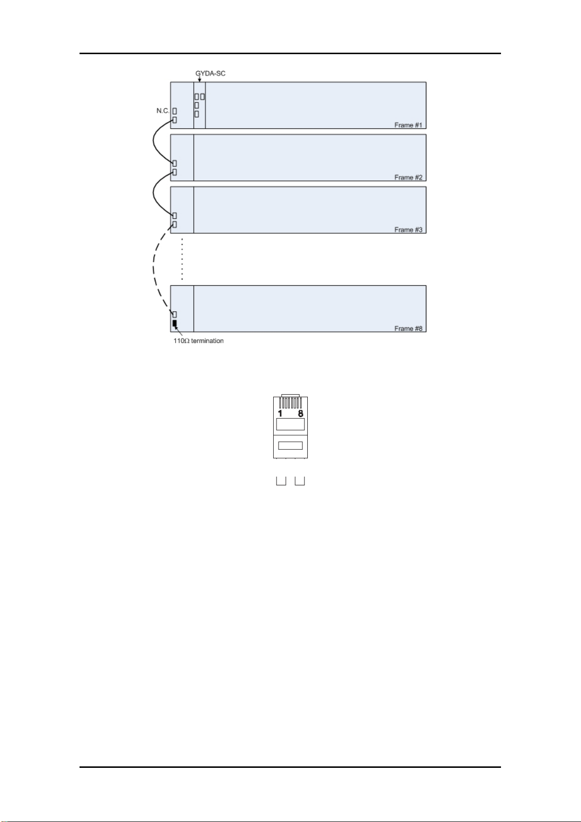
4.2.2 Connecting several sub-racks together
Several sub-racks can be connected to each other through the RS-422 ports
on the rear of each sub-rack.
One GYDA-SC controller can control maximum 8 sub-racks.
You start with the sub-rack containing the GYDA-SC Rack System Controller,
and use 1 RS-422 port to loop through to the next.
The last sub-rack connected must be terminated with 110Ωin order to ensure
proper operation. The other port of the rack containing the GYDA-SC
controller must be left open, and cannot be connected to other sub-racks.
Figure 5 shows an example of how to connect 8 sub-racks together as seen
from the rear end. By using the RS-422 interface at the GYDA-SC controller
card, we control 8 sub-racks via one RS-422 bus.
FR-2RU-10-2 Rev. 8
10
Figure 5: Control of 8 sub-racks with GYDA-SC.
The 110Ωtermination plug used is a standard RJ45 plug with the following
internal wiring:
Figure 6: RS-422 termination.
In the figure above, Pin 1 is connected to Pin 2 with a 110Ωresistor, and Pin 3
is connected to Pin 6 with a 110Ωresistor.
1236

FR-2RU-10-2 Rev. 8
11
5Sub-rack operation
In order to reconfigure or expand the number of modules within a sub-rack,
the front panel must be removed. Each module has a corresponding
connector module at the rear, and is hot swappable.
5.1 Removing the front panel
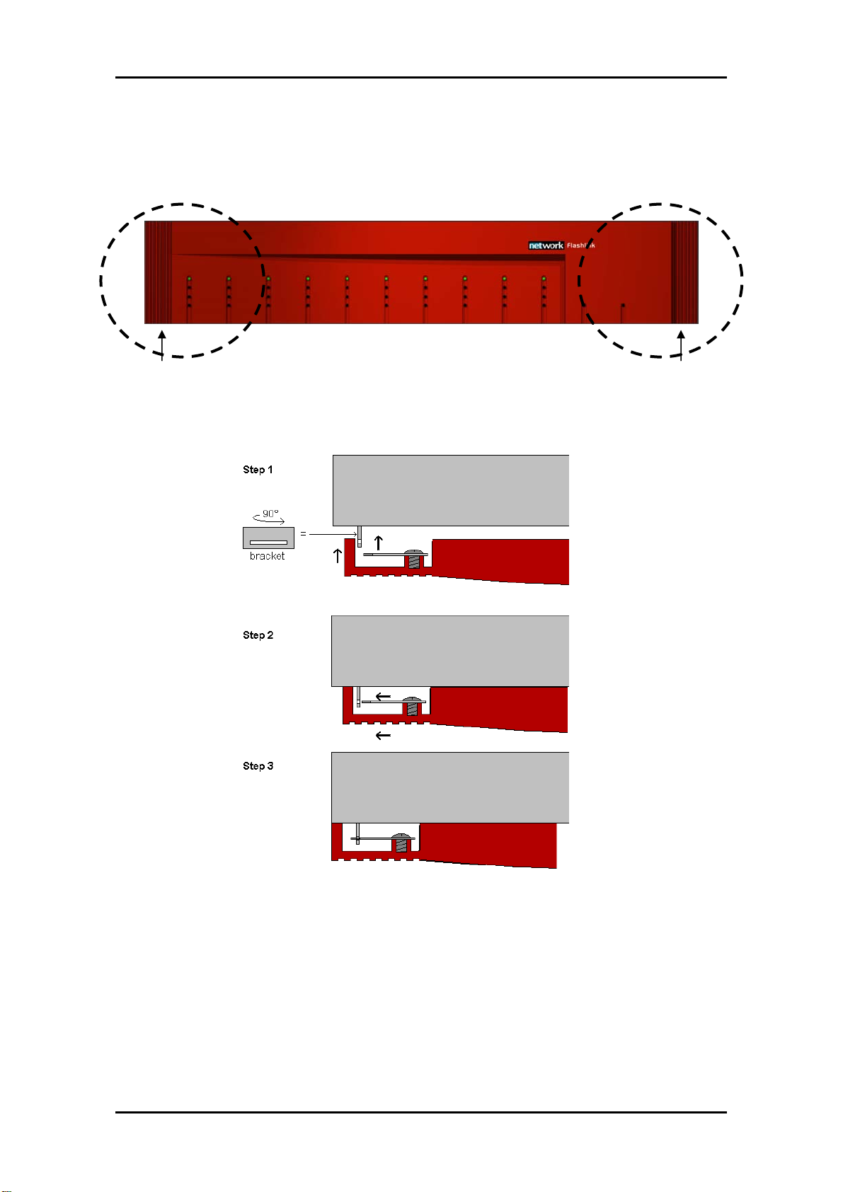
Detach the front panel by putting your fingers on the right hand side of the
front panel and pull gently, as shown in the figures below. Then pull the front
panel slightly to the right before removing it.
Hold here Pull here
"Left circle" "Right circle"
Figure 7: Removing the front panel.
A more detailed description of how the front panel is detached is given in
figure 8.
Step 1 looks at the details in the "right circle" seen from the right hand side,
whereas the next two steps (step 2 and step 3) gives the details of the "left
circle" as seen from the top.
Note!
Use safety goggles when hot-swapping module cards.
If a receiver card is removed from the sub-rack, an invisible laser
beam may be emitted inside the sub-rack from the laser at the
other end. The laser beam might be harmful to your eyes.

FR-2RU-10-2 Rev. 8
12
Figure 8: Removing the front panel (continued).
5.2 Back plane insertion
You must install the accompanying back plane card before you can insert a
new module card into the frame.
Switch off the power with the power switch on the power-supply modules.
The green light on the power module is now switched off. If the power supply
is redundant, make sure that both power supplies are off.
Remove the flashlink module card from the card slot, according to the
procedure in Chapter 5.4. Also remove any card in the position to the right
(seen from the front of the frame). Please follow anti-static procedures when
handling circuit boards with active components.
FR-2RU-10-2 Rev. 8
13
Remove all 4 screws (2 screws if a blind back plane is mounted) from the back
plane to be replaced. Remove the back plane by lifting it straight out from
the rear of the frame.
Remove the screws on the back plane to the left of where the new back plane
is to be installed (seen from the back of the frame). Lift the right hand side of
it slightly.
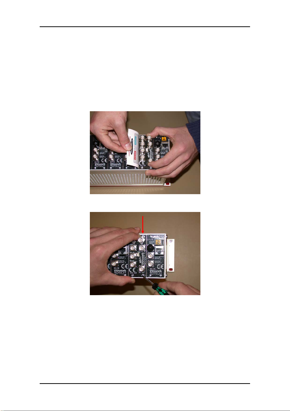
Insert the new back plane. Carefully place the right hand-side of the back
plane into the slot first (this is the side without the EMC shielding.) Then, use
your business card (or another suitable card), and insert the left edge of the
back plane as shown in Figure 9 below. This will help avoid is damage to the
EMC shield when inserting the new back plane.
Figure 9: Inserting a new back plane.
Figure 10: Inserting a new back plane (continued).
Before tightening the screws, use one of your fingers to force the back plane
to the bottom of the frame as shown in Figure 10. Tighten the 2 screws at the
bottom of the back plane first. This is to avoid mismatch between the
connector on the back plane and the PCB. Follow this procedure also for the
back plane to the left.
Downward
Pressure

FR-2RU-10-2 Rev. 8
14
5.3 Card insertion
After the front panel is removed, full access to the card modules inside the
sub-rack is given.
Switch off the power with the power switch on the power-supply modules.
The green light on the power module is now switched off. If the power supply
is redundant, make sure that both power supplies are off.
The sub-racks are equipped with plastic guide rails to align the module cards
into their respective positions 1 to 10. Just before the cards are inserted one
should remove the plastic cap from the fiber ferrule as shown in figure 11. Do
not touch the ferrule tip with your fingers (see chapter 6.2 - fig. 21).
Figure 11: Removal of plastic cap
Figure 12: Overview of card positions inside a sub-rack
Note!
Be careful when inserting the card into the sub-rack.
The ferrule of the fiber may be damaged if it touches the sub-
rack walls. Do not touch the ferrule tip with your fingers.

FR-2RU-10-2 Rev. 8
15
Figure 13: Inserting module cards
Slide the card into the plastic guide rails inside the sub-rack until the red
handle is close to the sub-rack front. A detailed description of the last part of
the insertion process is shown in figure 14.
Figure 14: Inserting module cards (continued)
On the top of the rack is a hole above each module slot. When the tip of the
handle is just below this hole (fig. 14 a)), start to bend the handle downwards
as in figure 14. The tip of the handle enters the hole and the card is locked
and proper contact ensured when the handle is in upright position (figure 14
b)).
Make sure that the connector on the module card fits with the connector on
the back plane card when inserting a new module card for the first time.

FR-2RU-10-2 Rev. 8
16
5.4 Card removal
To remove a module card from the sub-rack frame, release the card by
moving the red handle until it is in horizontal position see figure 15 a). Then
pull the card out of the sub-rack with the red handle (figure 15 b). After
removing a card, it is important that the protective cap is put back on the
ferrule tip (figure 15 c) and d).
Figure 15: Removal of module card.
Note!
When removing a receiver card from the sub-rack (hot
swapping), the laser beam may be present inside the sub-rack
(transmitted through the fiber). To avoid damaging your eyes,
never look directly into the sub-rack unless you are 100,0 %
sure that no laser beam is present inside the sub-rack.
Note!
It should not be necessary to use any force when entering the
module card into the accompanying back plane connector.

FR-2RU-10-2 Rev. 8
17
5.5 Adding new module cards
Figure 16: Overview of rear end of sub-rack showing blanks and connector modules
If a sub-rack is not fully equipped, there will be some unused card slots.
These slots have no connector modules, but a blank at the rear, as shown in
figure 16.
Modules are stacked from position #1 and up to position #10. In figure 16 the
next module shall be in position #3. The only exception is the GYDA-SC
controller, which shall always be in position #10.
Add modules by removing the blanks at the rear and replacing them with the
connector module for the new card. A blank has two screws, and a connector
module has four screws.
The copper finger strips around the edges of the connector modules and the
blanks ensure the EMC-shielding. Care should be taken when removing the
modules/blanks, so the finger strip is not torn off. This also applies when
inserting the modules / blanks.
The connector modules with an optical interface have a rubber plug inside
each connector case to protect from dust. This rubber plug must be removed
before the module cards are inserted.
After the connector modules are mounted, the module cards can be inserted
as described in section 5.3.
Figure 17: Removing the rubber plug from module cards.
FR-2RU-10-2 Rev. 8
18
5.6 Attaching the front panel
To attach the front panel, we invert the process described in section 5.1. Start
by switching on the power supplies.
"Left circle" "Right circle"
Figure 18: Attaching the front panel.
We start in the "left circle" and slide the front into the slot as described in
figure 19.
Figure 19: Attaching the front panel (Top view of left corner).
After the front is attached to the left part of the sub-rack we attach in to the
right part as shown in figure 20.

FR-2RU-10-2 Rev. 8
19
Figure 20: Attaching the front panel (continued)
A click can be heard, and the front is attached.

FR-2RU-10-2 Rev. 8
20
6Fiber optics
The FR-2RU-10-2 may house fiber-optic equipment.
Even though a fiber-optic cable can look almost the same as an electrical wire,
special care must be taken. Inside the cable is a fiber made of glass. Glass has
very different physical properties than the copper used in electrical wires.
6.1 Handling of optical fibres
In practical terms this means that these precautions must be taken:
-Do not bend the fiber too much
-Do not put anything on top of the optical fiber.
-Keep the connectors clean from dust
If a fiber is bent to much, parts of the transmitted light is lost.
We can compare light transmission through an optical fiber with driving a car
at maximum speed. We want the road to be as straight as possible. The
probability that your car is still on the road at the other end of the turn
decreases with increasing curvature of the turn. However, there is a major
difference. The transmitted light is gradually lost when the curvature
increases, while your car is either on the road, or not.
Therefore all the datasheets of optical fibres have a point called "minimum
bend radius" or something similar. This means that any bending of the fiber
corresponding to a bend radius less than the given value, will make the light
leak out of the fiber.
A typical value is 20 mm to 40 mm (Bellcore standard) for single mode fibres.
You should also avoid putting any heavy items on top of the optical fibres,
because this will change the optical properties of the fiber, and contribute to
errors in the transmitted signal.
Unless the fiber is damaged, it will regain its optical properties after a bend is
straightened out or the items are removed / the squeeze is released.
Note!
When patching at the rear of the sub-rack it is extremely
important that you don’t look directly into the fiber end.
If laser light is emitted this can destroy your eye. As a rule of
thumb:
Never look directly into a fiber end. This also applies inside
the sub-rack if a module is removed.
Table of contents
Popular Power Supply manuals by other brands


Emerson
Emerson NetSure-48 VDC Power System installation instructions

GW Instek
GW Instek PFR Series Start guide

Matsusada Precision
Matsusada Precision eK-FG2 instruction manual

Matsusada Precision
Matsusada Precision VOL Series instruction manual

Phoenix Contact
Phoenix Contact EV-T2M3SO12-3P-P-SET manual

Vanderbilt
Vanderbilt SPCP432 instructions


