PSS GP800 Power Series User manual

On-line uninterruptible power supply
User manual


-i-
Contents
CONTENTS............................................................................................................I
1BRIEF INTRODUCTION.............................................................................1
1.1 PROLEGOMENON ......................................................................................1
1.2 FIVE DESIGN POINTS .................................................................................1
1.3 NOTE........................................................................................................1
2CONFIGURATION AND FUNCTION .......................................................3
2.1 FRONT PANEL ...........................................................................................3
2.2 APPEARANCE............................................................................................5
2.3 SWITCH POSITION AND FUNCTION.............................................................6
3PLACEMENT NOTES..................................................................................8
3.1 TRANSIT OR MOVE....................................................................................8
3.2 PLACEMENT .............................................................................................8
4INSTALLATION .........................................................................................11
4.1 INPUT .....................................................................................................11
4.2 OUTPUT..................................................................................................14
4.3 DC INPUT WIRING...................................................................................17
5OPERATION PROCESS ............................................................................18
5.1 PREPARATION BEFORE START-UP.............................................................18
5.2 OPERATION PROCESS FOR FIRST START-UP ..............................................18
5.3 OPERATION PROCESS FOR ROUTINE TURN-OFF........................................20
5.4 OPERATION PROCESSIF UPS IS NOT IN USE.......................................20
6STATUS HANDLING..................................................................................21
6.1 SYMBOL SIGNIFICATION ..........................................................................21
6.2 STATUS INDICATIONAND HANDLING..........................................21

-ii-
7UPS CONFIGURATION IN DIFFERENT MODES................................30
7.1 UPS IN NORMAL MODE...........................................................................30
7.2 UPS MODE WHILE UTITILTY POWER FAIL.....................................30
7.3 UPS IN STATIC BYPASS MODE ...............................................................31
7.4 BATTERYAND CHARGER.........................................................................31
7.5 DAILY MAINTENANCE.............................................................................32
8COMMUNICATION INTERFACE...........................................................33
9SPECIFICATION........................................................................................36
10 SHIPPING LIST ..........................................................................................38

-1-
1BRIEF INTRODUCTION
1.1 Prolegomenon
The product is designed for mini to micro level computer companies
who is looking for exquisite quality, excellent function and easy to operate.
This product is the optimum power supply partner for the office and ensures
you can attain optimal clean power quality.
1.2 Five design points
1. Slim design
2. Light weight and convenient to transport
3. Reliable and easy to operate
4. Convenient to maintain
5. Packaged material with environmental protection
1.3 Note
The manual explains how to operate and maintain the system.
To optimize the use of the UPS, please note the following:
1. Read the manual carefully before use
2. Perform the operation strictly according to operating process
3. Place the UPS in a convenient, dry and safe area.
4. Install the power according to the instructions manual
5. Do not open the covers to avoid injury
6. Please charge batteries once every 6 months if not in use
7. Do not overload the UPS
8. Keep the manual for the future reference
9. Do not use the UPS while in fault condition. See manual for various
troubleshooting methods
10. Please keep UPS area clean and run in a temperature controlled

-2-
environment.
11. Do not leave objects on top of the UPS
12. Do not obstruct the air flow
-3-
2CONFIGURATION AND FUNCTION
2.1 Front panel
1) Welcome screen
WELCOME
×××××××××
2) Display of system status
×××××
××KVA.
3) Display of input voltage value*
ON LINE
AC IN:230V
4) Display of input frequency value*
ON LINE
AC FRE:50Hz
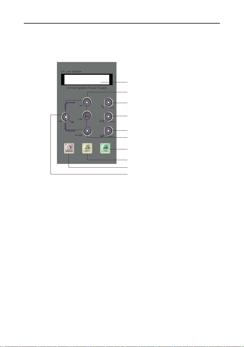
Figure 1 Symbol instruction of front panel indicator.
LCD
Output indicator
Fault indicator
Battery energy indicator
Overload indicator
Bypass indicator
Switch ON
Switch OFF
Cycle display botton
Input indicator

-4-
5) Display of output voltage value*
ON LINE
OUTPUT:230V
6) Display of output frequency value
ON LINE
OUT FRE:50Hz
7) Display of output power percentage
ON LINE
LOAD:80%
8) Display of battery voltage value
ON LINE
BATTERY:218V
9) Temperature display in machine
ON LINE
TEMP:33℃
Note:ON BYPASS mode,the output voltage and frequency
are displayed “0”. LED would display only after the unit is
switched on.
*These parameters vary with machine model.
10) LCD cycle display switch button: digital signal display items
switch button.
11) UPS switch button: UPS general switch button.
(1) Turn on UPS inverter by pressing the “ON” key. UPS
convert to UPS inverter power output 20s later, UPS pure
sine wave AC output power is supplied by UPS internal
power supply equipment.
(2) By pressing the OFF switch button for 3s,the inverter
shuts down and the UPS turns to bypass mode.
The button acts as general switch.
-5-
2.2 Appearance
1
2
7
3
4
5
6
8
9
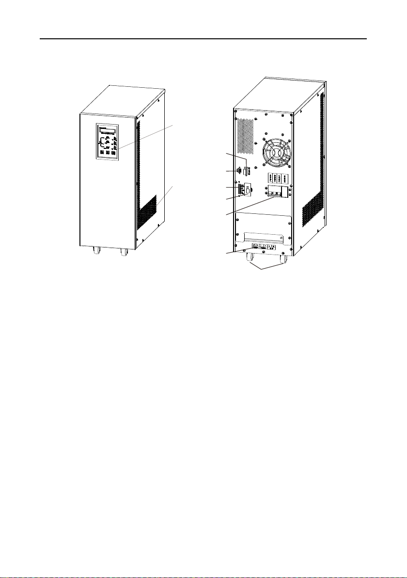
1. Control panel: UPS display and operation panel
2. Emission heat ventilation hole: The ventilation hole and other small
long ventilation holes should be kept open for good ventilation.
3. RS232 communication interface: Standard communication interface
between UPS and computer.
4. Power switch: Power switch controls input, output and battery
power switch at the same time.
5. Wiring terminal: Power wiring terminal for input, output and battery
connections.
6. Dry contact (optional): 4 routes 10A dry contact output
7. Wheels: Movable wheels
8. SNMP card (optional): remotely monitor the UPS
9. RS485 (Optional): communicate with UPS
Figure 2 Front panel
Figure 2 Front panel
Figure 3 Rear panel
-6-
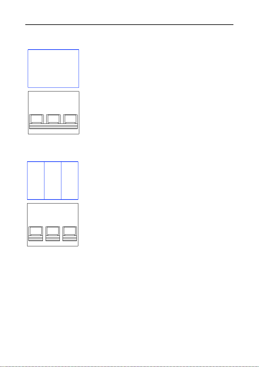
2.3 Switch position and function
1. Input switch: when turned on, the UPS is
connected with AC and battery power
Switch position: (1-3kva 48v)
1. BYPASS OUTPUT SWITCH
When switch is turned on, power is provided to the
UPS and the UPS runs in bypass.
2. RECTIFIER INPUT SWITCH
When switched on, theAC will be rectified.
3. BATTERY INPUT SWITCH
When turned on, the battery begins to charge and
discharges accordingly.
Switch position: (1-3kva 192v)
4. OUTPUT SWITCH (optional): when turned on,there is output power
5. MAINTENANCE BYPASS SWITCH (optional): When turning on the
switch, the AC will bypass the UPS and supply power to the load without the
UPS. The UPS can be serviced or repaired
INPUT
RECTIFIER
BYPASS
BATTERY

-7-
Switch Position (15-20kva)
1. BYPASS OUTPUT SWITCH When switch is turned on, power is
provided to the UPS and the UPS runs in bypass.
2. AC INPUT SWITCH When switched on, theAC will be rectified.
3. BATTERY INPUT SWITCH When turned on, the battery begins to charge
and discharges accordingly.
4. OUTPUT SWITCH (optional): when turned on, there is output power.
5. MAINTENANCE BYPASS SWITCH (optional): When turning on the
switch, the AC will bypass the UPS and supply power to the load without the
UPS. The UPS can be serviced or repaired
-8-
3PLACEMENT NOTES
3.1 Transit or move
1. Please disconnect all connections. (First turn off before performing)
2. Please do not move UPS while functioning.
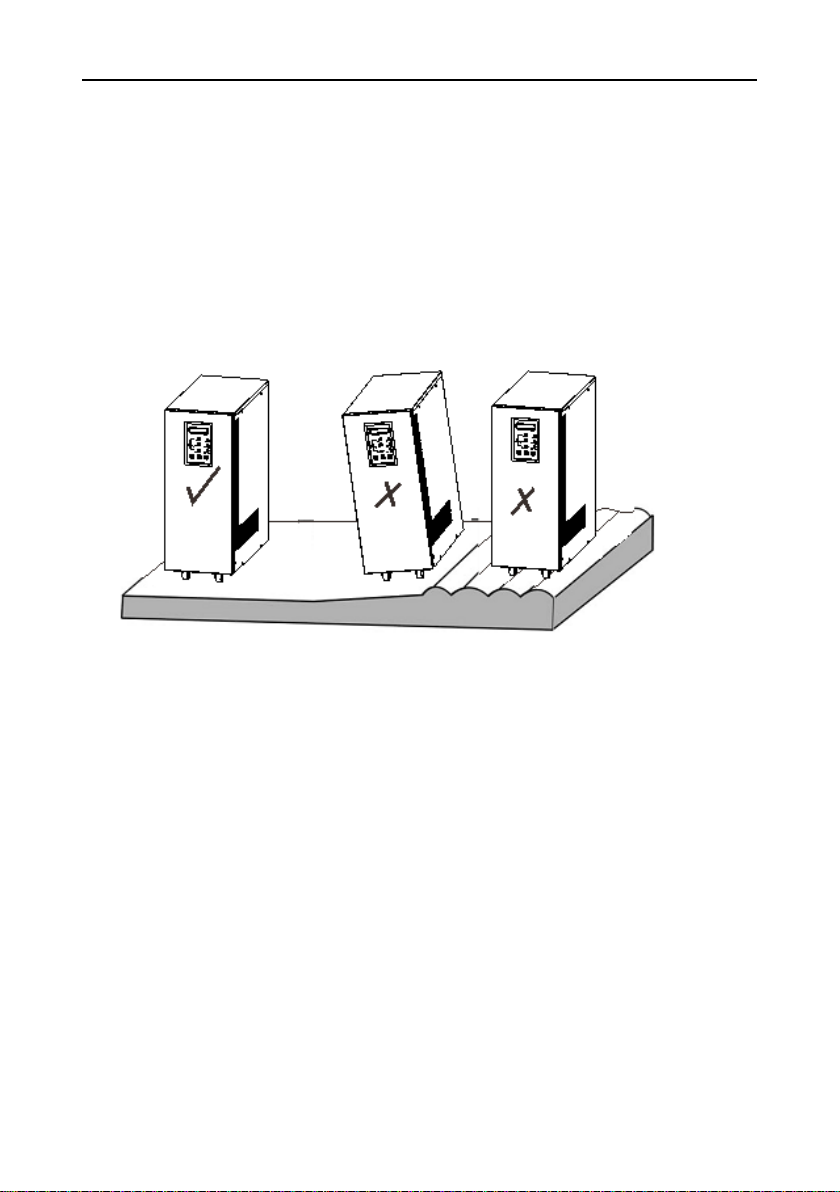
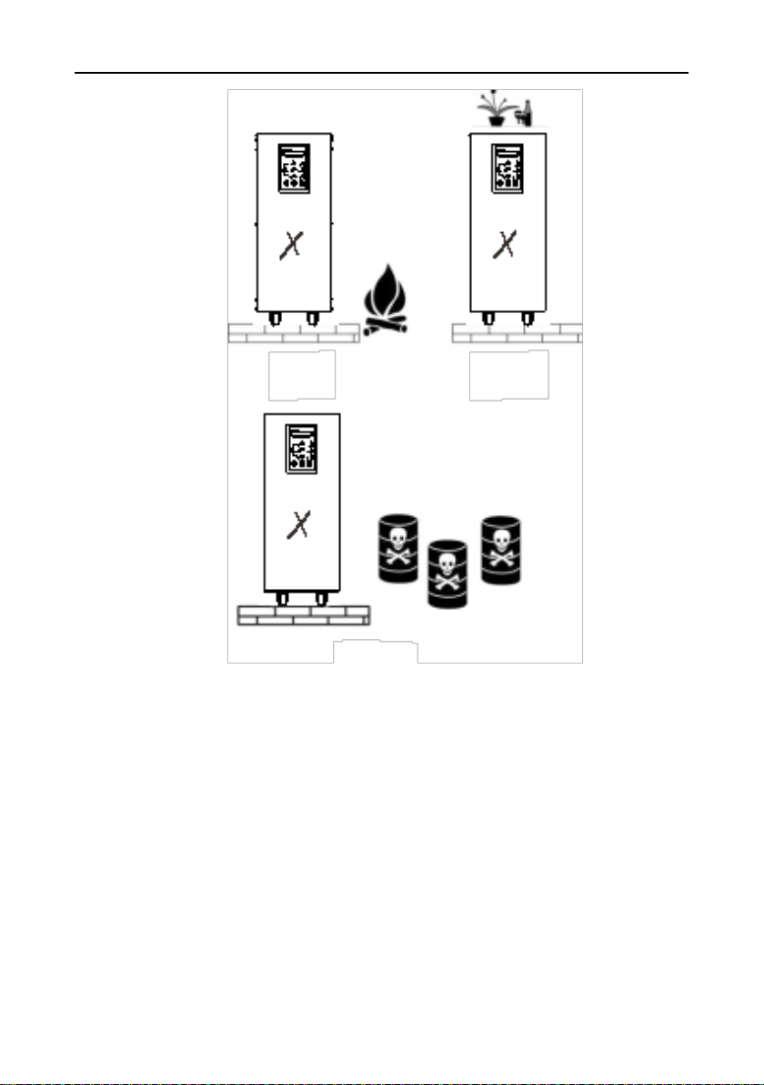
3.2 Placement
1. Do not place the UPS on a slope or uneven surface. (Figure 4)
Figure 4
2. Place the UPS in a room where there is good ventilation. The rear
panel of UPS and two side faces should be more than 10cm away
from the wall. (Figure 5)
3. Do not install the UPS in direct sunlight, rain or damp areas. (Figure
6, 7)

-9-
Figure 5
Figure6 Figure 7
4. Please keep away from any fire source and high temperatures to
avoid overheating. (Figure 8)
5. Do not place goods on the UPS. (Figure 9)
6. Do not install the UPS in places which contains caustic gasses.
(Figure 10)
7. Running environment temperature: 0℃-40℃.
-10-
Figure 8
Figure 10
Figure 9
-11-
4INSTALLATION
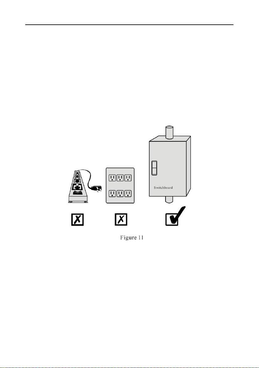
4.1 Input
1. Forbid using general household sockets, the maximum current of
general sockets is 15A, the socket may cause fire because of overload.
2. Turn off power when connecting cables, prohibit operation on live
wires.
3. Please connect UPS input terminal to utility power from a switchboard.
Figure 11.
Note: Do not swop live and neutral
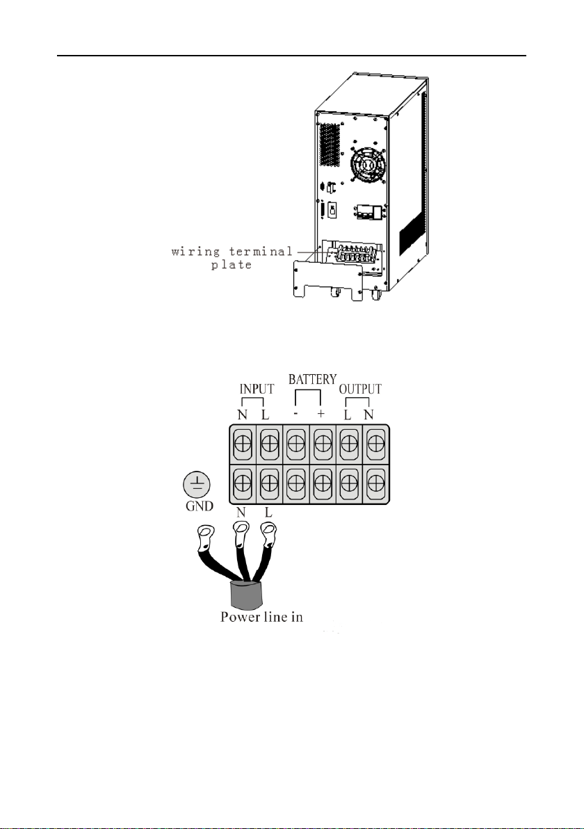
4. Back panel position and connection
(1) Remove two screws with “+” screwdriver (Figure 12)
(2) Open the back panel and inspect the wiring terminal below the
power switch. (Figure 13)
5. Feed in the input, output and battery pack power cables through the
inlet/outlet hole and connect to the terminal block on the UPS.
-12-
Figure 12
Figure 13
6. Connect power correctly
(1) Live (L): There is 220V relative to other two holes.
(2) Neutral (N): there is 220V relative to the Live, there is 0.5-2V
relative to the ground. (Load current circulate through neutral)

-13-
(3) Ground (G): Connect correctly to ground in the switchboard.
7. If the difference between the neutral and the ground is more than 2V
or it cannot meet the requirements, please reinstall good grounding to
ensure safety of UPS operation.
8. The comparison list of input current rating and input cable size is as
follows:
Model
Max. input
Input wire
Terminal specification
1KVA
8.5A
12AWG
5.5-5
2KVA
14A
10AWG
5.5-5
3KVA
17.5A
10AWG
5.5-5
4KVA
22.5A
10AWG
5.5-5
6KVA
31A
10AWG
5.5-5
8KVA
40A
8AWG
8.5-6
10KVA
50A
8AWG
8.5-6
12KVA
60A
6AWG
16-6
15KVA
72A
6AWG
16-6
20KVA
90A
4AWG
25-6
Table 1
9. The power cable and terminal must be a first-grade product
manufactured by an authentic manufacturer.
10. Do not wrap the power cables around the terminal block screws.
11. After fastening the input cable, to avoid short-circuit, please see if the
input cable contacts properly and does not touch other wiring.
12. Follow the electrical laws when doing installation.
13. Avoid using the same circuit breaker with other equipment when
connecting to the switchboard.

-14-
14. For 3Ø 4-wire connections,
please respectively measure
the voltage between R/N,S/N,
T/N with a meter and see if
they are close to 220V, then
connect L cable of the UPS to
the cable whose voltage
measured the highest
(meaning supply power of this
phase is lighter than that of the
other two phase), the N cable
of UPS is connected to utility
neutral cable N, the UPS-GND
is connected to the grounding
club.
15. If the model of the unit you purchased is 110V input, please connect
UPS-L cable into line, connect N cable into neutral cable, and connect
UPS-GND cable to grounding club.
Please note that this equipment is single phase 220V or 110V, do
not connect to 3 phase 380V.
4.2 Output
1. Please refer to output installation table 2 when installing.
2. Position and way of connection, refer to figure 15.

-15-
3. Output power cable should be sized according to UPS size, do not use
undersized cabling. Please refer to Table 2
Model
Max. output current
Output cable
Terminal specification
1KVA
4A
12AWG
5.5-5
2KVA
7.5A
10AWG
5.5-5
3KVA
11A
10AWG
5.5-5
4KVA
15A
10AWG
5.5-5
6KVA
22A
10AWG
5.5-5
8KVA
30A
8AWG
8.5-6
10KVA
36A
8AWG
8.5-6
12KVA
44A
8AWG
16-6
15KVA
55A
6AWG
16-6
20KVA
72A
6AWG
16-6
Table 2
4. Avoid short-circuit and overload.
5. The comparison between output current rating and output cable size is
listed in Table 2.
6. The ground to this unit only acts as reference point, if the grounding is
bad, that may cause disturbance and false management, and affect UPS
performance. Speak to professional personnel for assistance

-16-
immediately.
7. Use a good grounding system.
8. Try to make the ground close to the connecting point of the grounding
club or origination point in the switchboard. Please refer to figure 16.
* Please install wiring according to input voltage
Contact an electrician or our service department if there is problem with
the installation.
Table of contents
Popular Power Supply manuals by other brands

ELTEX
ELTEX ES53 Series operating instructions

Optimal Power
Optimal Power OPR150-48S manual

Antec
Antec SMARTPOWER 2.0 Manual Del Usuario

Intel
Intel ATX 0.9 Design guide

Enterasys
Enterasys SecureStack C2 C2RPS-POE installation guide

Lindsay Broadband
Lindsay Broadband LBVM900 Series Installation and operation manual

Rigol
Rigol DP800 Series Firmware Upgrade Instructions

Thermal Dynamics
Thermal Dynamics CE CutMaster 50 operating manual

Agilent Technologies
Agilent Technologies Series N6700 user guide

Spellman
Spellman SL2KW SERIES instruction manual

Bosch
Bosch AL 1830 CV Original instructions

Agilent Technologies
Agilent Technologies 6010A Specifications


