NEURON THC User manual

NEURON
C N C E L E C T R O N I C S
INDUSTRIAL
TORCH HEIGHT
CONTROL
NEURON CNC ELECTRONICS
08.01.2020
USER MANUAL

USER MANUAL
System Description
When operating a CNC Plasma table, it is important to maintain a fixed cutting height of the
torch throughout the cutting process in order to achieve good cut quality. While the plasma torch
tip-to-plate distance can be automatically set at the start of a cut by the Initial Height Sensing
(IHS) switch, it is difficult to maintain this exact height throughout the cut. Remember that a
typical plasma cutting torch tip-to-plate distance is only 1.5 mm and that normal sheet metal and
plate stock are not perfectly flat. In addition, the heat generated during the cutting process can
cause warpage in the material which makes it even more difficult to maintain this stand-off
height. If the torch gets too close to the material during cutting it can cause premature wear to
the cutting nozzle and also result in more backside dross. Even worse, the torch can crash into
the material if the plate is warped enough over a longer cut which consumes some of the 1.5 mm
starting cut height. Conversely, if the torch pulls too far away from the material it can negatively
impact the cut quality and also cause the torch to lose the arc during cutting.
The THC module functions based on the principle that the amount of voltage in the plasma arc
between the torch and the material is directly proportional to the length of the plasma arc. In other
words, if the torch is closer to the plate the arc voltage will be less than if the torch is further away
from the plate assuming all other cutting parameters are equal.
The Neuron.THC torch height control system is the most technologically advanced arc
voltage control system in the plasma cutting industry. It is designed to offer arc voltage control
capabilities to any plasma cutting system. The Neuron.THC quickly and accurately sets the arc
transfer height of the torch using an “Ohmic” or/and “Float Head” plate sensing technique. The
Neuron.THC system uses advanced DSP (digital signal processing) software servo control loops to
control speed, position and arc voltage with unparalleled precision. The system is fully
programmable via 10/100 Base-T Ethernet communications.
The Neuron.THC can attain speeds in excess of 200 inches per minute in the arc voltage control
mode and speeds in excess of 500 inches per minute in the position control mode.
Safety
Installation, as well as repairs, made to the Neuron.THC System should only be performed by
qualified personnel. The Neuron.THC system use D.C. for operation. In addition, it will be necessary
to make connections to the D.C. output of the plasma power supply. These voltages can be in
excess of 300 volts. Fatal shock hazard does exist. Exercise extreme caution while working in these
areas. Please refer to the plasma power supply manufacturer’s operating manual for additional
information.
Various other safety hazards exist while operating a plasma arc cutting system. Please see the
plasma power supply manufacturer’s operating manual for information on eye, skin, and hearing
protection, as well as other information required to safely operate the equipment.
System Components
The Neuron.THC System consists of the following components:
•Control module
•Plasma interface module
•Operator’s control module
•UCCNC Plugin and Screen set for plasma cutting applications
Control module
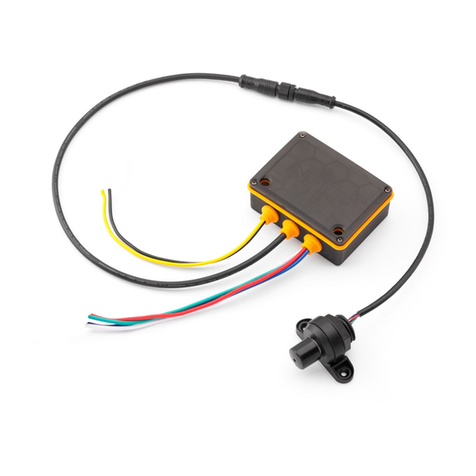
The control module houses a microcontroller, and I/O interface. This unit provides arc voltage
control, and interfaces with the torch driver through the Pulse/Direction interface, the CNC UCCNC
machine through the Ethernet interface, and the plasma system through standard discrete I/O
interfaces.

USER MANUAL
Plasma system interface module
It provides precise, scaled feedback of the plasma arc voltage to the control module. It also
provides a convenient control signal interface to the Neuron.THC.
Operator Control Module
The Operator Control Module includes screw terminals for connection “Cutting Run/Stop” switch,
“Torch Up”, “Torch Down” buttons and an installed rotary/push knob selector for THC setup and
control.
Specifications
Input power
12V DC, 0.8A
Operating temperature
-10º C to 40º C
Operating humidity
95% relative humidity
Pulse/Dir interace
Open collector, protected +5V 100mA
Ethernet communication
Shielded RJ-45 Cat-5e, Up to 100 m (4-wire Cat-
5e), I/O transmission speed 10/100 Mbps auto-
negotiation
Parallel digital input
NO/NC dry contact
Lifter limit switches
Home switch, IHS switch and Ohmic sensor
Maximum Z axis speed
15000 mm/min
Voltage divider ratio
10:1(internal), 20:1 (Hypertherm cutter)
Arc voltage range
25-250V
Warranty
1 year
Control module has a size 145x90x45 mm with DIN mounting standard and can be easily
embedded inside the CNC box.

USER MANUAL
Plasma interface board (Divider)
Operator panel board

USER MANUAL
Features
The Neuron.THC comes standard with the following features:
•Works with ALL plasma cutters
•Connect via 10/100 Base-T Ethernet interface to UCCNC CNC and controls Z axis directly
(Internal motion controller, Software DSP (digital signal processing) control loop, 500 uSec
cycle)
•Unlimited number of cut profiles for different metal thicknesses. Quickly switch between
profiles and the ability to quick edit them
•Set point resolution - 0.25V
•Set point range - 25 - 250V (set just by clicking the mouse button and wheel on the
Target Arc Voltage textbox on Control Panel or turning the encoder knob on the operator
panel)
•Maximum control accuracy - +/- 0.25V
•Height control accuracy +/-0.125 mm (.005") using a properly configured Z-axis.
•Voltage feedback (divider) - 1:20 (for Hypertherm), 1:10 (internal) of Arc Voltage
•100 kHz maximum step frequency (50% Duty cycle)
•Automatic or manual control of the cutting sequence
•Sample voltage mode - THC measures the voltage at the end of the AVC Delay and uses it
as a set point for the remainder of the cut.
•Programmable THC OFF (Hold signal) control to help prevent torch crashing when end of
cut, circle of small radius - enable/disable, mm.
•Programmable arc voltage limiter to help prevent torch crashing when crossing a kerf -
enable/disable, level, voltage
•Programmable arc voltage control loop proportional gain (system response)
•Skip IHS mode - If the next starting point is within this distance of the end of the previous
cut, the THC skips the IHS.
•Improved Jog - the lifter initially jogs 0.25 mm. After 0.5 second, it begins continuous
motion at the IHS Speed. After 1.5 seconds, the lifter increases the speed to the
programmed Manual Speed
Jog just by clicking the mouse button and wheel on the Position textbox or by pressing the
up / down button on Operator Panel
•Automatic Collision Avoidance. This safety feature allows the control to automatically
adjust the torch height during a cut to help prevent torch crashes.
•Retract height selectable between full or programmed partial raise height
•Programmable automatic positioner speed
•Programmable manual positioner speed
•Programmable maximum Z axis stroke (Soft Limit function)
•Programmable arc transfer height
•Programmable pierce height
•Programmable pierce time
•Programmable cutting height
•Programmable AVC (automatic voltage control) delay time
•Programmable torch retract height
•Programmable Jump height above the workpiece that the torch is raised to clear the top
dross puddle that can form during the pierce.
•Programmable IHS (initial height sensing) touch speed
•Programmable crossover height (high-to-low speed transition point)
•Buffered Step & Direction for direct interface to Motor Drive
•All inputs (include arc voltage) are isolated and Simple wiring (RJ45 connectors)
•Built-in pierce and cut time counter to control consumables
•Integrated diagnostic system informs the operator of the errors that occurred
•Ability to tune arc voltage converter
•Plotting the arc voltage and save to file for diagnostics
•Easy Software update using the utility Neuron Flasher

USER MANUAL
System Requirements
Power Requirements
The Neuron.THC system has a terminal block power plug. 12V DC 0.8A required.
Do not use 12V power from CNC PC! Use separated power supply.
The performance of the Neuron.THC is tightly coupled to the lifter and motor characteristics. The
Neuron.THC was designed as a conventional plasma height control and the lifter does not include
any position feedback.
The lifter screw pitch affects the lifter linear speed and the control loop gain when operating with
arc voltage. The lifter friction and maximum torch weight affect the point at which the lifter will
require a brake to maintain position. For these reasons, the motor and lifter characteristics are
critical and must be tightly controlled.
The following is a partial list of lifter and motor characteristics that are compatible with this
controller.
• Lifter Ball screw/Rack pitch = 4 –20 mm/rev
• Lifter with UP limit (homing sensor)
• Lifter capable of 200 in/min.
• Lifter should have low backlash and little mechanical play
WARNING:
The performance of the Neuron.THC is tightly coupled to the lifter and motor
characteristics. To ensure proper operation, a customer designed lifter should be fully
tested with this controller under all anticipated operating conditions.
What Is Plasma
Plasma is a fourth state of matter, an ionized gas which has been heated to an extremely high
temperature and ionized so that it becomes electrically conductive. The plasma arc cutting and
gouging processes use this plasma to transfer an electrical arc to the workpiece. The metal to be
cut or removed is melted by the heat of the arc and then blown away. While the goal of plasma
arc cutting is the separation of the material, plasma arc gouging is used to remove metals to a
controlled depth and width.
Plasma torches are similar in design to the automotive spark plug. They consist of negative
and positive sections separated by a center insulator. Inside the torch, the pilot arc starts in the
gap between the negatively charged electrode and the positively charged tip. Once the pilot arc
has ionized the plasma gas, the superheated column of gas flows through the small orifice in the
torch tip, which is focused on the metal to be cut.
In a Plasma Cutting Torch a cool gas enters Zone B, where a pilot arc between the electrode
and the torch tip heats and ionizes the gas. The main cutting arc then transfers to the workpiece
through the column of plasma gas in Zone C. By forcing the plasma gas and electric arc through a
small orifice, the torch delivers a high concentration of heat to a small area. The stiff, constricted
plasma arc is shown in Zone C. Direct current (DC) straight polarity is used for plasma cutting, as
shown in the illustration. Zone A channels a secondary gas that cools the torch. This gas also
assists the high velocity plasma gas in blowing the molten metal out of the cut allowing for a fast,
slag - free cut.

USER MANUAL
Arc Initialization
There are two main methods for arc initialization.
High Frequency Start
This start type is widely employed, and has been around the longest. Although it is older
technology, it works well, and starts quickly. But, because of the high frequency high voltage
power that is required generated to ionize the air, it has some drawbacks. It often interferes
with surrounding electronic circuitry, and can even damage components. Also, a special circuit
is needed to create a Pilot arc. Inexpensive models will not have a pilot arc, and require
touching the consumable to the work to start. Employing a HF circuit also can increase
maintenance issues, as there are usually adjustable points that must be cleaned and
readjusted from time to time.
Blowback Start
This start type uses air pressure supplied to the cutter to force a small piston or cartridge
inside the torch head back to create a small start between the inside surface of the
consumable, ionizing the air, and creating a small plasma flame. This also creates a “pilot arc”
that provides a plasma flame that stays on, whether in contact with the metal or not. This is a
very good start type that is now used by several manufacturers. Its advantage is that it
requires somewhat less circuitry, is a fairly reliable and generates far less electrical noise
For entry level air plasma CNC systems, the blowback style is much preferred to minimize
electrical interference with electronics and standard PCs but the High frequency start still rules
supreme in larger machines from 200 amps and up. These require industrial level PC’s and
electronics and even commercial manufacturers have had issues with faults because they have
failed to account for electrical noise in their designs.
CNC Plasma
Plasma operations on CNC machines is quite unique in comparison to milling or turning and is
a bit of an orphan process. Uneven heating of the material from the plasma arc will cause the
sheet to bend and buckle. Most sheets of metal do not come out of the mill or press in a very
even or flat state. Thick sheets (30mm plus) can be out of plane as much as 50mm to 100mm.
Most other CNC gcode operations will start from a known reference or a piece of stock that has a
known size and shape and the gcode is written to rough the excess off and then finally cut the
finished part. With plasma the unknown state of the sheet makes it impossible to generate gcode
that will cater for these variances in the material.
A plasma Arc is oval in shape and the cutting height needs to be controlled to minimize
beveled edges. If the torch is too high or too low then the edges can become excessively beveled.
It is also critical that the torch is held perpendicular to the surface.

USER MANUAL
Torch to work distance can impact granularity
Negative cut angle: torch too low, increase torch to work distance.
Positive cut angle: torch too high, decrease torch to work distance.
Note: A slight variation in cut angles may be normal, as long as it is within tolerance.
The ability to precisely control the cutting height in such a hostile and ever-changing environment
is a very difficult challenge. Fortunately, there is a very linear relationship between Torch height
(Arc length) and arc voltage as this graph shows.
This graph was prepared from a sample of about 16,000 readings at varying cut height and the
regression analysis shows 7.53 volts per mm with 99.4% confidence. In this particular instance
this sample was taken from an Everlast 50 amp machine.
Torch voltage then becomes an ideal process control variable to use to adjust the cut height.
Let’s just assume for simplicity that voltage changes by 10 volts per mm. This can be restated to
be 1 volt per 0.1mm (0.04”). Major plasma machine manufacturers (e.g. Hypertherm, Thermal
Dynamics and ESAB), produce cut charts that specify the recommended cut height and estimated
arc voltage at this height as well as some additional data. So, if the arc voltage is 1 volt higher
than the manufacturers specification, the controller simply needs to lower the torch by 0.1 mm
(0.04”) to move back to the desired cut height. Neuron torch height control unit is used to
manage this process.
Arc OK Signal
Plasma machines that have a CNC interface contain a set of dry contacts (e.g. a relay) that
close when a valid arc is established and each side of these contacts are bought out onto pins on
the CNC interface. A plasma table builder should connect one side of these pins to field power and
the other to an input pin. This then allows the Neuron controller to know when a valid arc is
established and also when an arc is lost unexpectedly.

USER MANUAL
Initial Height Sensing
Because the cutting height is such a critical system parameter and the material surface is
inherently uneven, a Z axis mechanism needs a method to sense the material surface. There are
two methods this can be achieved. A “float” switch and an electrical or “ohmic” sensing circuit
that is closed when the torch shield contacts the material.
Float Switches
The torch is mounted on a sliding stage that can move up when the torch tip contacts the
material surface and trigger a switch or sensor. Also, Neuron controller use the switch hysteresis
obtained in the setup procedure.
Regardless what probing method is implemented, it is strongly recommended that float switch
is implemented so that there is a fallback or secondary signal to avoid damage to the torch from
a crash.
Ohmic Sensing
Ohmic sensing relies on contact between the torch and the material acting as a switch to
activate an electrical signal that is sensed by the Neuron controller. Provided the material is
clean, this can be a much more accurate method of sensing the material as a float switch which
can cause deflection of the material surface. This ohmic sensing circuit is operating in an
extremely hostile environment so a Neuron Ohmic contact sensor is implement to ensure safety
of both the CNC electronics and the operator. In plasma cutting, the earth clamp attached to the
material is positive and the torch is negative. It is recommended that The ohmic circuit uses a
totally separate isolated power supply that activates an opto-isolated relay to enable the probing
signal to be transmitted to the Neuron controller.
Corner Lock / Velocity Anti-Dive
The CNC trajectory planner is responsible for translating velocity and acceleration commands into
motion that obeys the laws of physics. For example, motion will slow when negotiating a corner.
Whilst this is not a problem with milling machines or routers, this poses a particular problem for
plasma cutting as the arc voltage increases as motion slows. This will cause the THC to drive the
torch down. Modern CNC systems like Mach3, Mach4, UCCNC, LinuxCNC support the real-time
macros that allow to enable or disable automatic voltage control from program g-code. Neuron
controllers has a separated Hi-Speed “THCOFF” input for this.
Head Safety Lock /Kerf Detect
If the plasma torch passes over a void while cutting, arc voltage rapidly rises and the THC
responds by violent downward motion which can smash the torch into the material possibly
damaging it. This is a situation that is difficult to detect and handle. To a certain extent it can be
mitigated by good nesting techniques but can still occur on thicker material when a slug falls
away. This is the one problem that has yet to be solved within the Neuron controller.
One suggested technique is to monitor the rate of change in torch volts over time (dv/dt)
because this parameter is orders of magnitude higher when crossing a void than what occurs due
to normal warpage of the material. The following graph shows a low-resolution plot of dv/dt (in
blue) while crossing a void. The red curve is a moving average of torch volts.
So, it should be possible to compare the moving average with the dv/dt and halt THC operation
once the dv/dt exceeds the normal range expected due to warpage.

USER MANUAL
Hole and Small Shape Cutting
It is recommended that you slow down cutting when cutting holes and small shapes.
The generally accepted method to get good holes from 37mm dia. and down to material
thickness with minimal taper using an air plasma is:
1. Use recommended cutting current for consumables.
2. Use fixed (no THC) recommended cutting height for consumables.
3. Cut at 60% to 70% of recommended feed rate for consumables and material.
4. Start lead in at or near center of hole.
5. Use perpendicular lead in.
6. No lead out, either a slight over burn or early torch off depending on what works best
for you.
You will need to experiment to get exact hole size because the kerf with this method will be
wider than your usual straight cut.
This slow down and real-time macro for THCOFF can be achieved by manipulating the feed rate
directly in your post processor or by using special rules (for Sheetcam or Plasmicon CAM
software).

Connection diagram

Input signal interface schematic

USER MANUAL
INSTALLATION
1. Mount the Neuron.THC into the CNC box.
2. Connect Home and Initial Height Sensing (Float Head and/or Ohmic Sensor) switches to
screw terminals on the Control Module.
3. Connect the Neuron.THC Control Module to the RJ45 (Cat5e) Ethernet connector on the PC
or Ethernet switch (0.5 m minimal cable length).
4. Connect the plasma system interface PCB to the RJ45 (CAT5) connector on the Control
Module.
5. Connect the Torch Lifter motor driver to Pulse/Direction RJ45 connector (using adapter) on
the Control Module.
6. Connect the power supply (DC 12 volt / 0.8A) to screw terminals on the Control Module.
NOTE: All interconnection RJ45 cat5e cable has the PIN TO PIN connection.
Recommended grounding and shielding practices
Introduction
This part is describing the grounding and shielding necessary to protect a plasma cutting system
installation against radio frequency interference (RFI) and electromagnetic interference (EMI)
noise. It addresses the three grounding systems described below.
Note: These procedures and practices are not known to succeed in every
case to eliminate RFI/EMI noise issues. The practices listed here have been
used on many installations with excellent results, and we recommend that
these practices be a routine part of the installation process. The actual
methods used to implement these practices may vary from system to
system, but should remain as consistent as possible.
Types of grounding
1. The safety, protective earth (PE), or service ground. This is the grounding system that
applies to the incoming line voltage. It prevents a shock hazard to any personnel from any
of the equipment, or the work table. It includes the service ground coming into the plasma
system and other systems such as the CNC controller and the motor drivers, as well as the
supplemental ground rod connected to the work table. In the plasma circuits, the ground
is carried from the plasma system chassis to the chassis of each separate console through
the interconnecting cables.
2. The DC power or cutting current ground. This is the grounding system that completes the
path of the cutting current from the torch back to the plasma system. It requires that the
positive lead from the plasma system be firmly connected to the work table ground bus
with a properly sized cable. It also requires that the slats, on which the workpiece rests,
make good contact with the table and the workpiece.
3. RFI and EMI grounding and shielding. This is the grounding system that limits the amount
of electrical “noise” emitted by the plasma and motor drive systems. It also limits the
amount of noise that is received by the CNC and other control and measurement circuits.
This grounding/shielding process is the main target of this document.
Steps to take
1. All motor and drive related leads need full shielding and twisted pair connectors. The
shields should all be connected back to a star ground point at the driven ground rod.
2. Torch leads need to be shielded (outer cover with braided metal shield) that should be
grounded only at the high frequency generator end.....back to the star ground point. The

USER MANUAL
rest of the leads must be isolated from any machine metallic parts.... preferably inside a
plastic nonconductive power track.
3. Chassis of plasma power supply (with high frequency generator should be mounted away
(as far as practically possible) from the PC, and should be grounded directly to the star
ground point.
4. PC should be as far away from the plasma power supply, should get its AC sourced
through an uninterruptible power supply with surge protection. PC chassis should be
grounded directly to the star ground point.
5. If a remote wired pendant is used, it should have a shielded cable, also grounded to the
star ground point.
6. The gantry of the cutting machine should be grounded to the star ground point.
7. The torch carriage and z axis slide should be grounded to the star ground.
8. The computer monitor should be connected to the computer with a shielded cable. The
mouse also needs to be shielded.
Note: each ground wire to the star ground needs to be separate....no "daisy chaining" as
this can create ground loops.
The work ground from the plasma should be bolted directly to the star ground (no welding clamp)
The cutting slat bed should be connected directly to the star ground as well.
The star ground point should be right on the ground rod, or within about 6 feet, any extra cable
length should be shortened, no cables on the machine should have any coiled extra length.
This is the minimum that should be done on any CNC installation with high frequency plasma....
this often, but not always, eliminates electrical noise interference problems!
Voltage Divider Installation - General
!!!! WARNING!!!!
TURN OFF ALL POWER BEFORE WORKING ON
EQUIPMENT
The voltage divider provides a feedback signal which is derived from the actual cutting arc
voltage of the plasma power supply. The Neuron.THC control uses this feedback signal to control
the cutting height of the torch. The voltage divider used in the Neuron.THC a 10:1 signal. This
simply means that a cutting voltage of 100 volts results in a signal of 10 volts provided to the
control. The power supply positive and power supply negative connections on the voltage divider
should be connected to the proper output points of the plasma power supply.

USER MANUAL
Powermax plasma unit. Internal divider 20:1

USER MANUAL
Powermax plasma unit. Raw Arc Voltage.
Note: connection points for raw arc voltage can be different (depend from the model of the
cutter)

USER MANUAL
Other plasma unit. Raw Arc Voltage.

USER MANUAL
Setup Main module.
Motor driver differential interface schematic
Optocoupler input is the best available option in terms of resistance to interference and
convenience of connection. For each signal, twisted pair of cables is needed.
If motor driver has optocoupler inputs then there is no need to connect GND of the devices too.
Signs on the drive may differ so you should first read the documentation carefully. It can be e.g.
PUL+/PUL- and SIGN+/SIGN-, however it is not a rule. Servo drives often have two different
types of STEP/DIR inputs.
There is connection variant with shared (common) GND wire. This variant (most Gecko micro step
drivers) is a little bit worse because of lower interference resistance and it is a bit more difficult to
connect.

USER MANUAL
In this case, we do not use twisted cable and that is why the connection is more exposed to
the influence of interferences.
It is important to do not connect STEP- and DIR- pins with GND of the device because it
will cause short circuit and output stages damage.
THC kit has a special adapter PCB for connecting Neuron differential Pulse/Dir output to the
motor driver.
Set JP1, JP2 jumpers to 1-2 pins for differential connection:

USER MANUAL
Set JP1, JP2 jumpers to 2-3 pins for shared ground connection:
Table of contents
Popular Controllers manuals by other brands
Honeywell
Honeywell Excel 10 installation instructions
VIEWEG
VIEWEG VC 1000 Series operating instructions
Distech Controls
Distech Controls EC-BOS-8 installation guide

GCE druva
GCE druva PTLH0FT Instructions for use
Rockwell Automation
Rockwell Automation PowerFlex 700S user manual
CARLO GAVAZZI
CARLO GAVAZZI RSBS Series manual
