manuals.online logo
Brands
  1. Home
  2. •
  3. Brands
  4. •
  5. Controlli
  6. •
  7. Controllers
  8. •
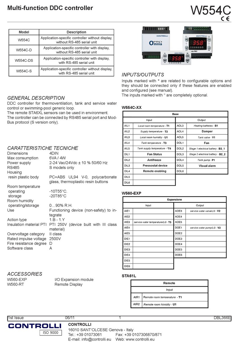
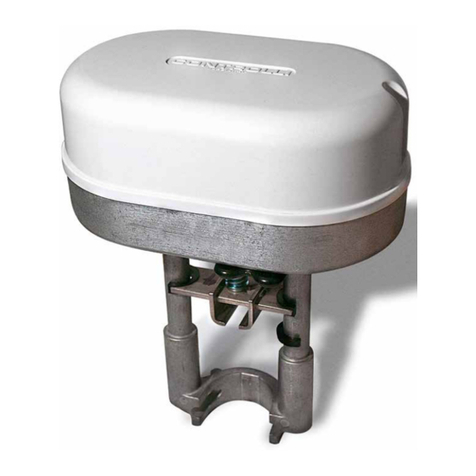
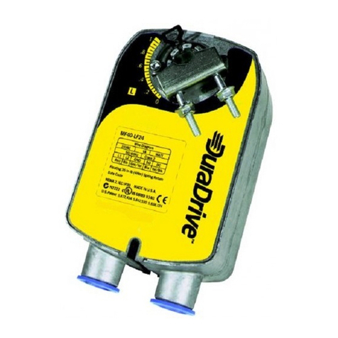
  9. Controlli MVC503R User manual

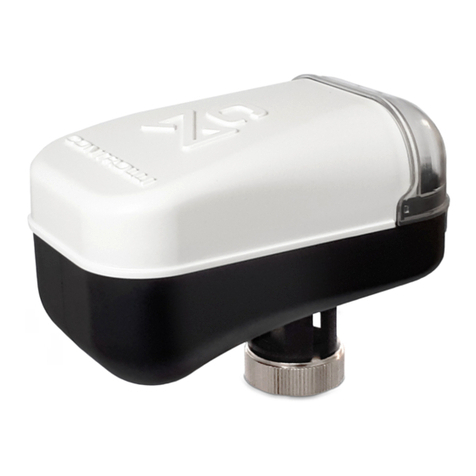
Controlli MVC503R User manual

CONTROLLI S.p.A. - 16010 Sant’Olcese (GE) - Italy
Tel. +39 010 73061 | Fax +39 010 7306870/871
[email protected] | www.controlli.eu
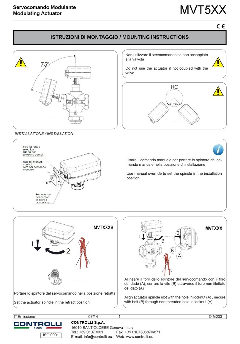
ISTRUZIONI DI MONTAGGIO / MOUNTING INSTRUCTIONS
Servocomandi con funzione di ritorno in emergenza
Actuator with electronic emergency return MVC503R
Non utilizzare il servocomando se non accoppiato alla
valvola
Do not use the actuator if not coupled with the valve
Portare lo spintore del servocomando nella
posizione retratta
Set the actuator spindle in the retract position
VSB.T-VMB.T, 2-3TGB.B, 2-3TBB.T, 2TGA.BTLibra, V.XT, VSXT.PBP, VSBT.-VMBT.
Allineare il foro dello spintore del servocomando con il foro
del dado (A), serrare la vite (B) attraverso il foro non lettato
del dato (A)
Align actuator spindle slot with the hole in locknut (A) , se-
cure with bolt (B) through non threaded hole in locknut (A)
1aEmissione / 1st Issue rev. a 09/19 1 DIM299
1
2
A
B
1
2
3
75°
NO
YES
1
2
A
B
1
2
3
75°
NO
YES
INSTALLAZIONE / INSTALLATION
AVVERTENZE In caso di accoppiamento di MVC su una
valvola prodotta prima di Settembre 2019 in sostituzione
di un MVT occorre utilizzare il kit 55061.
VALVOLA (PRODUZIONE PRECEDENTE SETTEMBRE 2019) /
VALVE (PRODUCTION PREVIOUS SEPTEMBER 2019)
SERVOCOMANDO DA SOSTITUIRE /
ACTUATOR TO BE REPLACED
KIT DI SOSTITUZIONE /
REPLACEMENT KIT
VSB.T-VMB.T MVT203
MVT403
MVT503
550612-3TBB.T
2-3TGB.B
WARNING In case of MVC coupling on a valve produced
before September 2019 to replace an MVT, must be used
the 55061 kit.
NO
SI
YES
75°
SELEZIONE DIP SWITCH / DIP SWITCHES SELECTION
Blu
Bianco/White
Rosso/Red
Verde/Green
Giallo/Yellow
+
-
Segnale/Signal
+
-
Feed back
24Vac/Vdc
-
+
SCHEMI DI COLLEGAMENTO / WIRING DIAGRAMS
Il servocomando viene fornito con
predisposizione per segnale di co-
mando 0...10 V- azione diretta e posi-
zione di ritorno completamente esteso
(DOWN); per modicare l’impostazio-
ne operare come segue:
1. Rimuovere la vite ed aprire il
coperchio trasparente come
indicato in gura.
2. Commutare i DIP secondo lo
schema seguente.
3. Le nuove impostazioni saranno
attive al prossimo ciclo di spegni-
mento/accesnsione.
L’attuatore può essere accoppiato a valvole CONTROLLI tira/spingi
utilizzando l’autoapprendimento della corsa (DIP 4 OFF), oppure
a valvole CONTROLLI con molla di ritorno utilizzando la corsa ssa
(DIP 4 ON).
The actuator is supplied prearranged
for 0-10V control signal, direct action
and fully extended return position
(DOWN); to modify this setting, follow
these instructions:
1. Remove the cover and the con-
nector (look at the following
picture).
2. Change the DIP switches as indi-
cated in the following scheme.
3. The new settings will be active on
the next power off/on cycle.
The actuator can be coupled with push/pull CONTROLLI valves using
auto calibration stroke; or to CONTROLLI valves with spring return
using xed stroke. Actuators with xed stroke (DIP 4 ON) have only
reverse action.
DIP ON OFF
1 Azione INVERSA / Reverse action Azione DIRETTA / Direct action
2 2-10 V / 6-10 V 0-10 V / 0-5 V
3 Campi SEQ / Range SEQ Campi NORM / Range NORM
4Corsa ssa / Fixed stroke Corsa auto / Auto calibrated stroke
5 4-20 mA Campi in tensione / DC Voltage range
6Apprendimento corsa / Corsa ssa
Calibration/Fixed stroke Corsa ssa / Fixed stroke
7 Ritorno in emergenza UP / Emergency position UP Ritorno in emergenza DOWN / Emergency position DOWN
8Corsa ssa / Fixed stroke selection Corsa ssa / Fixed stroke selection
9Corsa ssa / Fixed stroke selection Corsa ssa / Fixed stroke selection
1aEmissione / 1st Issue rev. a 09/19 2 DIM299
VALVOLE SENZA MOLLA / VALVES WITHOUT SPRING VALVOLE CON MOLLA / VALVES WITH SPRING
VSB.T-VMB.T
3/4” .. 2”
CORSA/STROKE
5,5 mm
2-3TGB.B
1/2”
CORSA/STROKE
11,5 mm
2-3TBB.T
1/2” .. 2"
CORSA/STROKE
12 mm
2TGA.BT
3/4” .. 2"
CORSA/STROKE
8,5 mm
VALVOLE ALTRI
COSTRUTTORI /
VALVES OF OTHER
MANUFACTURERS
CORSA/STROKE max
12 mm
VLX-VLX.P
3/4” .. 1 ¼”
CORSA/STROKE
4 mm
VSXT-VMXT-VTXT
1/2” .. 3/4”
CORSA/STROKE
5,5 mm
VSXT.PBP
1 ½”
CORSA/STROKE
5,5 mm
VSBT.-VMBT.
3/4” .. 2"
CORSA/STROKE
8,5 mm
MODELLO /
MODEL
MVC503R AG74-03 AG74-03
DIP 6 DIP 8 DIP 9 CORSA VALVOLA /
VALVE STROKE [mm]
OFF OFF OFF 2,5
OFF OFF ON 3
OFF ON OFF 3,5
OFF ON ON 4
ON OFF OFF 4,5
ON OFF ON 5
ON ON OFF 5,5
ON ON ON 6,5
Azione Diretta e Inversa
Attraverso il DIP 1 è possibile impostare il servocomando in azione
diretta (DIP1 in OFF) o inversa (DIP 1 in ON). In azione diretta e senza
segnale di comando la posizione dello spintore è verso l’alto (spin-
tore retratto) con uscita feedback a 2 V, mentre in azione inversa
e senza segnale di comando la posizione dello spintore è verso il
basso con feedback 2 V.
Impostazione Campi Segnale di Comando
Attraverso i DIP 2, 3 e 5 è possibile impostare 5 diversi campi di
ingresso.
Se il DIP 5 è in ON, il campo di ingresso è settato su 4-20 mA e i DIP
2 e 3 perdono signicato.
Se il DIP 5 è in OFF, i campi gestiti sono: 0-10/2-10 con DIP 3 in OFF,
0-5/6-10 con DIP 3 in ON.
Posizionamento iniziale
Viene eseguito ogni volta che l’attuatore viene alimentato e prima
di aver eseguito l’apprendimento della corsa. Questa operazione
permette al servocomando di partire da una posizione certa per
poi seguire il segnale di comando. Tale posizione dipende dalla
selezione effettuata sul DIP 1 (DIP 4 in OFF).
Funzione Stallo inatteso
Se viene riconosciuto un impuntamento nella corsa, questa funzione
ha lo scopo di sbloccarlo; l’attuatore verrà comandato in direzione
opposta per poi riprovare a raggiungere la posizione e verranno
eseguiti 3 tentativi.
Nel caso non si fosse sbloccato dopo i primi 3 tentativi, dopo una
pausa di 1 minuto vengono eseguiti ulteriori 3 tentativi.
Uscita feedback (2-10 V)
Il servocomando dispone di un’uscita dedicata per fornire il segnale
di feedback della posizione presunta dell’attuatore. Questo segnale
può variare da 2 a 10 V.
Durante la fase di “Apprendimento corsa” e “Posizionamento inizia-
le” il segnale rimane sso a 2 V.
Durante la fase di ritorno in emergenza il segnale di feedback
rimane sso a 1 V.
Comando manuale
Per azionare il comando manuale rimuovere l’alimentazione, rimuo-
vere il coperchio trasparente e inserire una chiave esagonale da
3 mm nel foro frontale e ruotare la chiave sino a quando non si è
raggiunta la posizione desiderata.
Direct/Reverse action
Through DIP1 is possible to set direct or reverse action. In direct action
without control signal the actuator is fully retracted with feedback
set to 2 V. With reverse action the actuator is fully exteded and the
feedback without control signal is 2 V in this position.
Setting Control Signal Fields
Through DIP 2, 3 and 5 it is possible to set 5 different input ranges.
If DIP 5 is ON, the input range is set at 4-20 mA and DIP 2 and 3 have
no meaning.
If DIP 5 is OFF, the possible ranges are: 0-10/2-10 if DIP 3 is OFF and
0-5/6-10 if DIP 3 is ON.
Initial Positioning
It is executed every time the actuator is powered and before to
have performed the learning of the race. This operation allows
the servocontrol to start from a certain position for then follow the
command signal. This position depends on the selection made on
DIP 1 (DIP 4 in OFF).
Unexpected stall condition
If an unexpected stop during the stroke occurs, this function has the
aim to make it disappear. The actuator will be driven in the opposite
direction and then it will try again to reach the position. 3 attempts
will be performed.
If it was not unlocked afte r the rst 3 at tempts, after a 1 mi nute pa use,
3 more attempts are made.
Feedback output signal (2-10 V)
The actuator is equipped with a proper output to transmit the feed-
back signal relating to the supposed actuator position. This signal
can vary from 2 to 10 V.
During the “automatic stroke calibration” and “Initial positioning”
function it is set at 2 V.
During the emergency positioning function the feedback signal is
set to 1 V.
Manual control
To operate the manual control, remove the power supply, remove
the transparent cover and insert a 3 mm hexagonal key into the front
hole and turn the key until the desired position is reached.
Apprendimento corsa (valido solo se DIP 4 è OFF)
Questa funzione consiste nell’apprendere il tempo massimo di corsa
della valvola a cui il servocomando viene accoppiato, in modo da
poterla posizionare correttamente seguendo il segnale di comando.
Con attuatore alimentato è ripetibile ogni volta che il DIP 6 va da
OFF a ON e il DIP 4 è OFF.
Impostazione corsa ssa
Attraverso il DIP 4 viene scelto (in base alla valvola accoppiata) se
la corsa deve essere ssa o appresa automaticamente. Nel caso di
corsa ssa (DIP 4 ON) la funzione di apprendimento (DIP 6) cambia
signicato in quanto in combinazione con DIP 8 e DIP 9 saranno usati
per scegliere il valore della corsa ssa (vedi tabella).
Calibration (valid only with DIP 4 OFF)
This function helps to calibrate the maximum valve time stroke, so
that the actuator can place the valve correctly following the con-
trol signal.
If the actuator is powered on, this action can be repeated any time
DIP 6 goes from OFF to ON and DIP 4 is OFF.
Fixed stroke setting
Through DIP 4 you can choose (on the basis of the coupled valve) if
the stroke must be xed or automatically calibrated. In case of xed
stroke (DIP 4 ON) the learning function (DIP 6) change its meaning:
DIP 8 and 9 will be used to choose the xed stroke value (look at
the table).
1aEmissione / 1st Issue rev. a 09/19 3 DIM299
Le caratteristiche contenute in questa pubblicazione possono essere modifi cate senza preavviso
The performances stated in this sheet can be modifi ed without any prior notice
FUNZIONAMENTO LED / LED BEHAVIOUR
Descrizione / Description DL1 (rosso / red) DL2 (verde / green) DL3 (giallo / yellow)
Fase di apprendimento / Cali-
bration Alternato / Alternate blinking 5 Hz ON
Posizionamento iniziale / Initial
positioning Alternato / Alternate blinking 1 Hz ON
Posizionamento UP / Running UP OFF Lampeggiante / Blinking 1 Hz ON
Fine corsa UP / End of stroke UP OFF ON ON
Posizionamento DOWN / Running
DOWN Blinking 1 Hz OFF ON
Fine corsa DOWN / End of stroke
DOWN ON OFF ON
Servocomando fermo / Holding OFF OFF ON
Stallo inatteso / Unexpected stall Contemporaneo / Solid 5 Hz ON
Tensione di alimentazione bassa /
Low voltage power supply OFF OFF Lampeggiante / Blinking 1 Hz
Tensione di alimentazione alta /
High voltage power supply OFF OFF Lampeggiante / Blinking 5 Hz
Corsa sotto minimo / Calibrated
stroke lower than minimum Lampeggiante / Blinking 1 Hz ON ON
Corsa sopra il massimo / Calibra-
ted stroke higher than max ON Lampeggiante / Blinking 1 Hz ON
Extra corsa / Extra stroke Lampeggiante / Blinking 5 Hz OFF ON
Servocomando spento o ne
ricarica supercap /Actuator OFF
or end of supercap charging
OFF OFF OFF
Ritorno in emergenza / Emer-
gency positioning Contemporaneo / Solid 1 Hz OFF
Fase di ricarica dei supercap /
Supercap charging phase ON ON ON
DL1 DL2 DL3
Il dispositivo contiene componenti elettrici ed elettronici e non può essere smaltito con i riuti domestici. Vanno rispettate le normative locali sullo smal-
timento.
The device contains electrical and electronic components and is not allowed to be disposed of as household refuse. All locally valid regulations and
requirements must be observed.
1aEmissione / 1st Issue rev. a 09/19 4 DIM299
FORO COMANDO MANUALE ACCESSIBILE SOLO RIMUOVENDO IL COPERCHIO TRASPARENTE /
MANUAL CONTROL HOLE ACCESSIBLE ONLY REMOVING THE TRANSPARENT LID

Other Controlli Controllers manuals

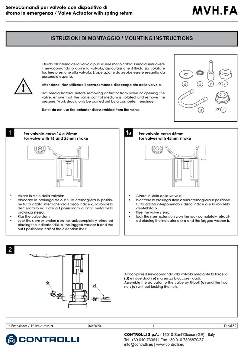
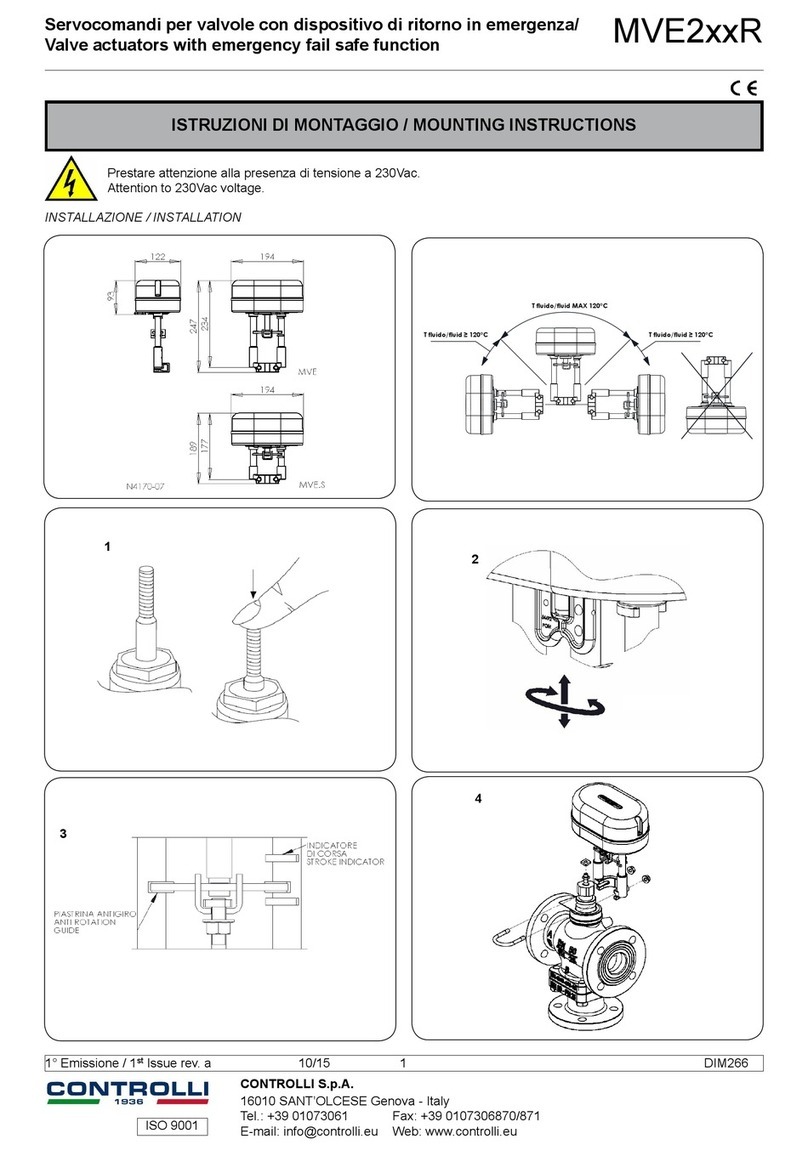
Controlli MVE2 R Series User manual

Controlli

Controlli MVE2 R Series User manual

Controlli Energon User manual

Controlli

Controlli Energon User manual

Controlli MVH56EA User manual

Controlli

Controlli MVH56EA User manual

Controlli MVE522 User manual

Controlli

Controlli MVE522 User manual

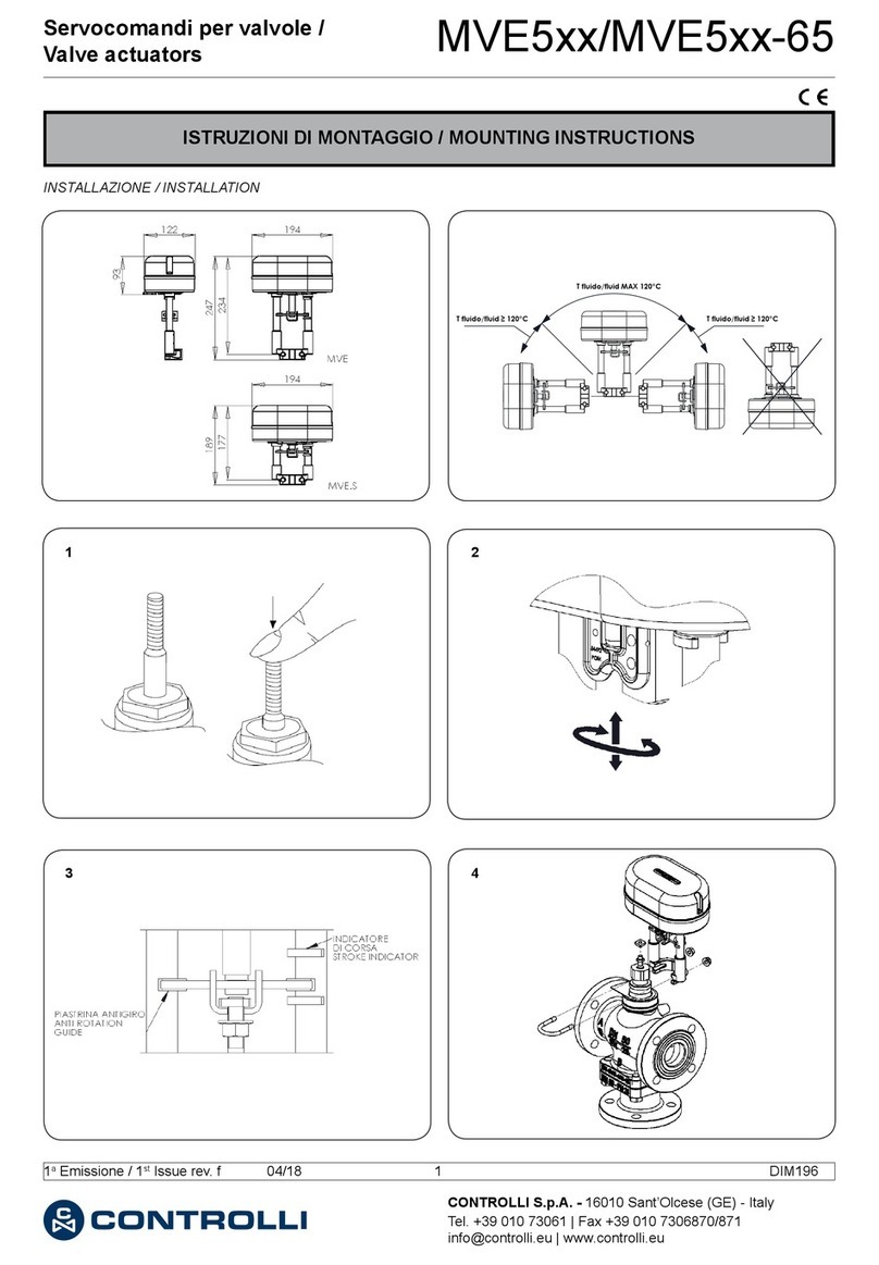
Controlli MVE5-65 Series User manual

Controlli

Controlli MVE5-65 Series User manual

Controlli MVT5 Series User manual

Controlli

Controlli MVT5 Series User manual

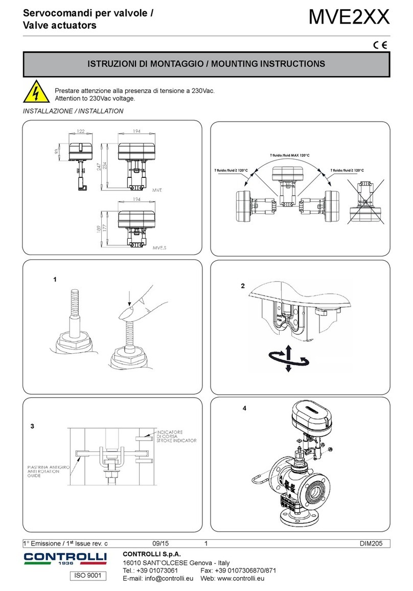
Controlli MVE2 Series User manual

Controlli

Controlli MVE2 Series User manual

Controlli MVC503R-MB User manual

Controlli

Controlli MVC503R-MB User manual

Controlli NR9000 User manual

Controlli

Controlli NR9000 User manual

Controlli W554C User manual

Controlli

Controlli W554C User manual

Controlli NR9003 User manual

Controlli

Controlli NR9003 User manual

Controlli MVE2 R Series User manual

Controlli

Controlli MVE2 R Series User manual

Controlli NR9003 User manual

Controlli

Controlli NR9003 User manual

Controlli Energon NR9001 User manual

Controlli

Controlli Energon NR9001 User manual

Controlli MVH56E User manual

Controlli

Controlli MVH56E User manual

Controlli MVE2 R-65 Series User manual

Controlli

Controlli MVE2 R-65 Series User manual

Controlli MVH User manual

Controlli

Controlli MVH User manual

Controlli MVE506 User manual

Controlli

Controlli MVE506 User manual

Controlli MVE522-65 User manual

Controlli

Controlli MVE522-65 User manual

Controlli MDL Series User manual

Controlli

Controlli MDL Series User manual

Controlli MVE2 Series User manual

Controlli

Controlli MVE2 Series User manual

Controlli MVH56EX User manual

Controlli

Controlli MVH56EX User manual

Controlli MVB2 Series User manual

Controlli

Controlli MVB2 Series User manual

Controlli MVB User manual

Controlli

Controlli MVB User manual

Popular Controllers manuals by other brands

Elimko E-70-O user manual

Elimko

Elimko E-70-O user manual

GESTRA LRR 1-60 Original Installation & Operating Manual

GESTRA

GESTRA LRR 1-60 Original Installation & Operating Manual

WEST P8700 user guide

WEST

WEST P8700 user guide

Rockwell Automation Allen-Bradley 1756 ControlLogix Programming manual

Rockwell Automation

Rockwell Automation Allen-Bradley 1756 ControlLogix Programming manual

Reloop Mixtour Quick start guides

Reloop

Reloop Mixtour Quick start guides

KIOUR REF-FA3 V2 quick start guide

KIOUR

KIOUR REF-FA3 V2 quick start guide

Rotex RoCon UFH operating instructions

Rotex

Rotex RoCon UFH operating instructions

Nice One-Max Installation and use instructions and warnings

Nice

Nice One-Max Installation and use instructions and warnings

ABB AC 800F Engineering manual

ABB

ABB AC 800F Engineering manual

Danfoss EKC 202C-MS instructions

Danfoss

Danfoss EKC 202C-MS instructions

Graco 311595C Instructions - parts

Graco

Graco 311595C Instructions - parts

DROPLUX HX-DLV004-RFBK Product introduction

DROPLUX

DROPLUX HX-DLV004-RFBK Product introduction

Bryant Evolution Connex SYSTXBBECW01 Installation & quick start guide

Bryant

Bryant Evolution Connex SYSTXBBECW01 Installation & quick start guide

Axis A1610 installation guide

Axis

Axis A1610 installation guide

Murphy iGUARD AL-02058B Specifications

Murphy

Murphy iGUARD AL-02058B Specifications

PPM CR3551 Handbook

PPM

PPM CR3551 Handbook

Conductix-Wampfler 80 Series manual

Conductix-Wampfler

Conductix-Wampfler 80 Series manual

Mold-Masters TempMaster M1 Plus Series user manual

Mold-Masters

Mold-Masters TempMaster M1 Plus Series user manual

manuals.online logo
manuals.online logoBrands
  • About & Mission
  • Contact us
  • Privacy Policy
  • Terms and Conditions

Copyright 2025 Manuals.Online. All Rights Reserved.