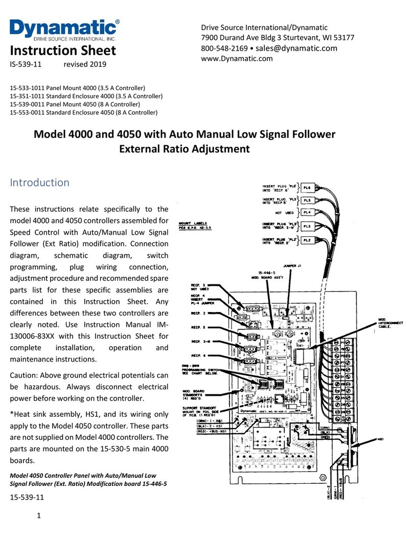
Dynamatic 4050 User manual

1
Instruction Sheet
IS-539-09 revised 2019
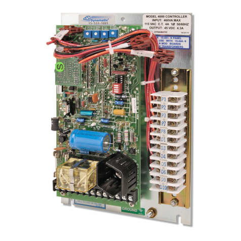
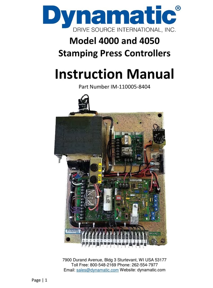
15-533-1009 Panel Mount 4000 (4.3 A Controller)
15-551-1009 Standard Enclosure 4000 (4.3 A Controller)
15-539-0009 Panel Mount 4050 (8 A Controller)
15-553-0009 Standard Enclosure 4050 (8 A Controller)
Model 4000 and 4050 with Auto Manual Tach Follower
Introduction
These instructions relate specifically to
the following Model 4000 and 4050
controllers which are assembled for
Speed Control with the Auto Manual Tach
Follower Modification.
Connection diagram, schematic diagram,
switch programming, plug wiring
connection, adjustment procedure and
recommended spare parts list for these
specific assemblies are contained in this
instruction sheet. Any differences
between these two controllers are clearly
noted.
Use instruction manual IM-130006-83-XX
with this instruction sheet for complete
installation, operation and maintenance
instructions.
Caution: Above ground potentials can be
hazardous. Always disconnect electrical
power before working on the controller.
*Heat sink assembly, HS1, and its wiring
apply only to the Model 4050 controllers.
These parts are not supplied on the Model
4000 controllers. The parts are mounted
on the 15-530-5 main 4000 board.
Drive Source International/Dynamatic
7900 Durand Ave Bldg 3 Sturtevant, WI 53177
www.Dynamatic.com

2
Introduction............................................................................................................................................. 1
Connection Diagram for Standard Enclosure 4000 Controller ...............................................................3
Schematic Diagram for 4000 controller..................................................................................................4
Connection Diagram for 4000 Panel Mount and 4050 Controllers ........................................................5
Schematic Diagram for 4050 controller..................................................................................................6
Tach Follower PCB 15-444-1...................................................................................................................6
General Description ................................................................................................................................. 7
Visual Inspection...................................................................................................................................... 7
Preliminary Adjustments.......................................................................................................................... 7
1. Operator Controls................................................................................................................................7
2. Main PCB 15-530-5 or 15-530-6 ..........................................................................................................7
Trimpot Illustration.................................................................................................................................8
3. Tach Follower Mod PCB 15-444-1 .......................................................................................................8
Adjustment Procedure ............................................................................................................................. 8
3. Zero Adjust R19 with LED monitor ......................................................................................................9
Zero Adjust R19, Alternate Method- ......................................................................................................9
4. Max Speed/Volts R21- .........................................................................................................................9
Max Speed/Volts R21 with LED monitor ................................................................................................9
Max Speed/Volts R21, Alternate Methods...........................................................................................10
6. Time Constant (TC) Adjust R26..........................................................................................................10
7. Current Feedback R20*- ....................................................................................................................10
8. Accel Rate R18-..................................................................................................................................10
9. Velocity Damping R22*- ....................................................................................................................11
Renewal Parts List .................................................................................................................................. 12

3
Connection Diagram for Standard Enclosure 4000 Controller
ED-58209
Note 1: This equipment must be installed in compliance with National Electrical code and all applicable
state and local codes
Note 2: Transformer may be supplied as a winding in the ac motor or as a separate item. Standard
connections to winding in mechanical unit and to separate transformer are both above.
Note 3: Values shown are typical. See BOM for actual values.

4
Schematic Diagram for 4000 controller

5
Connection Diagram for 4000 Panel Mount and 4050 Controllers
ED/56809
See page 2 for notes and description of symbols

6
Schematic Diagram for 4050 controller
Tach Follower PCB 15-444-1

7
General Description
This modification allows a drive to follow the speed of another drive at some proportionate ratio, 1:1, 2:2
etc. This is accomplished by first producing a dc analog voltage of the master speed by rectifying and
filtering the output of the master ac tachometer generator. It is then divided with the ratio potentiometer
to produce a suitable reference for the follower. This is the Automatic Follower Mode.
The Follower drive can also be placed in a Manual Mode in which its speed is set by an external Manual
Speed Potentiometer. In this mode, Linear or Standard Acceleration can be selected.
Visual Inspection
1. Before proceeding to the preliminary adjustments, check the controller for any damage that may
have occurred during shipment, such as loose connections and damage wire or components.
2. Check all interconnecting wires for conformance to connection diagram and schematic as supplied
in this instruction sheet.
3. Check the Operator’s controls (which are supplied by customer) to see if they are connected
properly per the connection diagram. This includes the Manual Speed pot R5, the Ratio pot R55,
the Manual/Auto selector switch and the Start and Stop pushbutton controls.
Preliminary Adjustments
Perform the following preliminary adjustments (with no power applied to the controller).
1. Operator Controls (supplied by customer unless specified)
a. Set the Manual Speed potentiometer R5 to 0% (Full CCW)
b. Set the Auto/Manual selector switch to the Manual position
c. Set the Ratio pot R55 to 0% (Full CCW)
d. Note location of Start and Stop pushbuttons
2. Main PCB 15-530-5 or 15-530-6
The pots used are screwdriver adjust, single turn pots. Do not use a screwdriver with a blade width
exceeding 1/8 inch
a. Set the Accel Rate potentiometer R18 to 100% (Full CW)
b. Set the Zero Adjust potentiometer R19 to 0% (Full CCW)
c. Set the Max Speed/Volts potentiometer R21 to 0% (Full CCW)
d. Set the Velocity Damping potentiometer R22 as follows (See trimpot illustration)
e. Set the Time Constant (TC) Adjust potentiometer R26 as follows (see trimpot illustration)
f. Set the Current Feedback potentiometer R20 to 0% (Full CCW)

8
Mechanical Unit Model Numbers
Velocity
Damping
Setting
AC/ACM/ACS/PD/VT
Fractional Hp (FHP)
AS/AT/AE/VT/EC
Fractional HP
14/121/140
0%
181/182/184/186
18/21/132/160/180/210
50%
214/216/254/256
25/27/180/225/250/280
75%
280/320/360/440
320/360/440
75%
Mechanical Unit Model Numbers
TC Adjust
Setting
AC/ACM/ACS/PD/VT
Fractional Hp (FHP)
AS/AT/AE/VT/EC
FHP/181/182
0%
184/186/214
14/18/112/132/140/180
15%
216/254/256/280
21/160/210
30%
320/360/440
25/27/180/225/250/280
100%
320/360/440
100%
*Typical product number stamped on mechanical unit nameplate:
1. A1-100214-0053, specific mechanical model is AC-214
2. B2-100210-0008, specific mechanical model is AS-21
Trimpot Illustration
3. Tach Follower Mod PCB 15-444-1
a. Set the Max Ratio potentiometer R3 to 0% (Full CCW)
b. Set the programming switches and jumper as indicated in the controller programming chart
on the connection diagram
Adjustment Procedure
Caution: To avoid personal injury or damage to the test equipment remove before connecting or
disconnecting test equipment

9
The Model 4000 and 4050 controllers contain an LED status monitor which provides a visual means of
setting the maximum speed and minimum bias. This LED set up along with an alternate method is given
below.
1. Turn ON the power to the drive and start the ac motor.
2. Start the controller with the Start pushbutton. Note the location of the Stop pushbutton
3. Zero Adjust R19 with LED monitor- Slowly increase the Zero Adjust potentiometer r19 CW while
monitoring the LED, D22. When controller output is turned ON or clutch voltage is turned ON (or
the drive shaft begins to rotate), the LED should start flashing. Now just back off slowly until
flashing stops.
Zero Adjust R19, Alternate Method-This adjustment can be set to provide zero rpm or some
minimum speed greater than zero, as required by the machine operating requirements.
a. For zero rpm, turn the Zero Adjust potentiometer R19 CW until the output shaft just begins
to turn. Then, back off on the control until the output shaft just stops turning. Stop and start
the controller a few times to be sure the drive shaft does not rotate.
b. For a minimum speed greater than zero, the LED cannot be used. Turn the Zero Adjust
potentiometer CW until the desired speed is attained. For an accurate setting use a
tachometer or stroboscope.
4. Max Speed/Volts R21-This adjustment can be set to limit drive speed to its rated maximum or
to a slower speed as required by the machine process. An LED status monitor has been provided
on the main board to allow you to set the maximum speed without the use of a tachometer,
stroboscope or voltmeter. However, an alternate method of set up using this equipment is given
to set the maximum speed point. The tachometer or stroboscope will give an accurate rpm setting
while the use of a voltmeter will give only an approximate speed setting. This is because the
voltmeter is measuring generator voltage instead of actual output rpm.
Max Speed/Volts R21 with LED monitor- Set the Manual Speed potentiometer R5 at 100% (Full
CW). The drive should be loaded for best results. Set the Max Speed/Volts potentiometer R21 at
100% (Full CW) Caution: drive will go to top speed. The LED should be out when the drive is at top
speed. With the LED out, slowly turn the Max Speed/Volts potentiometer R21 CCW until the LED
lights. This indicates that the speed of the drive is in the regulating range of the controller. The
clutch voltage should drop below 45V. This will be approximately the maximum rated speed of
the drive. The maximum speed point setting will vary with different mechanical units.
There are two other conditions for which the LED will be out besides the drive being set for zero
speed or running wide open above the regulating range. These are whenever the “E” relay is
deenergized (the drive is stopped), or due to a wiring error, ground or some malfunction of the
controller itself.

10
Max Speed/Volts R21, Alternate Methods
a. To set maximum rated speed with a tach or stroboscope: turn the Manual Speed
potentiometer R5 to 100% (Full CW). Allow the drive to accelerate to full speed, turn the Max
Speed/Volts pot CW until the rated speed indicated is the same as the speed listed on the
nameplate of the mechanical unit.
b. To set approximate maximum speed with a voltmeter, connect a voltmeter (60 Vac scale)
across terminals G1 and G2. Turn the Manual Speed pot R5 to 100% (Full CW). Allow the drive
to accelerate to full speed, turn the Max Speed/Volts pot CW until the meter Reading ceases
to rise.
c. To set a maximum speed that is less than rated maximum speed requires the use of a
tachometer or stroboscope indicator. This cannot be accomplished with the LED status
monitor. Turn the Manual Speed Potentiometer to 100% (Full CW). Allow the drive to
accelerate to full speed, slowly increase Max Speed/Volts potentiometer setting CW until the
desired speed is indicated.
5. Since there may be some interaction between the Zero Adjust and the Max Speed/Volts,
particularly if the minimum speed is other than zero, repeat steps 3 and 4 until the desired speeds
are obtained for both the zero and max positions of the Manual Speed pot.
6. Time Constant (TC) Adjust R26. The TC Adjust is used to set current feedback by using coil
voltage and a variable RC combination to simulate the different coil time constants of various size
drives. A trimpot illustration is provided to facilitate the setting of this control. Sufficient range
has been provided for drive sizes from fractional through 20 hp for the 4000 controller and up to
125 hp for the 4050 controller. Set you TC control appropriately for your individual drive size as
shown in Preliminary Adjustments.
Setting are not critical and so may be “tuned” for each drive. High inertia applications can benefit
from a higher than normal setting.
7. Current Feedback R20*- Normal operation will not require use of this potentiometer. Certain
applications are best met with a negative current feedback response which is slower in settling
and less likely to overshoot at low rpms. There are some low inertia, light load, linear acceleration
applications that may also benefit from improved low-end linearity with current feedback
damping. If you have one of these applications, remove Jumper J1 from the Normal position and
place it in the Increased position. Adjust Current Feedback R20 as required to obtain desired drive
response.
*See basic 4000/4050 manual for a more detailed description of this adjustment.
8. Accel Rate R18-The purpose of Linear Acceleration is to slow down drive response to an increase
in command. Without Linear Accel control, the drive will respond to operator speed adjustments
very quickly, limited only by the torque capacity of the drive. With the Linear Accel circuit, the
output of the controller is linear with respect to time. This circuit is adjustable from 3 to 90
seconds. The controller output will go through Linear Acceleration in the Manual mode only.
When set at the slowest acceleration rate, the drive will take 90 seconds to accelerate from zero
11
to rated speed, following a linear ramp. When less than rated speeds set, this time required to
reach top speed is proportionally less.
The Linear Acceleration circuit may be activated or deactivated in the Manual mode by setting
the programming switches as indicated on the programming chart on the connection diagram.
To set the Accel Rate: stop the controller with the Stop pushbutton. Turn the Manual Speed
potentiometer to 100% (Full CW). With the drive at a complete stop, push the Start pushbutton
and time the interval required for the drive to accelerate from zero to full speed. Adjust the Accel
Rate potentiometer R18 CCW for a slower accel rate, or CW for a faster accel rate.
Note: Only the Acceleration Rate is adjustable. The response of the controller to a reduced
command is instantaneous. The response of the drive to a decrease in command is a function of
drive system load and inertia.
9. Velocity Damping R22*-This potentiometer is used to match the controller response to the
drive response (drive response is a function of the clutch coil time constant and system inertia)
The proper setting for this adjustment depends on the drive size and total load inertia. See
Preliminary Adjustments. If instability (speed control becomes erratic) occurs at any setting
increase (turn CW) slightly until the speed becomes stable.
*See basic 4000/4050 manual for a more detailed description of this adjustment
10. Set the Manual/Auto switch to Auto. Set the Ratio pot to 100% (Full CW). Start the Master drive
and run at maximum line speed. Start the Model 4000 or 4050 Follower controller.
11. Use a tachometer, stroboscope or voltmeter to observe the speed of both the Master Drive and
the Follower Drive. Adjust the Max Ratio pot R3, on the modification PCB, to the desired maximum
Follower Drive speed. Do not exceed the maximum rated speed of the follower mechanical unit.
12. Reduce speed of the Master Drive to approximately 15% of its rated speed. Measure the speed
of both drives and adjust the Follower Drive’s Zero Adjust pot to match speeds.
13. Repeat steps 11 and 12 until the desired tracking is obtained.
14. To run the Follower Drive at a percentage of the Master Drive Ratio pot for the desired percentage
(follower Drive Man/Auto switch must be in the Auto position)
15. For independent Speed control of the Follower Drive, place the selector switch in Manual and use
the Follower Drive Manual Speed pot.
16. Check motor current to make sure the motor is operating within its rating. If motor current
exceeds the nameplate rating, shut it down and correct the problem. This completes the
adjustment procedure.

12
Renewal Parts List for Standard 4000 & 4050 Controllers with Manual/Auto Tachometer Follower
Qty
Part Number
Description
Legend
Model 4000 Controllers
15-530-0005 Main PCB Assembly **
1
27-123-0001
Mini-Jumper
J1
*2
32-018-4091
Fuse, 4 Amp, 250 V
FU1, 2
*1
53-398-0001
Relay, 4pdt, plug-in
E
15-533-1009 Panel Mount
1
15-530-0005
Main PCB (Refer to PCB parts list above)
*1
15-444-0001
Tach Follower PCB assembly
4
36-298-0010
Circuit board support
15-551-1009 Standard Enclosure
1
15-530-5
Main PCB (Refer to PCB parts list above)
*1
15-446-0001
Tach Follower PCB assembly
4
36-298-0010
Circuit board support
Model 4050 Controllers
15-530-0006 Main PCB Assembly **
1
27-123-0001
Mini Jumper
J1
*2
32-028-0100
Fuse, 10 Amp, 250 V
FU1, 2
*1
53-398-0001
Relay, 4pdt, plug-in
E
15-539-0009 Panel Mount
1
15-530-0006
Main PCB (Refer to PCB parts list above)
*1
15-444-0001
Tach Follower
1
15-529-0019
Heat sink assembly, incl. Q1 & D3
4
36-298-0010
Circuit board support
15-553-9 Standard Enclosure
1
15-539-9
Basic Panel assembly (Refer to Panel Mount parts list
above)
*Denotes minimum spare parts **Denotes suggested spares when downtime is critical

13
Drive Source International/Dynamatic
7900 Durand Ave Bldg 3 Sturtevant, WI 53177
www.Dynamatic.com
Other manuals for 4050
2
This manual suits for next models
1
Table of contents
Other Dynamatic Controllers manuals

Dynamatic
Dynamatic EC 2000-CES User manual

Dynamatic
Dynamatic 4000 User manual

Dynamatic
Dynamatic 4050 User manual

Dynamatic
Dynamatic CES User manual

Dynamatic
Dynamatic 4050 User manual

Dynamatic
Dynamatic EC 2000 User manual

Dynamatic
Dynamatic 4000 User manual

Dynamatic
Dynamatic 4000 User manual

Dynamatic
Dynamatic 4000 User manual