neutral labs SCRAT v1.1 User manual

SCRAT v1.1
by neutral labs
Build Guide
Important!
DO NOT EMPTY ANY OF THE COMPONENT BAGS NOW! The components are grouped
into the bags so that all of them can be identified without having to
look up resistor ring codes or inspect diodes with aloupe. Rather
leave everything inside the bags and take out what you need while
soldering. This way you will not have to use resistor ring codes or a
multimeter to determine the values.

Component List
Part
Count
Type
Polarity
matters?
C1-C4
4
electrolytic capacitor 0.1 µF
yes
C5-C6
2
ceramic capacitor 3.3 nF
no
C7-C9
3
electrolytic capacitor 10 µF
yes
D1-D4
4
BAT85 Schottky diode
yes
D5-D6
2
1N4148 signal diode
yes
D7
1
LED orange 3 mm
yes
J1-J4
4
Thonkiconn mono 3.5 mm switching jack
-
J5-J6
2
5-pin header (panel port)
no
J7
1
Eurorack 10-pin power header
no
OK1-OK2
2
H11F1M analog FET optocoupler + DIP6 socket
yes
Q1
1
transistor J175 P-Channel JFET
yes
R1-R3
3
10 kΩ
no
R4-R8
5
100 kΩ
no
R9-R10
2
100 Ω
no
R11-R12
2
4.7 kΩ
no
R13-R19
7
1 kΩ
no
R20-R23
4
2.2 kΩ
no
RV1-RV4
4
10 kΩlinear potentiometer
-
SW1-SW3
3
SPDT switch
no
U1
1
TL074 quad op-amp and DIP14 socket
yes
XX
-
various sample components to be used with
the panel ports of the completed module
These do not go on the PCB!
-

Step-by-step instructions
Solder the diodes D1-D6 (except D7!) and all resistors first
(R1-R23). You do NOT have to read ring codes or use amultimeter to
determine the resistor values. Neither do you have to use aloupe to
inspect the labels on the diodes. There are only unique sets, so you
can just count the ones in each set to find out the value. Some of
the resistors in your kit may be white, green or blue instead of
beige. Don’t worry, they all work pretty much the same.
Caution! Polarity matters for diodes. The black line on each diode
must match the white line on the PCB.In case of reversed polarity,
you may damage your module when plugging it in!

Next, put in the IC sockets (U1 and OK1-OK2). They have alittle
notch on one side which should match the notch of the white outline
on the PCB. (It’s not harmful if you put one in the other way around
by accident, as long as you make sure the IC is facing the right way
when you plug it in later.)
An easy way to solder these sockets is to set them into the PCB
holes, put the front panel or apiece of cardboard flat on top and
flip the whole thing over. Alternatively, use some sticky tape to
hold it in place. Solder asingle corner pin and then the opposite
corner pin –now you can remove the tape, front panel or cardboard
and freely move the PCB to solder the rest of the pins.
Put in the 0.1 µF capacitors now (C1-C4). Caution! Polarity matters
for all of the electrolytic capacitors. Their longer leg goes on the
plus side as indicated on the PCB.
The solder pads for the small capacitors are quite close to each
other, so make sure there’s no accidental solder bridge between them,
or you might damage the module when plugging it in. It helps to bend
the capacitor’s legs slightly outward before soldering. Test
connectivity with a multimeter if you are unsure.

Put in the small 3.3 nF capacitors next (C5-C6, polarity does not
matter for them). In your kit, C5 and C6 may be different in size,
shape and/or color from the ones shown here. Don’t worry, ceramic
capacitors come in different designs, but they work the same way.
Add the J175 JFET (Q1). Polarity matters for the JFET!Insert it
facing as indicated by the outline on the PCB.
Now add the 10 µF capacitors (C7-C9). Caution! Polarity matters for
C7-C9! Put in the 2x5 pin power header (J7). As with the IC socket,
it’s best to solder asingle pin first. You may want to hold the
headers in place with apiece of sticky tape while soldering. Another
trick is to plug the Eurorack power cable into the header before and
hold it this way.

Flip the PCB over. Now on to J5 and J6 (the panel port headers).
There are 2different types of DIY kits with different types of
headers. If your kit has headers with long legs that look like this,
skip the next step.
or
If your kit has two 5-pin precision headers with round holes and
short legs, put them into J5 and J6 as shown and solder them. They
are there in order to increase the overall height, so the panel port
headers will be flush with the front panel.

or
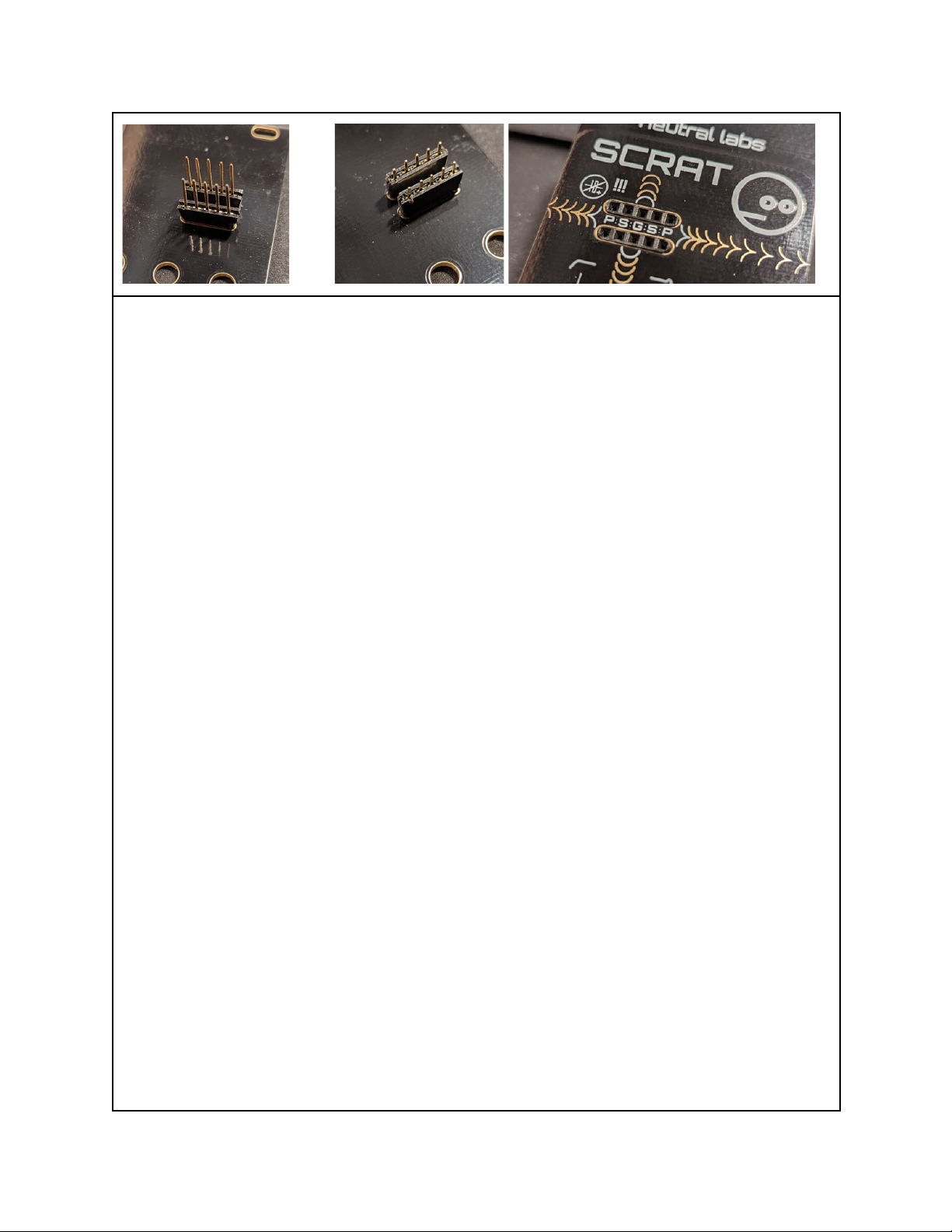
In case your kit has these 5-pin precision headers, it will also have
aregular 19-pin or 20-pin female header strip (with short legs).
Otherwise it will have two 5-pin headers with long legs.
Unless you have two individual 5-pin headers already, break two 5-pin
wide pieces from the longer header strip, you will need them for the
front panel ports. Splitting aheader is best done with awire cutter
or apair of pliers. Cut right along the position of apin and be
aware that you will lose that pin when breaking apart the headers.
The two 5-pin headers (with long or short legs depending on your kit)
must now be inserted into the two slots from the back of the front
panel. They should sit in there tight, flush with the front panel –
or protrude ever so slightly –and not wiggle! In order to achieve
this, you may want to use either afile, sandpaper or an X-Acto
knife, taking away bit by bit of plastic and rounding the short
edges. Be careful not to file, sand or cut into one of the 5square
holes that will be exposed on the front panel! Newer versions of the
kit have slightly wider slots, so no sanding or filing is needed.
Put in the orange LED (D7). Polarity matters: The short leg goes on
the negative (minus) side. Do not solder it in place yet!
Remove the nuts from the pots (RV1-RV4) and jacks (J1-J4). You may
want to clip the little silver anti-rotation tab off the pots with a
wirecutter. Remove the top nuts, knurled washers and anti-rotation
washers from the switches (SW1-SW3). Leave the bottom nut, but do not
tighten it: Give it about half aturn to one full turn from its
lowest position. Discard the anti-rotation washers.
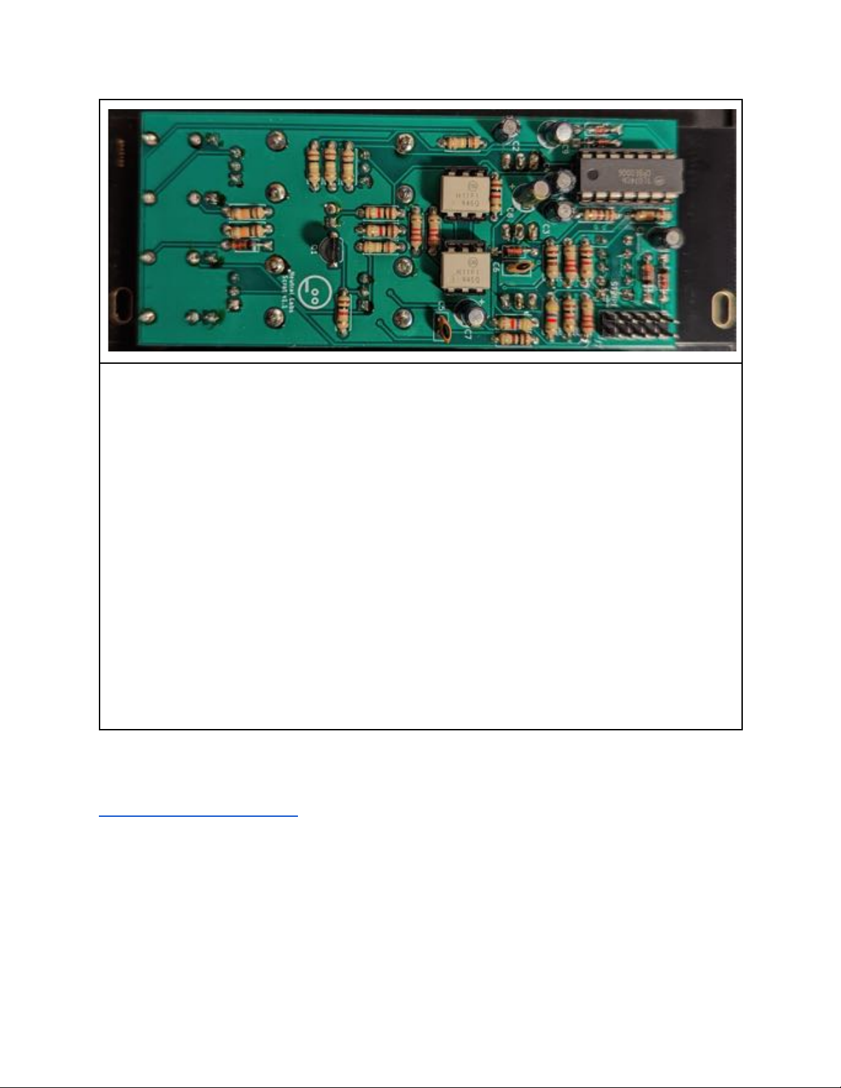
Fit the pots, switches and jacks onto the PCB without soldering yet.
Then put on the front panel. The headers inside the panel slots
should fit into the holes on the PCB (or the holes on the precision
headers if your kit has them). Add and lightly tighten all the nuts
to hold the panel in place. Carefully flip everything back over and
solder. Make sure the LED sticks out from the PCB to touch the panel.

Plug the ICs into their sockets (U1 and OK1-OK2). They have little
notches or dots on them, which should match the little notch on the
socket (and the notch in the white outline on the PCB). Bend their
legs slightly inward if you have trouble fitting them in.
Now plug in and test your module. Refer to the manual if needed.
If something’s not right, it may be best to unplug the module from
Eurorack power immediately so as not to damage it (or the PSU).
Most problems can easily be fixed by reheating all solder joints so
the solder can reflow. Also visually inspect joints and see if you
can spot accidental solder bridges.
When everything is working correctly, you can now tighten all the
nuts. If using awrench or pliers, be careful not to scratch the
front panel surface. As the final step, put the knobs on the pot
shafts.
If you need help troubleshooting or want to share photos, audio and/or
video of your creations (please do), send amessage to
Table of contents