NEUTRIK xirium pro Installation instructions manual
Mounting Guide
Certified for U-NII-3 ISM band
2017-07 V2
RX with Repeater module
Transmitter signal Identical audio signal
from two different
sources = redundancy
Repeater
signal
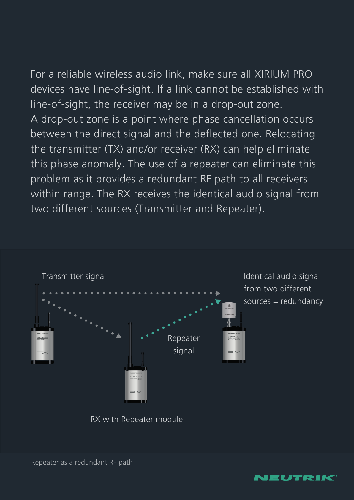
Repeater as a redundant RF path
Line-of-sight + redundant RF path
For a reliable wireless audio link, make sure all XIRIUM PRO
devices have line-of-sight. If a link cannot be established with
line-of-sight, the receiver may be in a drop-out zone.
A drop-out zone is a point where phase cancellation occurs
between the direct signal and the deflected one. Relocating
the transmitter (TX) and/or receiver (RX) can help eliminate
this phase anomaly. The use of a repeater can eliminate this
problem as it provides a redundant RF path to all receivers
within range. The RX receives the identical audio signal from
two different sources (Transmitter and Repeater).
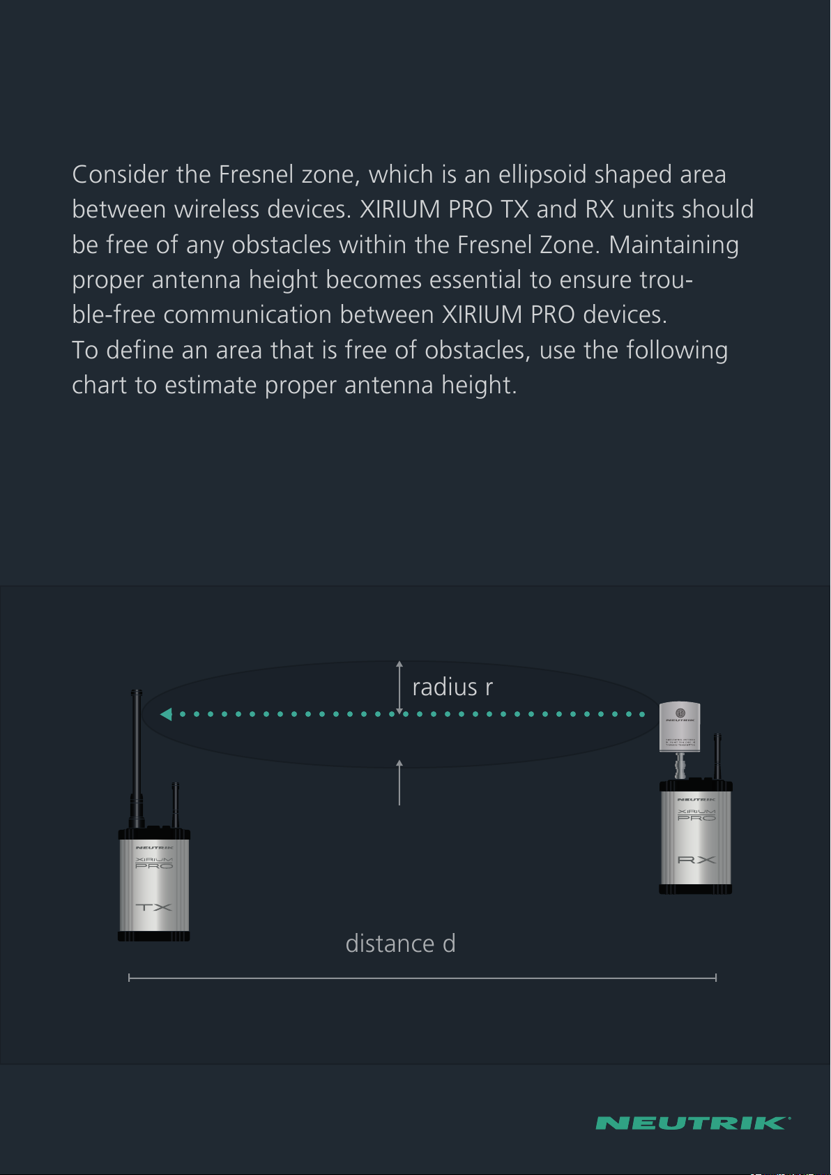
distance d
radius r
Fresnel zone
Antenna height + distance
Consider the Fresnel zone, which is an ellipsoid shaped area
between wireless devices. XIRIUM PRO TX and RX units should
be free of any obstacles within the Fresnel Zone. Maintaining
proper antenna height becomes essential to ensure trou-
ble-free communication between XIRIUM PRO devices.
To define an area that is free of obstacles, use the following
chart to estimate proper antenna height.
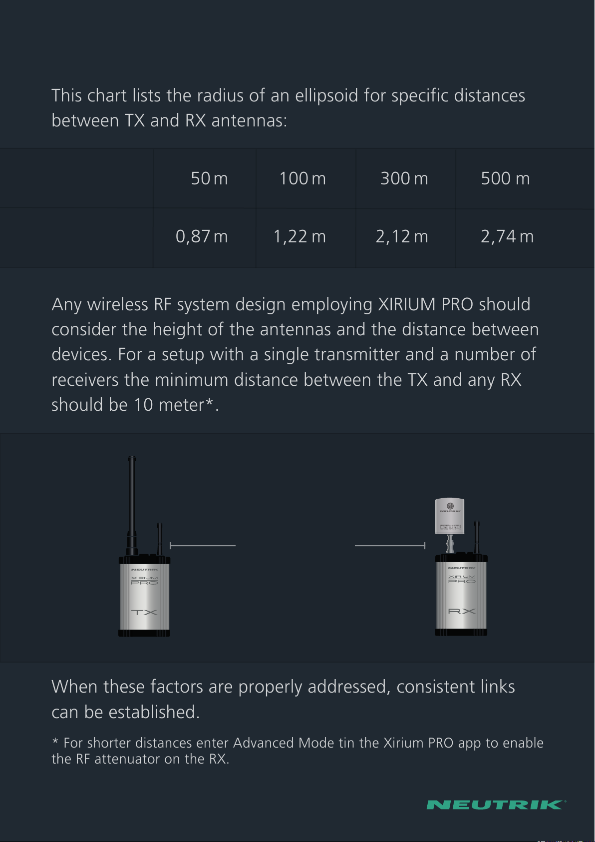
This chart lists the radius of an ellipsoid for specific distances
between TX and RX antennas:
distance d 50 m 100m 300 m 500 m
radius r 0,87m 1,22m 2,12m 2,74 m
Any wireless RF system design employing XIRIUM PRO should
consider the height of the antennas and the distance between
devices. For a setup with a single transmitter and a number of
receivers the minimum distance between the TX and any RX
should be 10 meter*.
* For shorter distances enter Advanced Mode tin the Xirium PRO app to enable
the RF attenuator on the RX.
When these factors are properly addressed, consistent links
can be established.
min. 10m*
NXPA-6-360-25 NXPA-14-40-35
25° vertical
360° horizontal
35° vertical
Antennas
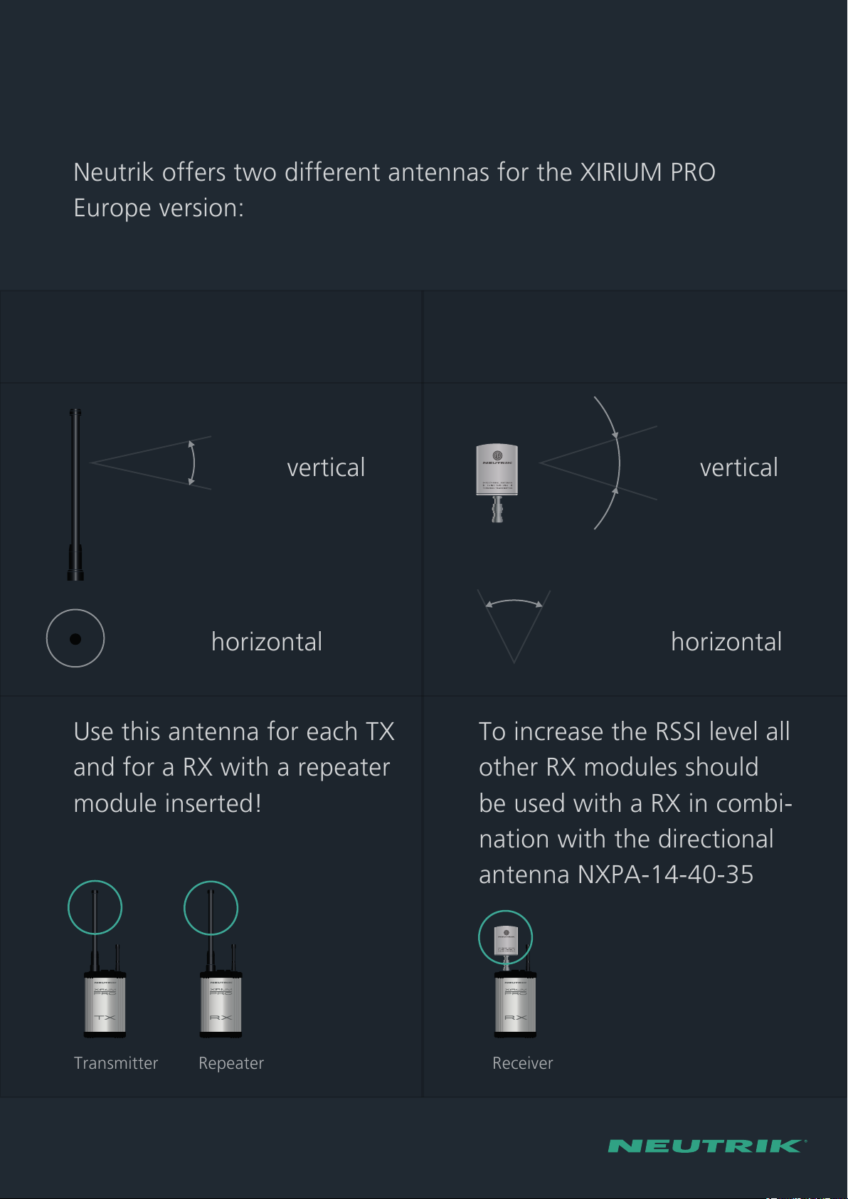
Neutrik offers two different antennas for the XIRIUM PRO
Europe version:
Use this antenna for each TX
and for a RX with a repeater
module inserted!
To increase the RSSI level all
other RX modules should
be used with a RX in combi-
nation with the directional
antenna NXPA-14-40-35
Any wireless RF system design employing XIRIUM PRO should
consider the height of the antennas and the distance between
devices. For a setup with a single transmitter and a number of
receivers the minimum distance between the TX and any RX
should be 10 meter*.
Transmitter
Receiver
Repeater
40° horizontal

NXPA-18-18-18
18° vertical
18° horizontal
Use this antenna in combination with an antenna cable (e.g.
Neutrik‘s NKXPA-5) as a remote antenna setup:
Due to RF regulations, directional antennas NXPA-14-40-35
and NXPA-18-18-18 may only be used with audio module
equipped receivers, not with repeaters or transmitters.
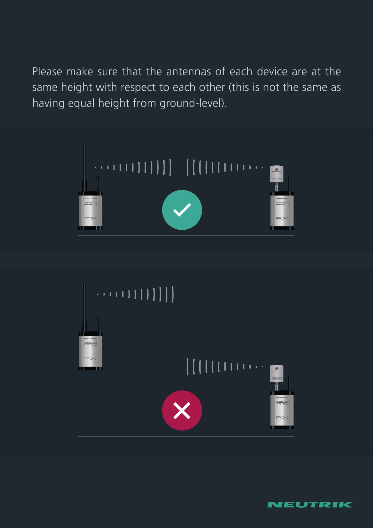
Please make sure that the antennas of each device are at the
same height with respect to each other (this is not the same as
having equal height from ground-level).

Here, antennas are shown at different heights, but are aligned
at the same angle with a clear line-of-sight.

-60
-28
-25
-80
OVERLOAD
LOW
Signal quality display
The Signal quality bar displays both RSSI level and packet
loss. The number of bars (left to right) refers to the RSSI level
(Received Signal Strength Indicator), whereas the color of the
bar meter displays the packet loss. Green bars indicate low
packet-loss, amber bars indicate moderate to bad packet
loss, and red bars indicate critical packet loss.
RSSI level should remain between the “low” and “overload”
areas. The colour of the bars should be green!
Good signal quality is not only measured by having the
highest RSSI level. It‘s more important to have low packet
loss (i.e. green bars). When necessary, engage the RX -30 dB
attenuater in the app by setting it to ON.
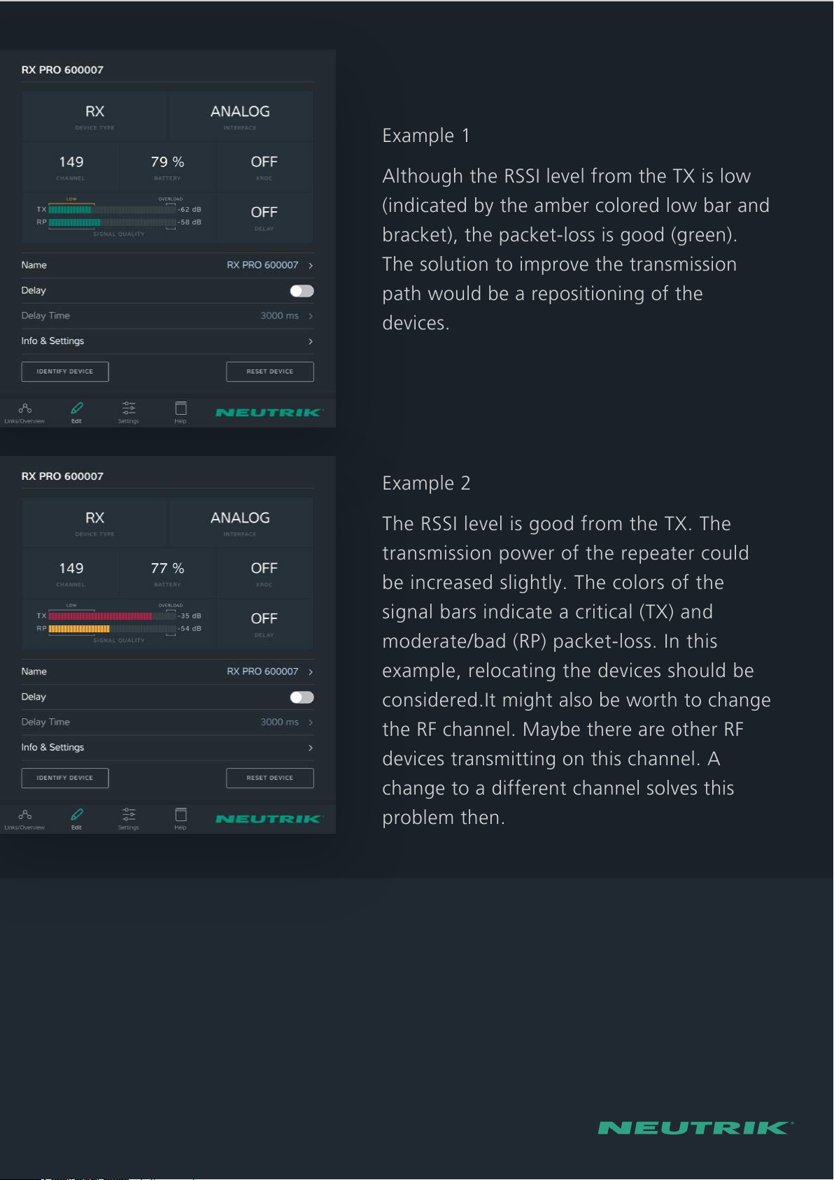
Example 1
Although the RSSI level from the TX is low
(indicated by the amber colored low bar and
bracket), the packet-loss is good (green).
The solution to improve the transmission
path would be a repositioning of the
devices.
Example 2
The RSSI level is good from the TX. The
transmission power of the repeater could
be increased slightly. The colors of the
signal bars indicate a critical (TX) and
moderate/bad (RP) packet-loss. In this
example, relocating the devices should be
considered.It might also be worth to change
the RF channel. Maybe there are other RF
devices transmitting on this channel. A
change to a different channel solves this
problem then.

-70
-28
-25
-80
OVERLOAD
LOW
XROC mode
When a Transmitter is sending a single audio channel,
consider activating XROC mode. XROC stands for “Extreme
ruggedized one channel”. XROC mode employs a different
modulation technique, which alters the data-rate. This
creates a wireless link which is less susceptible to RF
interference, while still maintaining the studio quality and
zero compression of the audio signal. To properly measure
the signal quality with XROC mode on, the RX signal strength
meter (RSSI) will scale to display a smaller “low” area,
adjusting for the increased headroom XROC mode provides.
XROC mode may be switched on and off individually from
any TX in the Edit menu.
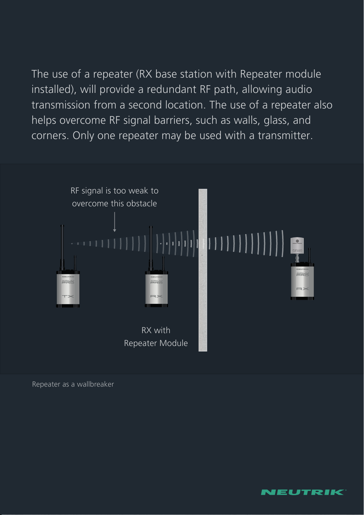
Repeater as a wallbreaker
Overcoming obstacles
The use of a repeater (RX base station with Repeater module
installed), will provide a redundant RF path, allowing audio
transmission from a second location. The use of a repeater also
helps overcome RF signal barriers, such as walls, glass, and
corners. Only one repeater may be used with a transmitter.
RX with
Repeater Module
RF signal is too weak to
overcome this obstacle
Multiple Transmitters
When using more than one transmitter, review the following
design considerations:
• Prevent one TX from overpowering another TX. This can be
done by using a different height for each transmission path.
If overpowering occurs, it could interrupt the audio signal
of the transmission.
• Keep a distance of at least 30 cm between each transmitter.
• When multiple transmitters are used the recommended
distance between TX and RX increases from 10 m to 30 m.
This distance compensates for higher overall RF power
levels when multiple transmitters are used in close proximity
to one another.
• Maintain one unoccupied RF channel between transmitters.
The XIRIUM PRO app performs this function automatically.
If the transmitter channel is selected manually the user must
make sure to assign non-adjacent channels.
• Generally we recommend using the RX RF attenuator, if the
RSSI-level allows it.

Enjoy using the XIRIUM PRO system!
min. 0,3 m
min. 30 m
Other manuals for xirium pro
4
Table of contents
Other NEUTRIK Stereo System manuals


