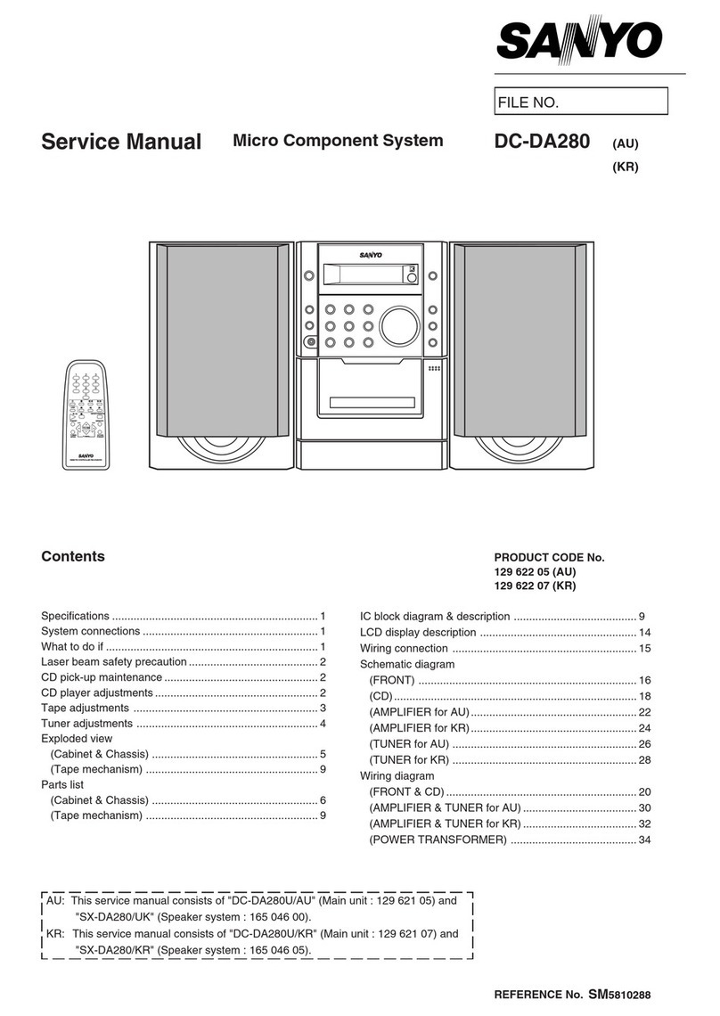
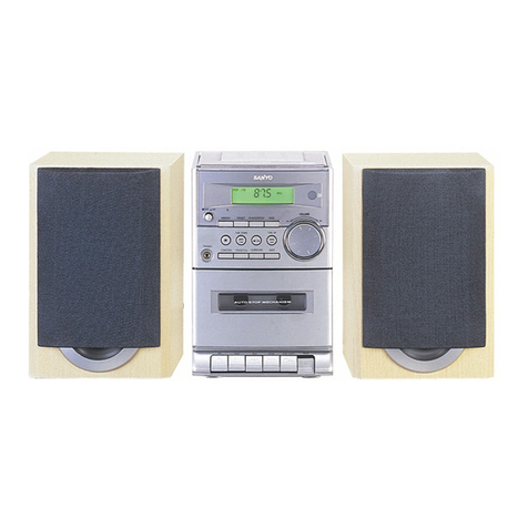
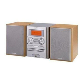
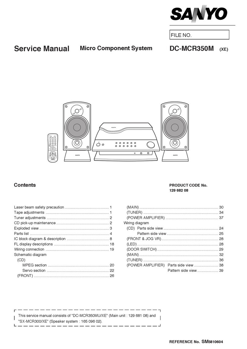
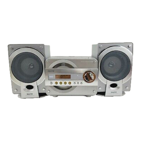
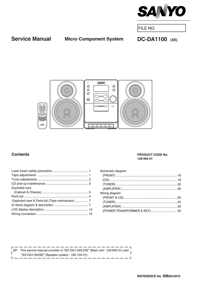
Sanyo DC-F210 User manual

IFILENo.
Service Manual
\
Contents
Mini Component System DC”F21 () (AU)
Specifications ................................................................... 1
Laser beam safety precaution .......................................... 1
What to do if .....................................................................2
Before use or transportation ............................................2
Removal &Installation .....................................................3
CD changer operation &Description ...............................4
CD changer replacement .................................................6
CD mechanism adjustments ............................................9
CD pick up maintenance .................................................. 11
CD player adjustments ..................................................... 11
Tape deck adjustments .................................................... 13
Tuner adjustments ........................................................... 15
Exploded view
(Cabinet &Chassis) ...................................................... 16
(CD changer mechanism 1/2 )......................................24
(CD changer mechanism 2/2 )......................................26
(CD base mechanism) ..................................................27
(Tape mechanism) ........................................................28
Parts list
(Cabinet &Chassis) ...................................................... 18
(CD changer mechanism) .............................................25
(CD base mechanism) ..................................................27
(Tape mechanism) ........................................................29
—
11111 [1 II IIII I
~his service manual consists of “DC-F21 OU” (Main unit), 1
——— ——— ——— —. ——— ——— —
.- l“RB-F21 O’ (Remote control) and“SX-F210“ (Speaker system). J
——— ———
PRODUCT CODE No.
12952604
Wiring connection ............................................................3O
Schematic diagram
(CD) ...............................................................................32
(FRONT) .......................................................................36
(TUNER) .......................................................................40
(AMPLIFIER) .................................................................44
(DECK) ..........................................................................48
Wiring diagram
(CD) ...............................................................................34
(FRONT) .......................................................................38
(TUNER) .......................................................................42
(AMPLIFIER) .................................................................56
(DEcK) ..........................................................................49
(OTHER) .......................................................................50
IC &Transistor voltages ...................................................5l
FL display description ......................................................53
IC block diagram &description ........................................54
REFERENCE No. SM580861

SPECIFICATIONS
Tuner section
Reception frequency
FM ........................................ 87.5 MHz -108 MHz
AM ....................................... 522 kHz -1710 kHz
CD changer section
Type ....................................... Changer, 3-disc
Channels ................................ 2-channel stereo
Sampling frequency ...............44.l kHz
Pick-up . ......... .................. .. . Optical 3-beam
semiconductor laser
Frequency response ..............20 Hz -20 kHz
Wow and Flutter ..................... Below measurable limits
Cassette deck section
Track system .........................4-track. 2-channel stereo
Frequency response ..............80 Hz -13.5 kHz (Normal tape)
Signal to noise ratio ...............45 dB
Wow and Flutter ..................... 0.15% (WRMS)
Tape speed ............................ 4.75 cmlsec.
Fast forward /Rewind time . . Approx. 110 sec. (C-60)
Amplifier section
Output power ....................... 22.5 Wx 2
(at 4ohms, 10% distortion)
Sound preset ....................... 4electronic presets
Inputs ................................... VIDEO IN :400 mV /50k ohms
Outputs ......................... ... . SPEAKERS :4 ohms
PHONES :8-32 ohms
LASER BEAM SAFETY PRECAUTION
CAUTION :
USE OF CONTROLS OR ADJUSTMENTS OR
PERFORMANCE OF PROCEDURES OTHER
THAN THOSE SPECIFIED HEREIN MAY RESULT
IN HAZARDOUS RADIATION EXPOSURE.
LASER OUTPUT ..................0.6 mW Max. (CW)
WAVE LENGTH .................... 790 nm
General
Power requirements ............... AC 230-240 V, 50 Hz
Power consumption ...............74 W
Dimensions (W xHxD) ........ Approx. 270x 300x 313 mm
Weight .................................... Approx. 6.9 kg
RB-F21 OWireless remote control
Power requirements ...............2 “AA’ batteries
Dimensions (W xHxD) ........ Approx. 56x 180x 18
Weight .................................... Approx. 58 g
(without batteries)
SX-F21 OSpeaker system
Type ....................................... 3way bass reflex
Drivers ................................... Woofer: 12 cm cone type
Tweeter: piezoelectric
Super tweeter: piezoelectric
Maximum
Power-handling capacity .....45 W(peak)
Nominal impedance ...............4 ohms
Dimensions (W xHxD) ........ Approx. 200x 300x 235 mm
Weight .................................... Approx. 2.2 kg (per speaker)
Specifications subject to change without notice.
CAUTION-INVISIBLELASERRADIATIONWHENOPENAND
INTERLOCKSDEFEATED.AVOIDEXPOSURETOBEAM.
ADVARSEL-USYNLIGLASERSTRALINGVEDABNING,NAR
SIKKERHEDSAFBRYDEREERUDEAFFUNKTION,UNDGAUDSA31ELSE
~A
VARNING-OSYNLIGLASERSTRLNINGNARDENNADELAROPPNAD
OCHSPARRARURKOPPLAD.STRALENARFARLIG.
VORSICHT-UNSICHTBARELASERSTRAHLUNGTRlll AUS,WENN
DECKELGEOFFNETUNDWENNSICHERHEITSVERRIEGELUNG
UBERBRUOCFIST.NICHT,DEMSTRAHLAUSSETZEN.
VARO-AVATTAESSAJASU(IJALUKITUSOHITETTAESSAOLETALTTIINA
NAKYMATTOMALLELASERSATEILYLLE.ALAKATS4)SATEESEEN. /
I1
/
\1
+- 3
.. . . . . . . . . . .
g
)
EEEiiEa-~m-~
%“’sMHllllllloll
Wlllllull
Nmlllll m
-1-
-- ●If the operation of the unit or display is not normal,or you wish to
clear the contents of the memory.
1.
2.
3.
4.
Disconnect the power cord’s plug from the electrical outlet.
Press the RESET button for at least 30 seconds.
Connect the power cord.
Press the POWER button to turn the power on.
$RESET
—- b
BEFORE USE OR TRANSPORTATION
●Before use
1. Remove the shipping screws from the rear of the unit.
2. This screw is used to secure the CD mechanism during
shipment and should be retained for future use.
cBefore transportation
1. Turn on the power and remove all discs from the unit.
2. Turn the POWER off. [STANDBYl lights.
3. Then unplug the power cord from the AC outlet.
4. Reinstall the shipping screw.
-2-

REMOVAL AND INSTALLATION
●Press the “POWER” button and check that the STANDBY LED Iiahts.
●Disconnect the power cord’s plug from the electrical outlet.
oAll wiring should be returned to the original position after work is completed.
●First have ready may the new FIXERS(614 129 4971) for replacement..
●Arrange the lead wires so that they are not near the heat sink.
1. CABINET ASSY
\
3. TAPE AND CD MECHANISM BLOCK
2. FRONT PANEL BLOCK
~CHASSIS @
\k
,+PULL
FRONT PANEL
4. POWER TRANSFORMER
-3-

CD CHANGER OPERATION AND DESCRIPTION
●This set is capable of stocking and playing up to 3CDs.
.
●While playing aCD, other discs can be replaced.
In this case, press the button for the disc No. you wish to remove, and then press the OPEN/CLOSE button.
●When the “POWER” button is turned off, the power turns off after the discs are loaded in the discs trays.
1. MOTOR &MECHANISM SWITCHES LAYOUT ~LOAD/UNLOAD MOTOR
UNLOAD SWITCH(SW5) 1IA-K%-RRLW4)
.
OPEN/CL
MOTOR b:.l]
==-.
&\L)2z&’- \/LsL~~)’Jo~oR
DISC 1‘/“”
SPINDLE MOTOR
DISC 2
DISC 3UP/DOWN MOTOR
2. FUNCTION
(1) OPEN/CLOSE
1. The rotation of the OPEN/CLOSE MOTOR rotates the
OPEN/CLOSE IDLER GEAR via the BELT and PULLEY,
and the RACK GEAR which is intermeshed with the
OPEN/CLOSE IDLER GEAR moves forward during
“OPEN”, backwards during “CLOSE”.
.
2.
.-
3.
The HOME POSITION is reached when the largest
square hole in the UP/DOWN CAM GEAR is between
the SENSORS.
Rotate the UP/DOWN CAM GEAR counter-clockwise
(with OPEN/CLOSE during PLAY) or clockwise (with
normal OPEN/CLOSE), raise the GEAR-BLOCK
BRACKET, stop at the selected TRAY, hold the TRAY
GUIDE by means of the OPEN/CLOSE RACK and save
the other TRAY GUIDES.
The OPEN/CLOSE motor start running, the OPEN/
CLOSE RACK moves forward, the TRAY LOCK LEVER
is raised to lock the TRAY, and the OPEN operation
commences.
CLOSE END SWITCH
OPEN/CLOSE RACK GEAR
?& =I
I—/ /—/— L@----
-/I / I I
GEAR BLOC’KBRACKET /BELT u
OPEN END SWITCH
SENSOR P.W B
GEAR BLOCK BRACKET A‘R,YSLIDE
-4-

CD CHANGER OPERATION AND DESCRIPTION
4. When the TRAY closes and it reaches the tip of RIB part of LEFT TRAY GUIDE, the LOCK LEVER is lowered to release the
TRAY, and loading proceeds.
TRAY GuIDE HOLDER
LOCK \EVER OPEN ~CLOSE
TRAY ~OCK RiB /
TRAY RELEASE
(2) LOADING
1. The rotation of the LOAD/UNLOAD MOTOR rotates the LOAD/UNLOAD DRIVE GEAR in the clockwise direction.
2. The DRIVE GEAR and the gear portion of the TRAY mesh together and the TRAY movers backward.
3. The completion of TRAY movement causes the UP/DOWN MOTOR to operate and lower the TRAY HOLDER putting the until
to chucking status.
4. The rotation of the UP/DOWN MOTOR rotates the UP/
DOWN GEAR in the counter-clockwise direction. In
connection with this, the TRAY HOLDER SLIDE moves
forward, and at the same time, the RIGHT SLIDE is moved
backwards by the SYNCHRO LEVER.
LEFT
~1-\LOAD/UNLOAD CAM GEAR
KrLOAD/UNLOADMOTOR
L-LoAD/UNLOAD DRIVE GEAR
TRAY
SYNCRO LEVER
UP/DOWN CAM GEAR 1
//
UP/OOWN IDLER 2
UPIDOWN DRIVE GEA~l UPIDOWN IDLER 1
RIGHT SLIDE BRACKET ‘
UP/DOWNDRIVEGEAR2“\ ‘UPIDOWN IOLER2
UPIDOWNCAMGEAR2
-5-

CD CHANGER REPLACEMENT
1. LOAD/UNLOAD FUNCTION
1. Remove the BTOP ENCOURAGE.
2. Remove the CD MECHANISM.
2. HOW TO REMOVE THE TRAYS
1.Remove the CHUCK BRACKET.(O -@)
TRAY HOLOER
“+’’’’OOwNOwN m. GEAR
L
2. Rotate the UP/DOWN CAM GEAR and position the collar
part of the TRAY HOLDER visible from the RIGHT SLIDE
at the midpoint between the CHUCKING and TRAY.
RIGHT SIDE
DISC STOPPER BRA~KET
ITRAi’ ?, CHUtKING
RAGE
3. Remove the three TRAYS through the gap at the back.
TRAY ASSY
3. REPLACING THE TRAY GUIDE
●Have the LEFT TRAY GUIDE HOLDER and TRAY GUIDE ready before proceeding.
1. Turn the UP/DOWN CAM GEAR and remove the setscrew of the TRAY HOLDER from the hole in the GEAR BLOCK BRACKET.
2. Turn the UP/DOWN CAM GEAR counter-clockwise as far as it will go, and remove the SCREWS.
R
3. Remove the five set screws of the LEFT TRAY GUIDE
HOLDER, and remove it in the direction of the arrow.
4. When assembling the parts, align the TRAY SLIDE and UP/
DOWN DRIVE GEAR.
IUPIDOWN
MARK DRIVEGEAR
~. --- -o@
TRAY SLIDE
HI 0
I
-6-

CD CHANGER REPLACEMENT
4. LEFT SLIDE BRACKET ——— ——. ——— ——— ———
t_&
*d
/‘\ IEM.50L ............................... MoLYKoTE. EM.5oL
IsG.7 ...................................sANGREAsE. sG.7
2a=% G474 B............................... FLOIL OIL, G-474B
SG-7
~.
——— ——— ——— ——— ——— —
1\//w#/\ “
5. UP/DOWN CAM GEAR
7. SETTING UP THE LOAD/UNLOAD GEAR
?-.’S7-7
I I
8. TRAY HOLDER
–1 I
I
–-l
dxLOADIUNLOADCAMGEAR
‘LOAD/UNLOAD DRIVE GEAR
-7-

CD CHANGER REPLACEMENT
.-. 9. sETTING uPTHETRAY sLIDEAND uP/DowNDRlvEGEAR2
1.Slide the TRAY SLIDE forward until itgoesnofur’fher.
2. Align the round mark on the UP/DOWN DRIVE GEAR 2.
with the mark area on the TRAY SLIDE, and install.
3. Align the shorter flat part of the UPIDOWN CAM GEAR 2,
and install.
.Set the parts in such away that the round marks on the two
GEARS are horizontal.
IJP/DOWN DRIVE GEAR 2
—
10. SEITING UP THE TRAY HOLDER AND UP/DOWN DRIVE GEAR
1.
2.
3.
4.
5.
6.
7.
Loosen and install the SET SCREW of the SENSOR P.W.B.
Slide the TRAY HOLDER SLIDE forward until it goes no
further.
Align the round mark on the UP/DOWN DRIVE GEAR 1with
the mark area on the TRAY HOLDER SLIDE, and install.
Secure the screw.
As shown in the figure, place the UP/DOWN DRIVE GEAR 2
and UP/DOWN CAM GEAR 2in such away that they are
horizontal.
Align with the triangular mark through the hole through which
the UP/DOWN CAM GEAR 2teeth are visible.
Secure the SCREW of the SENSOR and GEAR.
11. TRAY HOLDER SLIDE
UPIDOWN MOTOR ASSY— m
OWNCAMGEAR2
LONG
UP/DOWN CAM GEAR 2
●Set the parts in such away that the round marks on the two
GEARS are horizontal.
b’
10.5mm
7
(614287 0440)
-8-

CD MECHANISM ADJUSTMENTS
1. REPLACEMENT AND LUBRICATION OF THE CD MECHANISM
rNote:
——— ——— ——— —— 1
IEM-50L MOLYKOTE, EM-50L [
I‘G-7 SAN GREASE, SG-7 I
LG-474B FLOIL OIL, G-474B
——— ——— ——— —— -1
LUG
CONNEC
CD P.W.B
2. CD BASE MECHANISM
SLED
MOTOR
d
SPINDLE
MOTOR I
1+fl”
>
QOo)l
I? on
+PLU’S MARK +PLUS MARK
#
lT- [
PLAY LUG
SWITCH
,4;
UP/DOWN LUG
MOTOR o
SENSOR
P.WS3
i@9TuRNTA’LE
SPINDLEMOTOR~ ,%, 1~
SLED RETARD GEAR 1– @
S=TARDGEAR’* &
‘L_Lj---q eSPINDLE/SLED MOTOR P.W.B
a
u
-9-

CD MECHANISM ADJUSTMENTS
.. . 3. CD MECHANISM
(1) Replacement of the spindle motor “$::%-
.
.
1.
2.
3.
4.
5.
6.
7.
8.
First, prepare the new turntable and new special washer for
replacement. The removed turntable will be deformed by BOND ~
the heat of the soldering iron, and cannot be reused.
6
2mm
Prepare dial-type calipers. WASHER ‘ABOUT
The attached bonding material can be dissolved by using aTSmm
60 Wsoldering iron to heat the shaft the upper part of the
turntable for about one minute.
The turntable can then be removed from the shaft by very
carefully applying force upward at the center of the lower
surface of the turntable.
Remove the two screws and remove the spindle motor.
Attach the special washer top the spindle motor.
Clean the spindle motor’s shaft. To clean them, use asoft ?y
II II
ox
cloth soaked in isopropyl alcohol. 1’
‘m
—-TURNTABLE
Apply asmall amount of amixture of the “Three bond
2001” and “2015F’ bonding materials to the motor’s shaft. Igio
1.
2.
3.
4.
.—
5.
Install the turntable as shown in the figure.
Secure the turntable by pressing gently. Be sure to wipe
away (by using apiece of cloth, or similar material) any
bonding material coming out of the hole. <;G: ; ~~
H’a
SHAFT
I‘L$’
(2) Replacing the pick-up SPECIAL/
&
-. @~ “CKUP
Insert the pick-up rail into the base chassis. WASHER UC
If the rack of the base chassis are missing when the pick-up . .
u“. .
SPINDLE MOTOR /
rail have been installed, first wipe the tips of the rail with *
alcohol.
@
.
After the pick-up has been replaced, apply grease (FLOIL SLED MOTOR “o“‘o &&
.
“1
G-474B) to the _sections.
\iA
%
The pick-up P. W. Board pattern is “shorted”, as shown in c1
the figure, so that the new pick-up will not be susceptible to PICKUP RACK GEAR
the effects of static.
Set the pattern to “open” after the pick-up has been
replaced. (BE SURE AT THIS TIME, NOT TO TOUCH ANY OTHER PART.)
fiiL~+mz
@- qz-----
(SHORT) (OPEN)
-1o-

CD PICKUP MAINTENANCE
About pick-up (Optical lens) Cleaning
Clean the lens with the specified cleaning disc or moisten acotton swab with isopropyl alcohol and cleaning paper.
Specified cleaning disc: LC-1 (Part code: 645 026 1961 ..... manufactured by SANYO.)
Regarding procedure of cleaning with moisten cotton swab, please refer to the attached as follows.
1. Cotton swab wrapped with Cleaning paper
2. Add the isopropyl alcohol
3. Gently move the tip of cotton swab just like adraw awhirlpool from inside to outside on the surface of lens.
CD PLAYER ADJUSTMENTS
1. PREPARATION
Measuring instruments, tools and filter
1. Test disc. :YEDS 18 (SONY) or etc.
2. Oscilloscope :SS5711 (1 OMHZ or dual-phenomenon) or
Memoryscope :DSS6521 (Storagescope)
3. Screwdrivers (non-metallic) for adjustments
2. INITIALIZATION OF RVIO1
II
vd
VR101 Initialization position
3. PARTS LOCATION
EYE PATTERN
“(-) VR101
TRACKING
Oscilloscope [
.......... BALANCE
(+) [
—(-) j
Oscilloscope
TRACKING
BALANCE CN101
TEST POINT TP4(VC)
-11-

CD PLAYER ADJUSTMENTS
._ 4. ADJUSTMENTS
Adjustment Measuring
Item instrument
(a) Tracking Oscilloscope
balance
(b) Checking the’’eye” Oscilloscope
pattern
L
(1) Tracking balance adjustment
Service output Adjustment
mode connection location
yes TP3 :TE VRIO1
TR4 :Vc
TP1 :RF
TP4 :VC
1.
2.
3.
4.
5.
6.
7.
Connect an Oscilloscope to TP3 (TE) and TP4 (VC).
Turn “POWER” switch on.
Set the test disc. (DISC 1)
Press “SOUND PRESET” key and “FM MODE” key
simultaneously .Within 1second after pressing the
“MEMORY” switch.
(SERVICE MODE :Tracking balance adjustment mode)
Confirm that the oscilloscope waveform is symmetrical on
the top and bottom in relation to OV (VC).
If it cannot be adjusted by fully rotating VR1OI, cut the
resistor RI 108 (10kf2) with apair of pliers, and adjust
again.
To cancel service mode, disconnect the power cord’s plug
from the electrical outlet.
Adjustment value
Waveform symmetry
A=B
Check be sure that the “eye”
pattern is at the center of the
waveform and that the diamond
shape is clearly defined.
a
ICH1. Ywmv CH2. 5WnlV. ,W*
DC1O 1CC1O 1I
t:: t::
,.: A,B
TE
3
Ov(vc) A
B
II
200mV/div.
5ms/div.
(2) Checking the “eye” pattern
1. Switch “ON” the POWER. TP1 +
(RF)O
2. Connect an oscilloscope to TP1 (RF) and TP4 (VC). OSCILLOSCOPE
3. Load the test disc. TP4
4. PLAY switch push ON. (Vc)”
5. Check to be sure that the “eye” pattern is at the center of II
waveform and that the diamond shape is clearly defined.
6. Press the STOP button.
7. Switch “OFF” the POWER.
DED
b
-12-

TAPE ADJUSTMENTS
Adjustment Item
(a) HEAD AZIMUTH
DECK “A”
(b) HEAD AZIMUTH
DECK “B”
(c) MOTOR SPEED
(NORMAL)
Test Tape
VT1738 etc.
(1OKHZ)
Vl1738 etc.
(1OKHZ)
MlT-l 11
(3,000Hz)
Measuring
Instrument
AC-voltmeter
AC-voltmeter
FREQUENCY
COUNTER
Output connection Adjust IAdjust
location value I
SPEAKER TERMINAL HEAD AZIMUTH Max.
SCREW
SPEAKER TERMINAL HEAD AZIMUTH Max.
SCREW I
SPEAKER TERMINAL VR301 3,00QHz
1. HEAD REPLACEMENT AND AZIMUTH ADJUSTMENT
(1) Head replacement
1. After replacement, demagnetize the heads by using a
degausser.
2. Be sure to clean the heads before attempting to make any
adjustments.
3. Be sure both channels (1 and 2) are the same level.
(Using adual-channels oscilloscope).
4. All wiring should be returned to the original position after
work is completed.
(2) Head azimuth
.
1.
2.
3.
4.
5.
.
1.
2.
3.
4.
5.
DECK “A”
Remove the left side of CASSETTE LID.
Load atest tape (VTT-738, etc. :1 OKHZ) for azimuth
adjustment.
Press the PLAY button.
Use aflat-tip (-) screwdriver to turn the screw for normal
azimuth adjustment so that the left and right outputs are
maximized at the same phase during normal playback.
Press the STOP button
DECK “B”
Remove the right side of CASSETTE LID.
Load atest for azimuth adjustment.
Press the PLAY button
Azimuth screw adjustment.
Press the STOP button.
.After making the adjustment, secure the azimuth
DECK “B” DECK “A”
E.HEAD RIP HEAD PLAY HEAD
33%
BROWN YELLOW ,, RED
=
YELLOW– RED
WHITE WHITE
ORANGE
/
adjustment screw by applying screw lock (TB-1 401 B).
-13-

TAPE ADJUSTMENTS
2. MOTOR REPLACEMENT AND SPEED ADJUSTMENT
(1) Motor replacement
1. Seeillustration at right.
(2) Motor speed
1. Insert the test tape (MIT-111 or etc. 3,000 Hz) into DECK’A’ MOTOR SPEED ADJ.
2. Press the PLAY button.
3. Adjust VR301 so that the frequency counter show areading )Q
VR301
of 3,000 Hz.
4. Press the STOP button.
3. CHECKING THE MECHANISM TORQUES
●Clean the head, capstan and pinch roller before making any
measurement.
DECK “A&B“
Maasureent Tak&up torque Back tension Tape tension
Cassette for PLAY :TW-2111A PIAY:TW-2111A Drive-power cassette
measurement F.FWDIREW :TW-2231 TW-2412
PIAY 30- 60gr.cm 2.0- 5.Ogr.cm 60 gr or more
F.FWDIREW 55- 120gr.cm
-14-

TUNER ADJUSTMENTS
PARTS LOCATION
AN;EflNA
750hm
AM LOOP
ANTENNA a
L+
J2;Ol\Tp12(E)
@,TP1l(H)
L2101
I
t]J2013
T
~o ‘p26~R~2~Tp27(E)
tL2151-A Tp25fi==25
J
a
SG RF Level :75f2 open Voltage dBpV
Antenna :75Qunbalanced, Modulation:l kHz
1. FM Dev. :*22.5 kHz(MONO) *22.5 KHz(STEREO) +6.75 KHz(PILOT)
Step Adjusting Connection SC set Adjustment
Circuit Remark
Input output Frequency Position
1Cover --- Connect Digital DC voltmeter to 87.5 MHZ Low --- more than 0.8 V
voitage TP1 l(H), TP12(E).
--- 108.0 MHZ High --- lessthan 8.0 V
2Tracking Connect FM SG to Connect to VTVM 90.0 MHZ Low L2101 Max.
FM Antenna TP25(L) or TP26(R), TP27(E) 106.0 MHZ Hiah
SG Modulation :1 kHz, 30% Antenna, IRE Loop, Distance :60 cm
-.. ....
Step Adjusting Connection SG set Adjustment Remark
Circuit input output Frequency Position
1Cover --- Connect Digital DC voltmeter to 522 kHZ Low --- more than 1.0 V
voltage TP1 l(H), TP12(E).
--- 1710 kHZ l+igh --- kS than 8.0 V
2Tracking Connect AM SG to Connect to VTVM 603 KHZ Low L2151-A Max.
Test loopAnt. TP25(L) or TP26(R), TP27(E). 1404 kHZ High
-15-

..>>
“)

PARTS LIST
,- PRODUCT SAFETY NOTICE
EACH PRECAUTION IN THIS MANUAL SHOULD BE FOLLOWED DURING SERVICING. COMPONENTS IDENTIFIED WITH THE IEC
SYMBOL AIN THE PARTS LIST AND THE SCHEMATIC DIAGRAM DESIGNATED COMPONENTS IN WHICH SAFETY CAN BE OF
SPECIAL SIGNIFICANCE. WHEN REPLACING ACOMPONENT IDENTIFIED BY A,USE ONLY THE REPLACEMENT PARTS DESIGNATED,
OR PARTS WITH THE SAME RATINGS OF RESISTANCE, WATTAGE OR VOLTAGE THAT ARE DESIGNATED IN THE PARTS LIST
IN THIS MANUAL. LEAKAGE-CURRENT OR RESISTANCE MEASUREMENTS MUST BE MADE TO DETERMINE THAT EXPOSED
PARTS ARE ACCEPTABLY INSULATED FROM THE SUPPLY CIRCUIT BEFORE RETURNING THE PRODUCT TO THE CUSTOMER.
CAUTION :Regular type resistors and capacitors are not listed. To know those values, refer to the schematic diagram.
Regular type resistors are less than 1/4 Wcarbon type and Oohm chip resistors.
Regular type capacitors are less than 50 Vand less than 1000 LF type of Ceramic type and Electrical type.
L
PACKING &ACCESSORIES
REF. NO. PART NO.
6142914724
6142896242
6142896235
6450243745
6142316832
6142811078
4120555204
6142936221
6142914212
6142936207
6142914205
6450051227
6142450055
6450251481
6142853993
6142930809
CABINET &CHASSIS
REF. NO. PART NO.
1 6142895603
2 6142895610
3 6142913895
46142913901
5 6142895832
66142895849
7 6142896198
8 6142708316
9 6142940730
10 6142913857
11 6142914045
12 6142896129
13 6142913840
14
15
16
17
18
19
20
21
22
23
24
6142913864
6142895597
6142913918
6142928448
6142895573
6142895580
6142899212
6142913819
6142895634
6142936801
6142913796
25 6142708408
26 6142895627
27 6142896105
28 6142898437
—29 6142942642
DESCRIPTION
CARTON CASE
CUSHION, TOP
CUSHION, BOTTOM
POLY SHEET-1300X550, SET
LABEL, SAFETY
LABEL, CAUTION, SET TOP
SPECIAL SCREW-3.0X18.5,
SHIPPING SCREW
FIXER
LABEL, CAUTION, SHIPPING SCREW
INSTRUCTION MANUAL
ASSY,ANTENA,LOOP
ANTENNA
REMOCON,RB-F21OXE
BATTERY COVER, REMOTE CONTROL
AssY,Box,sPEAKER, sx-F210/uK
DESCRIPTION
DEC,WINDOW,CASSETTE, LEFT
DEC,WINDOW,CASSETTE, RIGHT
COVER, CASSETTE,LEFT
COVER, CASSETTE, RIGHT
LID,CASSETTE,LEFT
LID, CASSETTE, RIGHT
SPRING, WIRE, LID,CASSETTE
ASSY,GEAR
ASSY,CABINET,FRONT
BUITON,VOLUME,VOLUME
PANEL, OPERATION
DEC,SHEET,BUTTON, SOUND
BUITON,SOUND,
SOUND PRESETBASS XPANDER
BUTTON, SOUND,SRS
DEC,WINDOW,FL
DEC,ESCUTCHEON, CHANGER
SPRING TENS, DOOR,CD
DOOR,CD
DEC,WINDOW,DOOR
ASSY,CABINET
BUTTON, TUNING, CLOCWTIMER
DEC,WINDOW,STANDBY
BUTTON, POWER, POWER FUNCTION
BUTTON, CD, OPERATION,
CD OPERATION
HOLDER,DECK PWB
DEC,WINDOW,CD,DOOR,
ILLUMINATION
DEC,SHEET,DOOR, LIGHT
DEC,WINDOW,LED, SOUND PRESET
ASSY,BUTTON,CHANGER
REF. NO.
30
31
32
33
34
35
36
37
38
39
40
41
46
or
47
48
53
54
55
56
57
59
60
61
62
68
69
70
71
72
77
PART NO.
6142913925
6142913932
6142913949
6142913956
6142913963
6142913970
6142913987
6142913994
6142914007
6142914014
6142895719
6142913833
6141291710
6142841877
6141300382
6142913758
6142895894
6142896112
6142895887
6142895702
6142898482
6142895870
6142708484
6142914618
6142898475
6142921364
6142661918
6141256443
6141299136
6142896181
6142918050
6141913698
6142762844
6142080986
FIXING PARTS
REF. NO. PART NO.
Y1 4110213701
Y2 4110213701
Y3 4110213701
Y4 4110213701
Y5 4110213701
Y6 4110013905
Y8 4110213503
Y9 4110213503
Ylo 4110213503
Y11 4110213503
DESCRIPTION
KNOB, LEVER, B-MECHA, REC
KNOB, LEVER, B-MECHA,PLAY
KNOB, LEVER, B-MECHA,REW
KNOB, LEVER, B-MECHA,FWD
KNOB, LEVER, B-MECHA,STOP
KNOB, LEVER, B-MECHA,PAUSE
KNOB, LEVER,A-MECHA,PLAY
KNOB, LEVER,A-MECHA,REW
KNOB, LEVER, A-MECHA,FWD
KNOB, LEVER, A-MECHA,STOP
HINGE, BUTTON, VOLUME
BUTTON, TUNER,
PRISET/TUNING/BAND/ETC.
FIXER,AC CODE
FIXER,AC CORD
LUG, BOITOM-LEAD
ASSY,CABINET,BOTTOM
REFLECTOR, BUTTON, CAHNGER
DEC,SHEET,BUTTON, CHANGER
REFLECTOR, BUTTON, SOUND
HINGE, BUTTON, SOUND
REFLECTOR, LED, SOUND, PRESET
REFLECTOR, DOOR, LIGHT
SPRING, PLATE,REC
PANEL, REAR,HDG
PANEL, REAR,CD MECHA
TERMINAL,CD
JOINT, CHANGER MECHA
FORCEMENT
CUSHION, FRONT LEAD FIX
LUG, MECHA LEAD FIX
SHAFT, KNOB, LEVER, CASSETTE
COVER PICK,CD PICK COVER
LABEL, LASER MARK
LABEL, SAFETY, LASER CAUTION
CUSHION, MECHA LEAD FIX
DESCRIPTION
SCR S-TPG BIN 3X1 O,CABINET
SCR S-TPG BIN 3X1 O,BOTTOM-REAR
SCR S-TPG BIN 3X1 O,VIDEO IN
SCR S-TPG BIN 3X1O,
REAR-REAR/EXT.ANT
SCR S-TPG BIN 3X1O,
MECHA CD-REAR
SCR S-TPG BIN 4X6, TRANS
SCR S-TPG BIN 3X1O,
DECK-PWB/MECHA
SCR S-TPG BIN 3X1O,
MECHA,CASSETTE
SCR S-TPG BIN 3X1 O,FRONT PWB
SCR S-TPG BIN 3X1 O,BUTTON, TUNER
-18-

PARTS LIST
REF. NO.
Y12
Y13
Y14
Y15
Y16
Y17
Y18
Y19
Y20
Y21
Y22
Y23
Y24
Y25
Y27
Y28
Y29
Y30
Y31
Y32
Y33
Y34
Y35
Y36
PART NO.
4110213503
4110213503
4110213503
4110213503
4110213503
4110213503
4110213503
411 1653803
411 1653803
411001 1901
4110243708
4120326408
4110282806
4110282905
4110209407
4110213503
4110215705
4110216405
4110209902
4110216405
4110209100
4110209902
4110243708
4110209902
ELECTRICAL PARTS
REF.NO. PART NO.
80 A4230169902
81 A6450246098
82 ~6142565285
or A6450178658
83 6142923931
84 6142657034
85 4050951602
or 4050951701
or 4051386403
86 6450251405
CN381 6142933275
CN382 6142933282
CN383 6142615249
CD P.W.BOARD ASSY
REF.NO. PART NO.
91 6142942666
CN101 6450060915
CN1ll 6450101472
CN113 6450058127
CN114 6450122736
DESCRIPTION
SCR S-TPG BIN 3X1O,
HINGE,BUTTON,SOUND
SCRS-TPGBIN3X1O,
HINGE,BUTTON,VOLUME
SCRS-TPGBIN3X1O,
BUTTON POWER
SCRS-TPG BIN3X1O,BOTTOM-FRONT
SCRS-TPGBIN3X1O,
TERMINAL,CD-CD MECHA
SCRS-TPGBIN3X1O,
HEATSINK-REAR
SCRS-TPGBIN3X1O,
MECHACD-FROUT
SCRS-TPGBIN2.3X1O,
PANEL,OPERATION
SCR S-TPG BIN 2.3X1O,
DEC,ESCUTCHEON, CHANGER
SCR S-TPG BIN 3X6, COVER PICK FIX
SCR S-TPG PAN+FLG 2X6,
HOLDER DECK PWB
SPECIAL SCREW, GEAR, CASSETTE
SCR S-TPG PAN 2X3,
SPRING PLATE FOR REC
SCR S-TPG PAN 2X4,
JOINT-CD MECHA
SCR S-TPG BRZ+FLG 3X14,
SHAFT, KNOB, LEVER
SCR S-TPG BIN 3X1 O,COVER PICK FIX
SCR S-TPG BIN 3X6, BOTTOM-LUG
SCR S-TPG BIN 3X8, HEAT-HEAT
SCR S-TPG BRZ+FLG 3X8,
PWB-HEAT SINK
SCR S-TPG BIN 3X8,M0 TRANSISTOR
SCR S-TPG BRZ+FLG 3X12, POWER IC
SCR S-TPG BRZ+FLG 3X8,
AMP PWB-BOTTOM
SCR S-TPG PAN+FLG 2X6
SCR S-TPG BRZ+FLG 3X8,
PWB-CD MECHA
DESCRIPTION
FUSE 250V 0.8A
TRANS,POWER,AC240V 50HZ
POWER CORD
POWER CORD
HEAT SINK, POWER AMP
TR 2SD2061-E,MAIN POWER+B
TR 2SD2061-F,MAIN POWER+B
TR KTD2058Y,MAIN POWER+B
FLEXIBLE FLAT CABLE, FRONT-CD
ASSY,WIRE,P HEAD
ASSY,WIRE,R/P HEAD
ASSY,WIRE,C-MECHA SW
DESCRIPTION
ASSY,PWB,CD
PLUG,4P,TP1-4
SOCKET,FPC 13P,CD PICKUP
PLUG,6P,BASE MECHA
SOCKET, DIP 8P,CD CONNECTOR
REF. NO.
CN115
CN124
CN125
CN131
or
CN198
D1350
or
or
or
D1351
D1361
D1371
D1601
D1602
D1603
D1604
Iclol
IC102
IC104
IC106
or
IC131
IC132
L1401
LG101
PR161
PR162
PR191
PR199
QIIO1
or
or
QI102
or
or
Q1201
or
or
Q1202
or
or
Q1211
or
or
Q1321
or
or
Q1351
or
or
Q1361
or
or
Q1371
or
or
R1350
R1371
VR101
X1401
or
PART NO.
6140354935
6142940754
6142940761
6450125201
6450054242
6450059292
4070079904
4070124406
4070125809
4071536109
4070995402
4070995105
4070994504
A4070049709
A4070049709
A4070049709
A4070049709
4093273402
A4093178509
4093867502
4090397408
4090184305
/5 4094081402
A4094081303
6450014550
6450238987
A6450142468
A6450142468
A6450142499
A6450142536
4050086809
4050087202
4050087301
4050086809
4050087202
4050087301
4050095207
4050019302
4051413604
4050086809
4050087202
4050087301
4050003806
4051289001
4050370809
4050207402
4050207204
4050122002
4050000508
4050782305
405001 1108
4050000508
4050782305
405001 1108
4050000508
4050782305
405001 1108
A4020721600
A4020721600
6450107597
6142546932
6142592137
DESCRIPTION
SOCKET, DIP 4P,CD CONNECTOR
ASSY,WIRE,CD-CDMECHA
SOCKET,FPC 16P,FRONT
SOCKET,16P,FRONT
PLUG,5P,AMP
DIODE GMAO1
DIODE 1SS133
DIODE 1SS176
DIODE 1SS119-041
ZENER DIODE MTZJ6.2B
ZENER DIODE MTZJ4.7B,LOADING-M
ZENER DIODE MTZJ3.9A,0PN/CLS-M
DIODE DSK1 OC
DIODE DSK1OC
DIODE DSK1OC
DIODE DSK1OC
ICCXA1782BQ
IC BA6398FP
IC CXD2508AQ
IC NJM4558D
IC LA6458D
IC LB1648L
IC LB1641L
INDUCTOR,1OU K
FIXER
PROTECTOR,0,63A 125V
PROTECTOR,0.4A 125V
PROTECTOR, I.5A 125V
TR 2SB808-F-SPA
TR 2SB81O-E
TR 2SB81O-F
TR 2SB808-F-SPA
TR 2SB81O-E
TR 2SB81O-F
TR 2SB927-S
TR 2SA1 020-Y
TR KTA1 273-Y
TR 2SB808-F-SPA
TR 2SB81O-E
TR 2SB81O-F
TR DTC114YS
TR RN1207
TR 2SC4048
TR 2SC945A-P
TR 2SC945A-K
TR 2SC1815-GR
TR DTA114ES
TR BN1A4M
TR RN2202
TR DTA114ES
TR BN1A4M
TR RN2202
TR DTA114ES
TR BN1A4M
TR RN2202
RESISTOR 10 J- lW
RESISTOR 10 J- lW
VR,SEMI,47K N
RESONATOR, CERAMIC
RESONATOR, CERAMIC
-19-

PARTS LIST
FRONT P.W. BOARD ASSY
.REF. NO.
92
BR601
C6003
or
CN601
CN602
CN603
or
CN604
CN612
D6001
D6004
D6005
D6011
D6012
D6013
D6014
D6015
D6016
D6017
=__
D6018
D6019
D6020
D6101
D6102
D6103
D6104
DS601
FL601
IC601
L6001
Q6001
or
or
or
or
or
Q6002
or
-— or
Q6003
or
or
or
or
or
Q6004
or
or
Q6011
or
or
Q6012
or
or
Q6014
or
or
Q6015
or
or
PART NO. DESCRIPTION
6142923498 ASSY,PWB, FRONT
6142895726 HOLDER,FL
4031964102 ELECT 1000U M6.3V
4033250401 ELECT IOOOUM 6.3V
6450090080 PLUG,16P,AMP/’TUNER
6140354928 SOCKET, DIP 3P,PT2
6450125201 SOCKET, FPC 16P,CD
6450054242 SOCKET,l 6P,CD
6142923207 CORD,l PCONNECTOR, AMP
6142889480 CORD,3P CONNECTOR, PT2
4070124406 DIODE 1SS133
4070994603 ZENER DIODE MTZJ3.9B
4080348700 LED SLZ-981C-13H-AB-T2,
STANDBY.LED
4080349202 LED SLZ-481 C-13H-AB-T2,SRS_LED
4080374204 LED SLP-31 18B-51 HAB-T1 ,DISC_LED
4080374204 LED SLP-3118B-51 HAB-T1 ,DISC_LED
4080348700 LED SLZ-981C-13H-AB-T2,
SOUND_ LED
4080348700 LED SLZ-981 C-13H-AB-T2,
SOUND_LED
4080348700 LED SLZ-981 C-13H-AB-T2,
SOUND.LED
4080348700 LED SLZ-981C-13H-AB-T2,
SOUND.LED
4070124406 DIODE 1SS133
4080356101 PHOTO DIODE PIC-21043TE3
6450235849 FLOURESCENT TUBE, FL
4102873302 IC M38174M8-290FP
6450014550 INDUCTOR,1OU K
4050061905 TR 2SA933S-S
4050061806 TR 2SA933S-R
4050021305 TR 2SA1 048-Y
4050021107 TR 2SA1048-GR
4050577604 TR 2SA1175-FF
4050025402 TR 2SA1175-EF
4050207402 TR 2SC945A-P
4050207204 TR 2SC945A-K
4050122002 TR 2SC1815-GR
4050061905 TR 2SA933S-S
4050061806 TR 2SA933S-R
4050021305 TR 2SA1 048-Y
4050021107 TR 2SA1048-GR
4050577604 TR 2SA1175-FF
4050025402 TR 2SA1 175-EF
4050207402 TR 2SC945A-P
4050207204 TR 2SC945A-K
4050122002 TR 2SC1815-GR
4050207402 TR 2SC945A-P
4050207204 TR 2SC945A-K
4050122002 TR 2SC1815-GR
4050003806 TR DTC1 14YS
4050370809 TR 2SC4048
4051289001 TR RN1207
4050003806 TR DTC1 14YS
4050370809 TR 2SC4048
4051289001 TR RN1207
4050003806 TR DTC114YS
4050370809 TR 2SC4048
4051289001 TR RN1207
REF. NO.
Q6016
or
or
S6006
or
S6007
or
S6008
or
S6009
or
S6010
or
S6011
or
S6013
or
S6014
or
S6015
or
S6016
or
S6017
or
S6018
or
S6019
or
S6020
or
S6021
or
S6022
or
S6023
or
S6024
or
S6025
or
TA601
X6001
or
or
X6002
PART NO.
4050003806
4050370809
4051289001
6142205433
6142400982
6142205433
6142400982
6142205433
6142400982
6142205433
6142400982
6142205433
6142400982
6142205433
6142400982
6142205433
6142400982
6142205433
6142400982
6142205433
6142400982
6142205433
6142400982
6142205433
6142400982
6142205433
6142400982
6142205433
6142400982
6142205433
6142400982
6142205433
6142400982
6142205433
6142400982
6142205433
6142400982
6142205433
6142400982
6142205433
6142400982
6141121444
6142155523
6142155561
6450137532
6142527627
DESCRIPTION
TR DTC114YS
TR 2SC4048
TR RN1207
SWITCH, TACT, DISC 1
SWITCH,TACT
SWITCH, TACT, DISC 2
SWITCH,TACT
SWITCH, TACT,DISC 3
SWITCH,TACT
SWITCH, TACT, OPEN/CLOSE
SWITCH,TACT
SWITCH, TACT, POWER
SWITCH,TACT
SWITCH, TACT, FUNCTION
SWITCH,TACT
SWITCH, TACT,BASS
SWITCH,TACT
SWITCH, TACT, SOUND
SWITCH,TACT
SWITCH, TACT,SRS
SWITCH,TACT
SWITCH, TACT, DUB/BEAT
SWITCH,TACT
SWITCH, TACT, PRESET+
SWITCH,TACT
SWITCH, TACT, PRESET-
SWITCH,TACT
SWITCH, TACT, MEMORY
SWITCH,TACT
SWITCH, TACT,TU BAND
SWITCH,TACT
SWITCH, TACT,FM MODE
SWITCH,TACT
SWITCH, TACT,VOL UP
SWITCH,TACT
SWITCH, TACT,VOL DOWN
SWITCH,TACT
SWITCH, TACT,TU+
SWITCH,TACT
SWITCH, TACT, TU-
SWITCH,TACT
DOUBLE FACE
RESONATOR, CERAMIC
RESONATOR, CERAMIC
OSC,CERAMIC 4.19 MHZ
RESONATOR,XTAL
SWITCH P.W.BOARD ASSY
REF. NO. PART NO. DESCRIPTION
93 6142900116 ASSY,PWB,SWITCH
LG621 6141299068 LUG
LP621 6140460094 LAMP
S6201 6142205433 SWITCH, TACT, FWD SKIP
or 6142400982 SWITCH,TACT
S6202 6142205433 SWITCH, TACT,BACK SKIP
or 6142400982 SWITCH,TACT
S6203 6142205433 SWITCH, TACT,PLAY PAUSE
or 6142400982 SWITCH,TACT
S6204 6142205433 SWITCH, TACT,STOP
or 6142400982 SWITCH,TACT
-20-
Table of contents
Other Sanyo Stereo System manuals

Sanyo
Sanyo DC-MCR60 User manual

Sanyo
Sanyo DC-PT70 User manual

Sanyo
Sanyo DC-D12 User manual

Sanyo
Sanyo RB-DA280 User manual

Sanyo
Sanyo DC-BM300 User manual

Sanyo
Sanyo DC-DA1000 User manual

Sanyo
Sanyo DC-DA280 User manual

Sanyo
Sanyo DC-T44 User manual

Sanyo
Sanyo DC-MCR50 User manual

Sanyo
Sanyo GXT 4615K User manual

Sanyo
Sanyo AWM-2600 User manual

Sanyo
Sanyo DC-DA1400M User manual

Sanyo
Sanyo DC -X1000MD User manual

Sanyo
Sanyo DMP-P690 User manual

Sanyo
Sanyo DC User manual

Sanyo
Sanyo DC-D5 User manual

Sanyo
Sanyo DC-F190 User manual

Sanyo
Sanyo DC-MM5000 (XE) User manual

Sanyo
Sanyo DC-DA1200V User manual

Sanyo
Sanyo DC-MCR30 User manual